Scanning Table for the Professional Maker

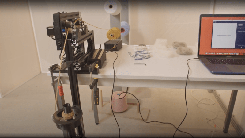
Sometimes the simplest objects need some overthinking. This is exactly what [Chris Borge] realized when using his 3D scanner and finding that the included rotation table left quite a bit to be desired — providing him the perfect excuse to build a new one.
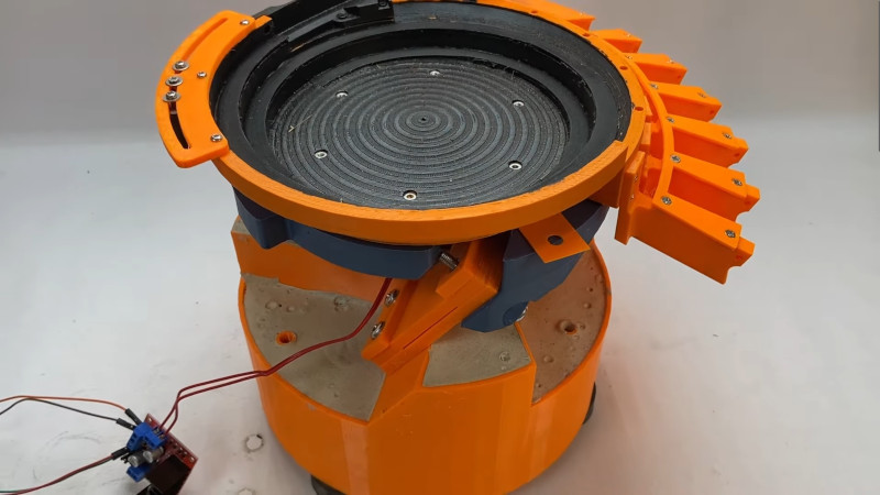
One of the main features of a rotation stage is the, well, rotation. This was done in [Chris]’s case with a NEMA 17 stepper motor, perfect for precise rotation of scanning. Hooking up the motor to a basic perf board with an Arduino Nano allows for on the fly adjustments to rotation speed. To really solidify the over-engineering, [Chris] applies his obligatory concrete mix to add some heft to the stage.
While the previous features could be removed/downgraded without much loss, the adjustable grid built into the top adds significant functionality. The grid is based on [Chris]’s past projects, which allows cross compatibility.
We love over-engineering here at Hackaday, especially when adding something new. For more prime overthought design, check out this over engineered egg cracker!