

Old CNC Brain Swapped With An Arduino
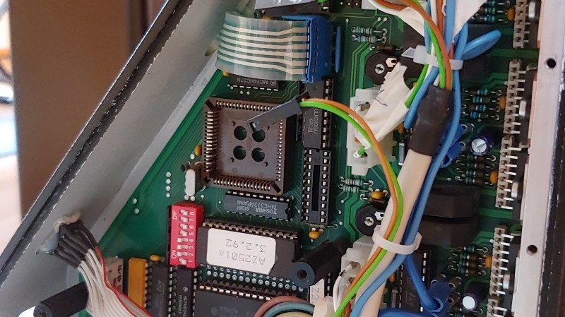
[Sebastian] and [Stefan Shütz] had a ISEL EP1090 CNC machine at home, sitting unused, and they decided to bring it to life. With pretty good mechanical specs, this CNC looked promising – alas, it was severely constrained by its controller. The built-in CPU’s software was severely outdated, had subpar algorithms for motor driving programmed in, and communication with the CNC was limited because the proprietary ISEL communications protocol that isn’t spoken by other devices.The two brothers removed the CPU from its PLCC socket, and went on to wiring a grbl-fueled Arduino into the controller box.
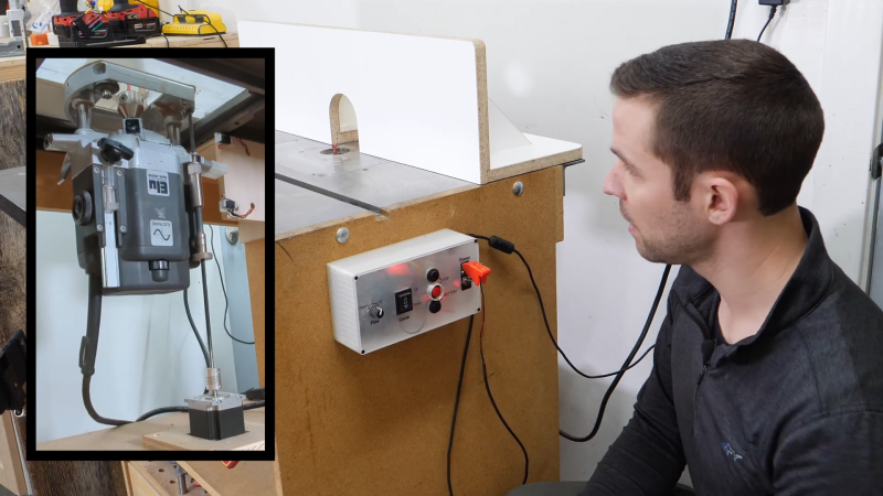
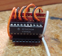 They reverse-engineered the motor driver connections – those go through a 74HC245 buffer between the original CPU and the drivers. Initially, they put an Arduino inside the control box of the CNC and it fit nicely, but it turned out the Arduino’s CPU would restart every time the spindle spun up – apparently, EMC would rear its head. So, they placed the Arduino out of the box, and used two CAT7 cables to wire up the motor and endstop signals to it.
For tapping into these signals, they took the 74HC245 out of its socket, and made an interposer from two small protoboards and some pin headers – letting them connect to the STEP and DIR lines without soldering wires into the original PCB. There’s extensive documentation, GRBL settings, and more pictures in their GitHub repo, too – in case you have a similar CNC and would like to learn about upgrading its controller board!
After this remake, the CNC starts up without hassles. Now, the brothers shall CNC on! Often, making an old CNC machine work is indeed that easy, and old controller retrofits have been a staple of ours. You can indeed use an Arduino, one of the various pre-made controller boards like Gerbil or TinyG, or even a Raspberry Pi – whatever helps you bridge the divide between you and a piece of desktop machinery you ought to start tinkering with.
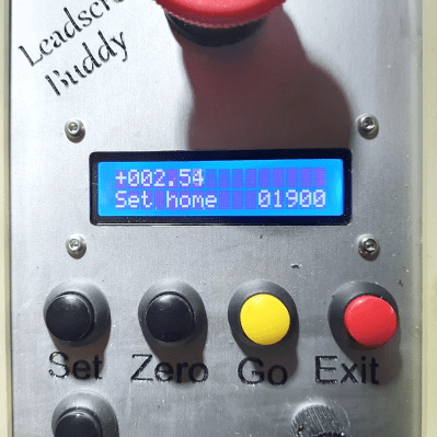 [Tony Goacher] took this idea a few steps further when he created the