Posts with «musical hacks» label

How To Build Jenny’s Budget Mixing Desk

Jenny did an Ask Hackaday article earlier this month, all about the quest for a cheap computer-based audio mixer. The first attempt didn’t go so well, with a problem that many of us are familiar with: Linux applications really doesn’t like using multiple audio devices at the same time. Jenny ran into this issue, and didn’t come across a way to merge the soundcards in a single application.

I’ve fought this problem for a while, probably 10 years now. My first collision with this was an attempt to record a piano with three mics, using a couple different USB pre-amps. And of course, just like Jenny, I was quickly frustrated by the problem that my recording software would only see one interface at a time. The easy solution is to buy an interface with more channels. The Tascam US-4x4HR is a great four channel input/output audio interface, and the Behringer U-PHORIA line goes all the way up to eight mic pre-amps, expandable to 16 with a second DAC that can send audio over ADAT. But those are semi-pro interfaces, with price tags to match.

But what about Jenny’s idea, of cobbling multiple super cheap interfaces together? Well yes, that’s possible too. I’ll show you how, but first, let’s talk about how we’re going to control this software mixer monster. Yes, you can just use a mouse or keyboard, but the challenge was to build a mixing desk, and to me, that means physical faders and mute buttons. Now, there are pre-built solutions, with the Behringer X-touch being a popular solution. But again, we’re way above the price-point Jenny set for this problem. So, let’s do what we do best here at Hackaday, and build our own.

The Physical Goods

What we need is a microcontroller that has native USB client support, multiple digital I/O pins, and some analog inputs. I went with the Arduino MKRZero for the small size, decent price, and the fact that it’s actually in stock at Mouser. The other items we’ll need are some faders and buttons. I went for the full-sized 100 mm faders, and some LED toggle buttons made by Adafruit. The incidentals, like wire and resistors, was sourced from the local parts bin in the corner.

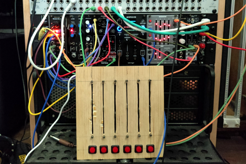
My first thought was to design and 3D print the panel, but after doing the layout on a scrap piece of plywood, the resulting size proved a bit too large for my printer. So we’re going retro, and making a “wood-grain” mixing desk. This would be a great project for a CNC router, but as I’m not part of that particular cool club yet, it was a drill press, table saw, and oscillating tool to the rescue. The results aren’t quite as pretty as I wanted, but maybe we’ll get a Mark II of this project one day.
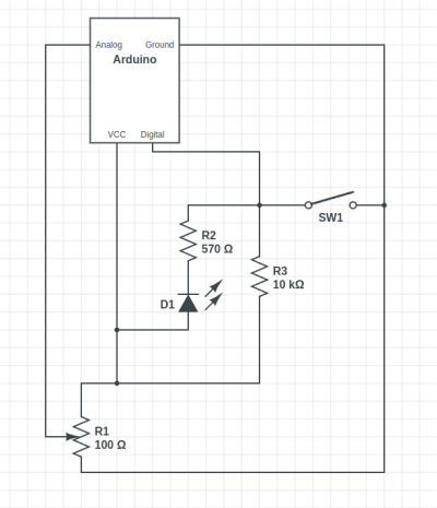
The wiring is relatively straightforward, with a current limiting resistor to protect the LEDs inside the buttons, and a pullup resistor to prevent the digital pin from floating when the button isn’t pushed. Now, that pullup might not be necessary, as I later learned that the Arduino has built-in pullup on its digital pins. And also of note, a 10 Ω resistor is *not* a good choice for a pullup. As Al eloquently put it, that’s a “pull way up resistor”. 10 kΩ is the better choice.

And to finish the build, we’ll need a sketch to run on the Arduino. Thankfully, there’s already a great library for exactly what we want to do: Control Surface. There’s a bunch of ways to set this up, but my sketch is pretty trivial:

#include <Control_Surface.h>
USBMIDI_Interface midi;

CCButtonLatching button1 {11, {MIDI_CC::General_Purpose_Controller_1, CHANNEL_1}, };
CCButtonLatching button2 {10, {MIDI_CC::General_Purpose_Controller_2, CHANNEL_1}, };
CCButtonLatching button3 {9, {MIDI_CC::General_Purpose_Controller_3, CHANNEL_1}, };
CCButtonLatching button4 {8, {MIDI_CC::General_Purpose_Controller_4, CHANNEL_1}, };
CCButtonLatching button5 {7, {MIDI_CC::General_Purpose_Controller_5, CHANNEL_1}, };
CCButtonLatching button6 {6, {MIDI_CC::General_Purpose_Controller_6, CHANNEL_1}, };
  
CCPotentiometer volumePotentiometers[] {
  {A0, {MIDI_CC::Sound_Controller_1, CHANNEL_1} },
  {A1, {MIDI_CC::Sound_Controller_2, CHANNEL_1} },
  {A2, {MIDI_CC::Sound_Controller_3, CHANNEL_1} },
  {A3, {MIDI_CC::Sound_Controller_4, CHANNEL_1} },
  {A4, {MIDI_CC::Sound_Controller_5, CHANNEL_1} },
  {A5, {MIDI_CC::Sound_Controller_6, CHANNEL_1} },
};
void setup() {
    Control_Surface.begin();
}
void loop() {
    Control_Surface.loop();
}

Pipewire to the Rescue

And now on to the meat and potatoes of this project. How do we convince an application to see inputs from multiple devices, and actually do some mixing? The problem here is de-sync. Each device runs on a different clock source, and so the bitstream from each may wander and go out of sync. That’s a serious enough problem that older sound solutions didn’t implement much in the way of card combining. Not long ago, the process of resampling those audio streams to get them to properly sync would have been a very CPU intensive procedure. But these days we all have multi-core behemoths, practical super-computers compared to 20 years ago.

So when Wim Taymans wrote Pipewire, he took a different approach. We have enough cycles to resample, so Pipewire will transparently do so when needed. Pipewire sees all your audio interfaces at once, and implements both the Jack and Pulseaudio APIs. Different distros handle this a bit differently, but generally you need the Pipewire packages, as well as the pipewire-jack and pipewire-pulseaudio packages to get that working.

And here’s the secret: The Jack routing tools work with Pipewire. The big three options are qjackctl, carla, and qpwgraph, though note that qpwgraph is actually Pipewire native. So even if an application can only select a single device at a time, if that app uses the Jack, Pulseaudio, or Pipewire API, you can use one of those routing control programs to arbitrary connect inputs and outputs.
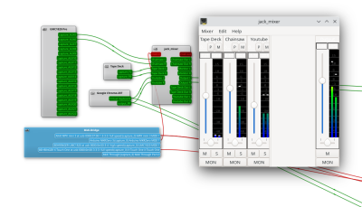
So let’s start with the simplest solution: jack_mixer. Launch the application, and then using your preferred routing controllers, take the MIDI output from our Arduino control surface, and connect it into jack_mixer‘s MIDI input. In jack_mixer, add a new input channel, and give it an appropriate name. Let’s call it “tape deck”, since I have a USB tape deck I’m testing this with. Now the controller magic kicks in: hit the “learn” button for the volume control, and wiggle the first fader on that controller. Then follow with the mute button, and save the new channel. We’ll want to add an output channel, too. Feel free to assign one of your faders to this one, too.

And finally, back to the routing program, and connect your tape deck’s output to jack_mixer input, and route jack_mixer‘s output to your speakers. Play a tape, and enjoy the full control you have over volume and muting! Want to add a Youtube video to the mix? Start the video playing, and just use the routing controller to disconnect it from your speakers, and feed it into a second channel on jack_mixer. Repeat with each of those five cheap and nasty sound cards. Profit!

You Want More?

There’s one more application to mention here. Instead of using jack_mixer, we can use Ardour to do the heavy lifting. To set it up this way, there are two primary Ardour settings, found under preferences: Under the monitoring tab make sure “Record monitoring handled by” is set to Ardour, and the “auto Input does talkback” option is checked. Then add your tracks, set the track input to the appropriate input hardware, and the track output to the master bus. Make sure the master bus is routed to where you want it, and you should be able to live mix with Ardour, too.

This gives you all sorts of goodies to play with, in the form of plugins. Want a compressor or EQ on a sound source? No problem. Want to autotune a source? X42 has a plugin that does that. And of course, Ardour brings recording, looping, and all sorts of other options to the party.

Ardour supports our custom mixing interface, too. Also under preferences, look for the Control Surfaces tab, and make sure General MIDI is checked. Then highlight that and click the “Show Protocol Settings” button. Incoming MIDI should be set to our Arduino device. You can then use the Ctrl + Middle Click shortcut on the channel faders and mute buttons, to put them in learn mode. Wiggle a control to assign it to that task. Or alternatively you can add a .map file to Ardour’s midi_maps directory. Mine looks like this:

 
  <?xml version="1.0" encoding="UTF-8"?>
<ArdourMIDIBindings version="1.1.0" name="Arduino Mapping">
  <Binding channel="1" ctl="16" uri="/route/mute B1"/>
  <Binding channel="1" ctl="70" uri="/route/gain B1"/>
  <Binding channel="1" ctl="17" uri="/route/mute B2"/>
  <Binding channel="1" ctl="71" uri="/route/gain B2"/>
  <Binding channel="1" ctl="18" uri="/route/mute B3"/>
  <Binding channel="1" ctl="72" uri="/route/gain B3"/>
  <Binding channel="1" ctl="19" uri="/route/mute B4"/>
  <Binding channel="1" ctl="73" uri="/route/gain B4"/>
  <Binding channel="1" ctl="80" uri="/route/mute B5"/>
  <Binding channel="1" ctl="74" uri="/route/gain B5"/>
  <Binding channel="1" ctl="81" uri="/route/mute B6"/>
  <Binding channel="1" ctl="75" uri="/route/gain B6"/>
</ArdourMIDIBindings>

The Caveats

Now before you get too excited, and go sink a bunch of money and/or time into a Linux audio setup, there are some things you should know. First is latency. It’s really challenging to get a Pipewire system set up to achieve really low latency, particularly when you’re using USB-based hardware. It’s possible, and work is ongoing on the topic. But so far the best I’ve managed to run stable is a 22 millisecond round-trip measurement — and that took a lot of fiddling with the Pipewire config files to avoid garbled audio. That’s just about usable for self monitoring and live music, and for playing anything pre-recorded, that’s perfectly fine.

The second thing to know is that this was awesome. It’s a bit concerning how much fun it is to combine some decent audio hardware with the amazing free tools that are available. Want to auto-tune your voice for your next Zoom meeting? Easy. Build a tiny MIDI keyboard into your desk? Just a microcontroller and some soldering away. The sky’s the limit. And the future is bright, too. Tools like Pipewire and Ardour are under very active development, and the realtime kernel patches are just about to make it over the finish line. Go nuts, create cool stuff, and then be sure to tell us about it!
Arduino Synthesizer Uses Modified Slide Pots

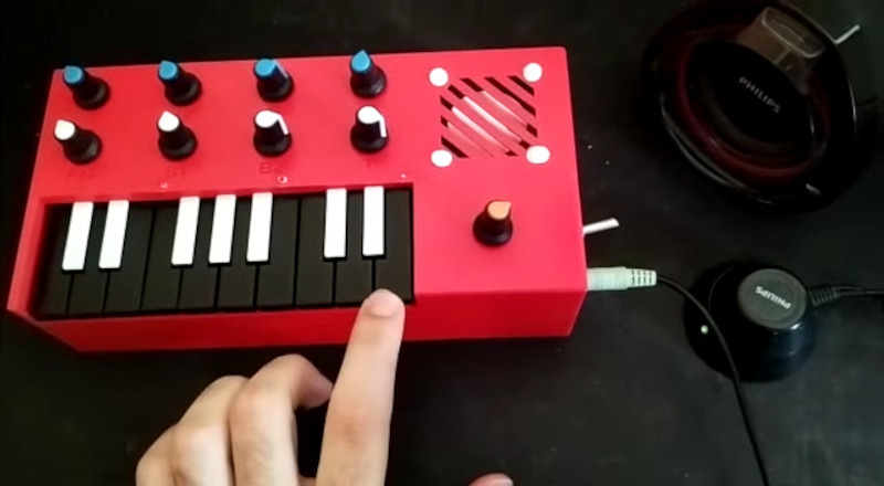
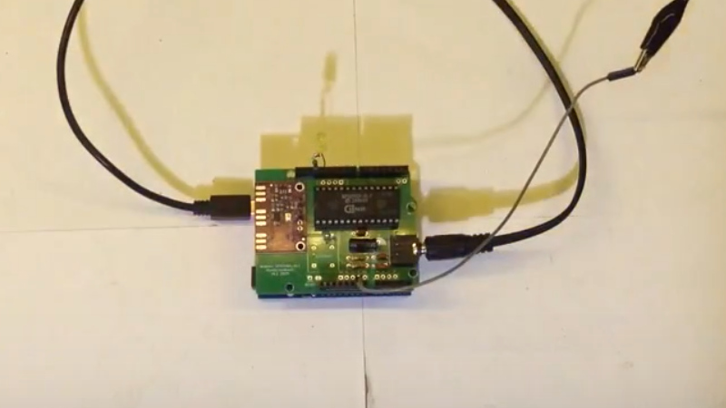
There comes a point in every Arduino’s life where, if it’s lucky, it becomes a permanent fixture in a project. We can’t think of too many better forever homes for an Arduino than inside of a 3D-printed synthesizer such as this 17-key number by [ignargomez] et al.

While there are myriad ways to synthesizer, this one uses the tried-and-true method of FM synthesis courtesy of an Arduino Nano R3. In addition to the 17 keys, there are eight potentiometers here — four are used for FM synthesis control, and the other four are dedicated to attack/delay/sustain/release (ADSR) control of the sound envelope.

One of the interesting things here is that [ignargomez] and their team were short a few regular pots and modified a couple of slide pots for circular use — we wish there was more information on that. As a result, the 3D printed enclosure underwent several iterations. Be sure to check out the brief demo after the break.

Don’t have any spare Arduinos? The BBC Micro:bit likes to make noise, too.

Kids’ Jukebox Based on Arduino with RFID

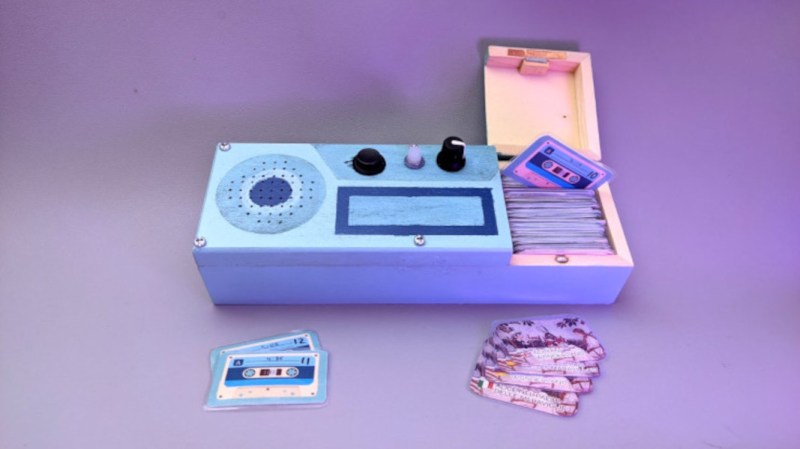
Consumer electronics aimed at young children tend to be quite janky and cheap-looking, and they often have to be to survive the extreme stress-testing normal use in this situation. You could buy a higher quality item intended for normal use, but this carries the risk of burning a hole in the pockets of the parents. To thread the needle on this dilemma for a child’s audiobook player, [Turi] built the Grimmboy for a relative of his.

Taking its name from the Brothers Grimm, the player is able of playing a number of children’s stories and fables in multiple languages, with each physically represented by a small cassette tape likeness with an RFID tag hidden in each one. A tape can be selected and placed in the player, and the Arduino at the center of it will recognize the tag and play the corresponding MP3 file stored locally on an SD card. There are simple controls and all the circuitry to support its lithium battery as well. All of the source code that [Turi] used to build this is available on the project’s GitHub page.

This was also featured at the Arudino blog as well, and we actually featured a similar project a while ago with a slightly different spin. Both are based on ideas from Tonuino, an open source project aimed at turning Arduinos into MP3 players. If you’re looking to build something with a few more features, though, take a look at this custom build based on the RP2040 microcontroller instead.

Hack a Day 17 Dec 06:00

Lo-Fi Orchestra Learns Tubular Bells

Hardware projects often fall into three categories: Those that flash lights, those that make sounds and those that move. This virtuoso performance by [Kevin]’s “Lo-Fi Orchestra” manages all three, whilst doing an excellent job of reproducing the 1973 musical classic Tubular Bells by Mike Oldfield.

Producing decent polyphonic sounds of different timbres simultaneously is a challenge for simple microcontroller boards like Arduinos, so [Kevin] has embraced the “More is more” philosophy and split up the job of sound generation in much the same way as a traditional orchestra might. Altogether, 11 Arduino Nanos, 6 Arduino Unos, an Arduino Pro Mini, an Adafruit Feather 32u4, and a Raspberry Pi running MT32-Pi make up this electronic ensemble.

Arduino Servo & Relay Drumkit

The servo & relay drumkit is a particular highlight, providing some physical sounds to go along with the otherwise solid-state generation.

The whole project is “conducted” over MIDI and the flashing sequencer in the middle gives a visual indication of the music that is almost hypnotic. The performance is split into two videos (after the break), and will be familiar to fans of 70’s music and classic horror movies alike. We’re astonished how accurately [Kevin] has captured the mood of the original recording.

If this all looks slightly familiar, it may be because we have covered the Lo-Fi Orchestra before, when it entertained us with a rousing rendition of Gustav Holst’s Planets Suite. If you’re more interested in real Tubular Bells than synthesized ones, then check out this MIDI-controlled set from 2013.

Arduino Drum Platform Is Fast

Drums are an exciting instrument to learn to play, but often prohibitive if there are housemates or close neighbors involved. For that problem there are still electronic drums which can be played much more quietly, but then the problem becomes one of price. To solve at least part of that one, [Jeremy] turned to using an Arduino to build a drum module on his own, but he still had to solve yet a third problem: how to make the Arduino fast enough for the drums to sound natural.

Playing music in real life requires precise timing, so the choice of C++ as a language poses some problems as it’s not typically as fast as lower-level languages. It is much easier to work with though, and [Jeremy] explains this in great detail over a series of blog posts detailing his drum kit’s design. Some of the solutions to the software timing are made up for with the hardware on the specific Arduino he chose to use, including an even system, a speedy EEPROM, hardware timers, and an ADC that can sample at 150k samples per second.

With that being said, the hardware isn’t the only thing standing out on this build. [Jeremy] has released the source code on his GitHub page for those curious about the build, and is planning on releasing several more blog posts about the drum kit build in the near future as well. This isn’t the only path to electronic drums, though, as we’ve seen with this build which converts an analog drumset into a digital one.

Hack a Day 29 Jun 06:00

Rotary Phone MIDI Controller Still Makes Calls

[Kevin] has long wanted to do something musical with a vintage rotary phone and an Arduino, and has finally done so and committed the first of several experiments to HTML in a five-part series. He found a nice old British Telecom number, but it had been converted to plug and socket wiring to work on the modern system. Because of this, [Kevin] wanted to keep it completely functional as a phone. After all, it ought to work fine until 2025, when pulse dialing will no longer be supported in [Kevin]’s locality.

As you can likely understand, [Kevin] was keen to interface with the phone from the outside and leave the inside untouched. He used a sacrificial ADSL filter’s PCB to break out the socket, and added a pull-up resistor between the pin and 5 V.

Pretty quickly, [Kevin] figured out that when the phone is on the hook, it gives a constant high signal, where as the picking up the phone presents as a high signal going low, and dialing each number results in pulses of that quantity that alternate between high and low.

In part two of the series, [Kevin] really gets into decoding the pulse dialing, which is necessary for the third installment when things get musical. Here, [Kevin] adds in a MIDI module and a Roland MT-32 synth to use the dial as a MIDI note generator — each note dialed will sustain until the receiver is replaced on the hook.

Part four focuses on a MIDI patch changer. [Kevin] picks up the phone, dials a code up to three digits long, and hangs up, which this triggers the synth to change to the assigned voice. In part five, the phone becomes a random note sequencer, and each successive spin of the same digit will produce a different, randomly-chosen note. This is really just the beginning, however, so we’ll be checking back for updates. In the meantime, you can listen to the note generator and the random note sequencer demos after the break.

Wouldn’t you like to use a rotary dial all the time? Well, as long as it wasn’t an emergency?

VFD Character Display Turned Into Audio VU Meter

Humans love visualising music, whether it’s in the form of an inscrutable equation drawing squiggles in Winamp, or a simple VU meter pulsing with the beat. This build from [mircemk] is of the latter variety, repurposing a VFD display to do the job.

The project is built around a VFM202MDA vacuum fluorescent display, which provides that lovely green-blue glow we all know and love, driven by a PT6314 driver chip. This has the benefit that it can be readily driven by a microcontroller in much the same way as the familiar HD44780 character LCD driver chip. With some minor tweaks, the character set can be modified to allow the display to become a surprisingly-responsive VU meter.

An Arduino Nano runs the show, with an envelope follower circuit feeding a signal for the left and right channels into the analog inputs of the microcontroller. The Arduino then measures the voltage on those inputs and feeds the necessary commands to the PT6314 driver to update the display.

The resulting VU meter has 38 bars per channel, and is highly responsive. The fast flickering of the meter bars in response to the music make it compelling to watch, and the era-appropriate enclosure the project is built in adds plenty to the aesthetic.

We’ve seen other VU meter builds before too, like this one that uses a little physics knowledge to create a more realistic analog-like needle meter. Video after the break.


Sending MIDI Wirelessly With The nRF24L01

MIDI is a standard known by musicians and instruments all over the world. The basic twist on regular serial has helped studios around the world to work more efficiently. [Kevin] wanted to try sending MIDI data wirelessly, but rather than the typical Bluetooth solution, decided to use the humble nRF24L01 instead.

The circuitry used is simple: [Kevin] simply wired up two Arduino Unos with nRF24L01 radio modules, which communicate over SPI. Alternatively, an even quicker solution is to use a Keywish Arduino RF Nano, which packs a nRF24L01 on board. One Arduino can then be hooked up to a MIDI OUT port on an instrument, and it will send out MIDI signals wirelessly. The second Arduino can then be plugged into a MIDI IN port and repeat out what it receives over the air.

The real work was in the firmware, which takes MIDI data and packages it in a suitable form to send out over the nRF24L01. The system can operate in a one-to-one mode, emulating a single MIDI cable, or a multicast mode, where one sender transmits information to many receivers.

It’s a neat hack and one we could imagine would be useful in some fun performance situations. We’ve seen others do work on wireless MIDI interfaces for Eurorack hardware, too. Video after the break.

You Can Send MIDI Over I2C If You Really Need To

The Musical Instrument Digital Interface has a great acronym that is both nice to say and cleanly descriptive. The standard for talking to musical instruments relies on a serial signal at 31250 bps, which makes it easy to transmit using any old microcontroller UART with a settable baud rate. However, [Kevin] has dived into explore the utility of sending MIDI signals over I2C instead.

With a bit of hacking at the Arduino MIDI library, [Kevin] was able to get the microcontroller outputting MIDI data over the I2C interface, and developed a useful generic I2C MIDI transport for the platform. His first tests involved using this technique in concert with Gravity dual UART modules. After he successfully got one running, [Kevin] realised that four could be hooked up to a single Arduino, giving it 8 serial UARTS, or, in another way of thinking, 8 MIDI outputs.

At its greatest level of development, [Kevin] shows off his I2C MIDI chops by getting a single Raspberry Pi Pico delivering MIDI signals to 8 Arduinos, all over I2C. All the Arduinos are daisy-chained with their 5V and I2C lines wired together, and the system basically swaps out traditional MIDI channels for I2C addresses instead.

There’s not a whole lot of obvious killer applications for this, but if you want to send MIDI data to a bunch of microcontrollers, you might find it easier daisy-chaining I2C rather than hopping around with a serial line in the classic MIDI-IN/MIDI-THRU fashion.

We’ve seen [Kevin]’s work before too, like the wonderful Lo-Fi Orchestra. Video after the break.

Hack a Day 16 Feb 06:00

Robotic Xylophone Makes Music with MIDI Magic

The MIDI format has long been used to create some banging electronic music, so it’s refreshing to see how [John P. Miller] applied the standard in his decidedly analog self-playing robotic xylophone.

Framed inside a fetching Red Oak enclosure, the 25-key instrument uses individual solenoids for each key, meaning that it has no problem striking multiple bars simultaneously. This extra fidelity really helps in reproducing the familiar melodies via the MIDI format. The tracks themselves can be loaded onto the device via SD card, and selected for playback with character LCD and rotary knob.

The software transposes the full MIDI music spectrum of a particular track into a 25-note version compatible with the xylophone. Considering that a piano typically has 88 keys, some musical concessions are needed to produce a recognizable playback, but overall it’s an enjoyable musical experience.

Perhaps most remarkable about this project is the documentation. If you want to build your own, everything you need to know is available online, and the no-solder approach makes this project very accessible. Most of the write-up happened some years ago, and we’re really interested to see what improvements have been made since.

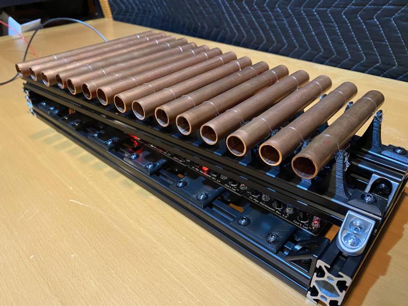
The robotic xylophone is reminiscent of these automatic tubular bells from some time ago. These musical hacks can be particularly inspiring, and we can’t wait to see more.

[Thanks Assad Ebrahim for the great tip.]