Jenny did an Ask Hackaday article earlier this month, all about the quest for a cheap computer-based audio mixer. The first attempt didn’t go so well, with a problem that many of us are familiar with: Linux applications really doesn’t like using multiple audio devices at the same time. Jenny ran into this issue, and didn’t come across a way to merge the soundcards in a single application.
I’ve fought this problem for a while, probably 10 years now. My first collision with this was an attempt to record a piano with three mics, using a couple different USB pre-amps. And of course, just like Jenny, I was quickly frustrated by the problem that my recording software would only see one interface at a time. The easy solution is to buy an interface with more channels. The Tascam US-4x4HR is a great four channel input/output audio interface, and the Behringer U-PHORIA line goes all the way up to eight mic pre-amps, expandable to 16 with a second DAC that can send audio over ADAT. But those are semi-pro interfaces, with price tags to match.
But what about Jenny’s idea, of cobbling multiple super cheap interfaces together? Well yes, that’s possible too. I’ll show you how, but first, let’s talk about how we’re going to control this software mixer monster. Yes, you can just use a mouse or keyboard, but the challenge was to build a mixing desk, and to me, that means physical faders and mute buttons. Now, there are pre-built solutions, with the Behringer X-touch being a popular solution. But again, we’re way above the price-point Jenny set for this problem. So, let’s do what we do best here at Hackaday, and build our own.
The Physical Goods
What we need is a microcontroller that has native USB client support, multiple digital I/O pins, and some analog inputs. I went with the Arduino MKRZero for the small size, decent price, and the fact that it’s actually in stock at Mouser. The other items we’ll need are some faders and buttons. I went for the full-sized 100 mm faders, and some LED toggle buttons made by Adafruit. The incidentals, like wire and resistors, was sourced from the local parts bin in the corner.
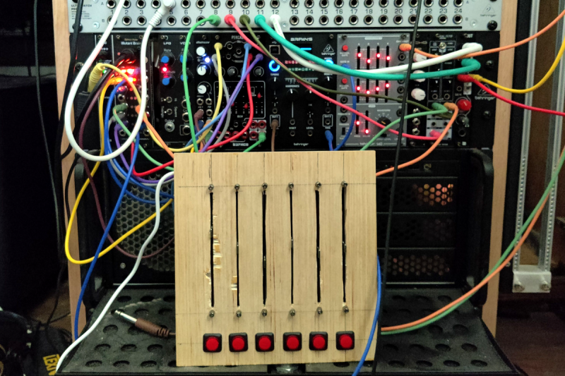
My first thought was to design and 3D print the panel, but after doing the layout on a scrap piece of plywood, the resulting size proved a bit too large for my printer. So we’re going retro, and making a “wood-grain” mixing desk. This would be a great project for a CNC router, but as I’m not part of that particular cool club yet, it was a drill press, table saw, and oscillating tool to the rescue. The results aren’t quite as pretty as I wanted, but maybe we’ll get a Mark II of this project one day.
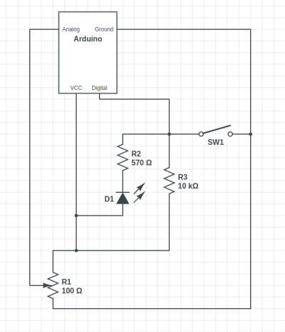
The wiring is relatively straightforward, with a current limiting resistor to protect the LEDs inside the buttons, and a pullup resistor to prevent the digital pin from floating when the button isn’t pushed. Now, that pullup might not be necessary, as I later learned that the Arduino has built-in pullup on its digital pins. And also of note, a 10 Ω resistor is *not* a good choice for a pullup. As Al eloquently put it, that’s a “pull way up resistor”. 10 kΩ is the better choice.
And to finish the build, we’ll need a sketch to run on the Arduino. Thankfully, there’s already a great library for exactly what we want to do: Control Surface. There’s a bunch of ways to set this up, but my sketch is pretty trivial:
#include <Control_Surface.h>
USBMIDI_Interface midi;

CCButtonLatching button1 {11, {MIDI_CC::General_Purpose_Controller_1, CHANNEL_1}, };
CCButtonLatching button2 {10, {MIDI_CC::General_Purpose_Controller_2, CHANNEL_1}, };
CCButtonLatching button3 {9, {MIDI_CC::General_Purpose_Controller_3, CHANNEL_1}, };
CCButtonLatching button4 {8, {MIDI_CC::General_Purpose_Controller_4, CHANNEL_1}, };
CCButtonLatching button5 {7, {MIDI_CC::General_Purpose_Controller_5, CHANNEL_1}, };
CCButtonLatching button6 {6, {MIDI_CC::General_Purpose_Controller_6, CHANNEL_1}, };

CCPotentiometer volumePotentiometers[] {
  {A0, {MIDI_CC::Sound_Controller_1, CHANNEL_1} },
  {A1, {MIDI_CC::Sound_Controller_2, CHANNEL_1} },
  {A2, {MIDI_CC::Sound_Controller_3, CHANNEL_1} },
  {A3, {MIDI_CC::Sound_Controller_4, CHANNEL_1} },
  {A4, {MIDI_CC::Sound_Controller_5, CHANNEL_1} },
  {A5, {MIDI_CC::Sound_Controller_6, CHANNEL_1} },
};
void setup() {
    Control_Surface.begin();
}
void loop() {
    Control_Surface.loop();
}
Pipewire to the Rescue
And now on to the meat and potatoes of this project. How do we convince an application to see inputs from multiple devices, and actually do some mixing? The problem here is de-sync. Each device runs on a different clock source, and so the bitstream from each may wander and go out of sync. That’s a serious enough problem that older sound solutions didn’t implement much in the way of card combining. Not long ago, the process of resampling those audio streams to get them to properly sync would have been a very CPU intensive procedure. But these days we all have multi-core behemoths, practical super-computers compared to 20 years ago.
So when Wim Taymans wrote Pipewire, he took a different approach. We have enough cycles to resample, so Pipewire will transparently do so when needed. Pipewire sees all your audio interfaces at once, and implements both the Jack and Pulseaudio APIs. Different distros handle this a bit differently, but generally you need the Pipewire packages, as well as the pipewire-jack and pipewire-pulseaudio packages to get that working.
And here’s the secret: The Jack routing tools work with Pipewire. The big three options are qjackctl, carla, and qpwgraph, though note that qpwgraph is actually Pipewire native. So even if an application can only select a single device at a time, if that app uses the Jack, Pulseaudio, or Pipewire API, you can use one of those routing control programs to arbitrary connect inputs and outputs.
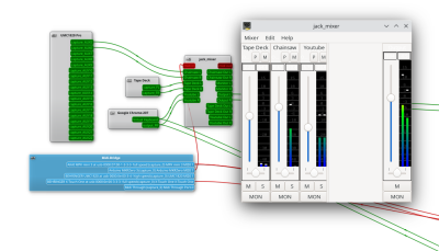
So let’s start with the simplest solution: jack_mixer. Launch the application, and then using your preferred routing controllers, take the MIDI output from our Arduino control surface, and connect it into jack_mixer‘s MIDI input. In jack_mixer, add a new input channel, and give it an appropriate name. Let’s call it “tape deck”, since I have a USB tape deck I’m testing this with. Now the controller magic kicks in: hit the “learn” button for the volume control, and wiggle the first fader on that controller. Then follow with the mute button, and save the new channel. We’ll want to add an output channel, too. Feel free to assign one of your faders to this one, too.
And finally, back to the routing program, and connect your tape deck’s output to jack_mixer input, and route jack_mixer‘s output to your speakers. Play a tape, and enjoy the full control you have over volume and muting! Want to add a Youtube video to the mix? Start the video playing, and just use the routing controller to disconnect it from your speakers, and feed it into a second channel on jack_mixer. Repeat with each of those five cheap and nasty sound cards. Profit!
You Want More?
There’s one more application to mention here. Instead of using jack_mixer, we can use Ardour to do the heavy lifting. To set it up this way, there are two primary Ardour settings, found under preferences: Under the monitoring tab make sure “Record monitoring handled by” is set to Ardour, and the “auto Input does talkback” option is checked. Then add your tracks, set the track input to the appropriate input hardware, and the track output to the master bus. Make sure the master bus is routed to where you want it, and you should be able to live mix with Ardour, too.
This gives you all sorts of goodies to play with, in the form of plugins. Want a compressor or EQ on a sound source? No problem. Want to autotune a source? X42 has a plugin that does that. And of course, Ardour brings recording, looping, and all sorts of other options to the party.
Ardour supports our custom mixing interface, too. Also under preferences, look for the Control Surfaces tab, and make sure General MIDI is checked. Then highlight that and click the “Show Protocol Settings” button. Incoming MIDI should be set to our Arduino device. You can then use the Ctrl + Middle Click shortcut on the channel faders and mute buttons, to put them in learn mode. Wiggle a control to assign it to that task. Or alternatively you can add a .map file to Ardour’s midi_maps directory. Mine looks like this:
  <?xml version="1.0" encoding="UTF-8"?>
<ArdourMIDIBindings version="1.1.0" name="Arduino Mapping">
  <Binding channel="1" ctl="16" uri="/route/mute B1"/>
  <Binding channel="1" ctl="70" uri="/route/gain B1"/>
  <Binding channel="1" ctl="17" uri="/route/mute B2"/>
  <Binding channel="1" ctl="71" uri="/route/gain B2"/>
  <Binding channel="1" ctl="18" uri="/route/mute B3"/>
  <Binding channel="1" ctl="72" uri="/route/gain B3"/>
  <Binding channel="1" ctl="19" uri="/route/mute B4"/>
  <Binding channel="1" ctl="73" uri="/route/gain B4"/>
  <Binding channel="1" ctl="80" uri="/route/mute B5"/>
  <Binding channel="1" ctl="74" uri="/route/gain B5"/>
  <Binding channel="1" ctl="81" uri="/route/mute B6"/>
  <Binding channel="1" ctl="75" uri="/route/gain B6"/>
</ArdourMIDIBindings>
The Caveats
Now before you get too excited, and go sink a bunch of money and/or time into a Linux audio setup, there are some things you should know. First is latency. It’s really challenging to get a Pipewire system set up to achieve really low latency, particularly when you’re using USB-based hardware. It’s possible, and work is ongoing on the topic. But so far the best I’ve managed to run stable is a 22 millisecond round-trip measurement — and that took a lot of fiddling with the Pipewire config files to avoid garbled audio. That’s just about usable for self monitoring and live music, and for playing anything pre-recorded, that’s perfectly fine.
The second thing to know is that this was awesome. It’s a bit concerning how much fun it is to combine some decent audio hardware with the amazing free tools that are available. Want to auto-tune your voice for your next Zoom meeting? Easy. Build a tiny MIDI keyboard into your desk? Just a microcontroller and some soldering away. The sky’s the limit. And the future is bright, too. Tools like Pipewire and Ardour are under very active development, and the realtime kernel patches are just about to make it over the finish line. Go nuts, create cool stuff, and then be sure to tell us about it!
