Posts with «computer hacks» label

Mini Meters Monitor Microprocessor Maximization

[Lex] over at Computing: The Details loves to make fun projects. Recently, he’s created a hardware CPU monitor that allows him to see how well his PC is parallelizing compile tasks at a glance. The monitor is built from 14 analog meters, along with some WS2812 RGB LEDs.

Each meter represents a core on [Lex]’s CPU, while the final two meters show memory and swap usage. The meters themselves are low-cost 5 mA devices. Of course, the original milliamps legends wouldn’t do much good, so [Lex] designed and printed graduations that glue over the top. The RGB LED strip is positioned so two LEDs fit under each meter. The LEDs allow a splash of color to draw attention to the current state of the machine. The whole bank going red would sure get our attention!

The system is controlled by an Arduino Mega, with the meters driven using the PWM pins. The only extra part is a 1 K resistor. The Arduino wrangles the LEDs as well. Sadly [Lex] did not include his software. He did describe it though. Basically he’s using a Rust program to call systemstat, obtaining the current CPU utilization data in Linux. A bit of math converts this into pointer values and LED colors. The data is then sent via USB-serial to the Arduino Mega. The software savvy will say it’s pretty easy to replicate, but the hardware only hackers among us might need a bit of help.

This isn’t the first custom meter we’ve seen on Hackaday. Your author’s first project covered by Hackaday was for a meter created using an automotive gauge stepper motor. I didn’t include source code either – but only because [Guy Carpenter]’s Switec X25 library had me covered.

Thanks for the tip, [TubeTime]!

Framework Motherboard Turned Cyberdeck

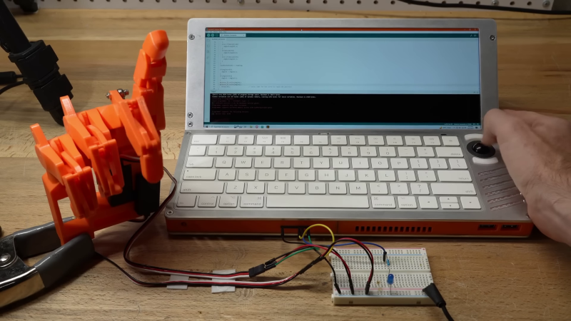
The beauty of a modular ecosystem lies in how it allows individuals to repurpose components in unconventional ways. This is precisely what [Ben Makes Everything] has achieved by using a Framework laptop’s motherboard and battery to create a slab-style cyberdeck. (Video, embedded below.)

The Framework motherboard presents an excellent choice for custom portable computer projects due to its relatively compact size and built-in modular I/O port options, all based on USB-C. Framework even released additional documentation to support this use-case. It’s significantly more powerful than the standard Raspberry PI, which is typically employed in similar projects. Ben chose a 2400 x 900 IPS display that can draw power and video through a single USB-C cable. For user input, he opted for an Apple keyboard and an optical trackball with a PS2 interface. He utilized a Arduino Pro Micro as a PS2-to-USB adaptor, using the remaining pins on the Arduino as a versatile interface for electronic projects.

The enclosure is crafted from machined aluminum plates with 3D printed spacers to secure all components. The screen can be tilted up to 45 degrees for more ergonomic desktop use. The Framework motherboard is equipped with four USB-C ports for peripheral devices; [Ben] allocated one for the display and another for a USB hub which connects the keyboard, Arduino, and external USB and HDMI connectors. The remaining USB-C ports are still available for original Framework expansion cards.

The completed project not only looks fantastic but may also be highly functional. It would have been a great entry in our recent Cyberdeck Challenge.

Hackaday Prize 2023: Building a Relay ALU

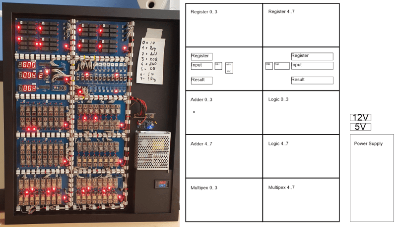
There’s much truth in the advice that, to truly understand something, you need to build it yourself from the ground up. That’s the idea behind [Christian]’s entry for the Re-engineering Education category of the 2023 Hackaday Prize. Built as an educational demonstrator, this is a complete arithmetic-logic unit (ALU) using discrete relays — and not high-density types either — these are the big honking clear-cased kind.

The design is neatly, intentionally, partitioned along functional lines, with four custom PCB designs, each board operating on 4-bits. To handle a byte-length word, boards are simply cascaded, making a total of eight. The register, adder, logic function, and multiplex boards are the heart of the build with an additional two custom boards for visualization (using an Arduino for convenience) and IO forming the interface. After all, a basic CPU is just an ALU and some control around it, the magic is really in the ALU.

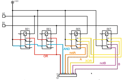
The fundamental logical operations operating upon two operands, {A, B} are A, ~A, B, ~B, A or B, A and B, A xor B, can be computed from just four relays per bit. The logic outputs do need to be fed into a 7-to-1 bit selector before being fed to the output register, but that’s the job of a separate board. The adder function is the most basic, simply a pair of half-adders and an OR-gate to handle the chaining of the carry inputs and generate the carry chain output.

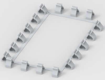
3D printed cable runs are a nice touch and make for a slick wiring job to tie it all together.

For a more complete relay-based CPU, you could check out the MERCIA relay computer project, not to mention this wonderfully polished build.


The HackadayPrize 2023 is Sponsored by:

How To Build Jenny’s Budget Mixing Desk

Jenny did an Ask Hackaday article earlier this month, all about the quest for a cheap computer-based audio mixer. The first attempt didn’t go so well, with a problem that many of us are familiar with: Linux applications really doesn’t like using multiple audio devices at the same time. Jenny ran into this issue, and didn’t come across a way to merge the soundcards in a single application.

I’ve fought this problem for a while, probably 10 years now. My first collision with this was an attempt to record a piano with three mics, using a couple different USB pre-amps. And of course, just like Jenny, I was quickly frustrated by the problem that my recording software would only see one interface at a time. The easy solution is to buy an interface with more channels. The Tascam US-4x4HR is a great four channel input/output audio interface, and the Behringer U-PHORIA line goes all the way up to eight mic pre-amps, expandable to 16 with a second DAC that can send audio over ADAT. But those are semi-pro interfaces, with price tags to match.

But what about Jenny’s idea, of cobbling multiple super cheap interfaces together? Well yes, that’s possible too. I’ll show you how, but first, let’s talk about how we’re going to control this software mixer monster. Yes, you can just use a mouse or keyboard, but the challenge was to build a mixing desk, and to me, that means physical faders and mute buttons. Now, there are pre-built solutions, with the Behringer X-touch being a popular solution. But again, we’re way above the price-point Jenny set for this problem. So, let’s do what we do best here at Hackaday, and build our own.

The Physical Goods

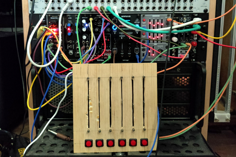
What we need is a microcontroller that has native USB client support, multiple digital I/O pins, and some analog inputs. I went with the Arduino MKRZero for the small size, decent price, and the fact that it’s actually in stock at Mouser. The other items we’ll need are some faders and buttons. I went for the full-sized 100 mm faders, and some LED toggle buttons made by Adafruit. The incidentals, like wire and resistors, was sourced from the local parts bin in the corner.

My first thought was to design and 3D print the panel, but after doing the layout on a scrap piece of plywood, the resulting size proved a bit too large for my printer. So we’re going retro, and making a “wood-grain” mixing desk. This would be a great project for a CNC router, but as I’m not part of that particular cool club yet, it was a drill press, table saw, and oscillating tool to the rescue. The results aren’t quite as pretty as I wanted, but maybe we’ll get a Mark II of this project one day.
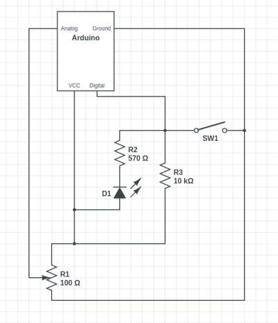
The wiring is relatively straightforward, with a current limiting resistor to protect the LEDs inside the buttons, and a pullup resistor to prevent the digital pin from floating when the button isn’t pushed. Now, that pullup might not be necessary, as I later learned that the Arduino has built-in pullup on its digital pins. And also of note, a 10 Ω resistor is *not* a good choice for a pullup. As Al eloquently put it, that’s a “pull way up resistor”. 10 kΩ is the better choice.

And to finish the build, we’ll need a sketch to run on the Arduino. Thankfully, there’s already a great library for exactly what we want to do: Control Surface. There’s a bunch of ways to set this up, but my sketch is pretty trivial:

#include <Control_Surface.h>
USBMIDI_Interface midi;

CCButtonLatching button1 {11, {MIDI_CC::General_Purpose_Controller_1, CHANNEL_1}, };
CCButtonLatching button2 {10, {MIDI_CC::General_Purpose_Controller_2, CHANNEL_1}, };
CCButtonLatching button3 {9, {MIDI_CC::General_Purpose_Controller_3, CHANNEL_1}, };
CCButtonLatching button4 {8, {MIDI_CC::General_Purpose_Controller_4, CHANNEL_1}, };
CCButtonLatching button5 {7, {MIDI_CC::General_Purpose_Controller_5, CHANNEL_1}, };
CCButtonLatching button6 {6, {MIDI_CC::General_Purpose_Controller_6, CHANNEL_1}, };
  
CCPotentiometer volumePotentiometers[] {
  {A0, {MIDI_CC::Sound_Controller_1, CHANNEL_1} },
  {A1, {MIDI_CC::Sound_Controller_2, CHANNEL_1} },
  {A2, {MIDI_CC::Sound_Controller_3, CHANNEL_1} },
  {A3, {MIDI_CC::Sound_Controller_4, CHANNEL_1} },
  {A4, {MIDI_CC::Sound_Controller_5, CHANNEL_1} },
  {A5, {MIDI_CC::Sound_Controller_6, CHANNEL_1} },
};
void setup() {
    Control_Surface.begin();
}
void loop() {
    Control_Surface.loop();
}

Pipewire to the Rescue

And now on to the meat and potatoes of this project. How do we convince an application to see inputs from multiple devices, and actually do some mixing? The problem here is de-sync. Each device runs on a different clock source, and so the bitstream from each may wander and go out of sync. That’s a serious enough problem that older sound solutions didn’t implement much in the way of card combining. Not long ago, the process of resampling those audio streams to get them to properly sync would have been a very CPU intensive procedure. But these days we all have multi-core behemoths, practical super-computers compared to 20 years ago.

So when Wim Taymans wrote Pipewire, he took a different approach. We have enough cycles to resample, so Pipewire will transparently do so when needed. Pipewire sees all your audio interfaces at once, and implements both the Jack and Pulseaudio APIs. Different distros handle this a bit differently, but generally you need the Pipewire packages, as well as the pipewire-jack and pipewire-pulseaudio packages to get that working.

And here’s the secret: The Jack routing tools work with Pipewire. The big three options are qjackctl, carla, and qpwgraph, though note that qpwgraph is actually Pipewire native. So even if an application can only select a single device at a time, if that app uses the Jack, Pulseaudio, or Pipewire API, you can use one of those routing control programs to arbitrary connect inputs and outputs.
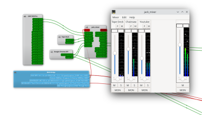
So let’s start with the simplest solution: jack_mixer. Launch the application, and then using your preferred routing controllers, take the MIDI output from our Arduino control surface, and connect it into jack_mixer‘s MIDI input. In jack_mixer, add a new input channel, and give it an appropriate name. Let’s call it “tape deck”, since I have a USB tape deck I’m testing this with. Now the controller magic kicks in: hit the “learn” button for the volume control, and wiggle the first fader on that controller. Then follow with the mute button, and save the new channel. We’ll want to add an output channel, too. Feel free to assign one of your faders to this one, too.

And finally, back to the routing program, and connect your tape deck’s output to jack_mixer input, and route jack_mixer‘s output to your speakers. Play a tape, and enjoy the full control you have over volume and muting! Want to add a Youtube video to the mix? Start the video playing, and just use the routing controller to disconnect it from your speakers, and feed it into a second channel on jack_mixer. Repeat with each of those five cheap and nasty sound cards. Profit!

You Want More?

There’s one more application to mention here. Instead of using jack_mixer, we can use Ardour to do the heavy lifting. To set it up this way, there are two primary Ardour settings, found under preferences: Under the monitoring tab make sure “Record monitoring handled by” is set to Ardour, and the “auto Input does talkback” option is checked. Then add your tracks, set the track input to the appropriate input hardware, and the track output to the master bus. Make sure the master bus is routed to where you want it, and you should be able to live mix with Ardour, too.

This gives you all sorts of goodies to play with, in the form of plugins. Want a compressor or EQ on a sound source? No problem. Want to autotune a source? X42 has a plugin that does that. And of course, Ardour brings recording, looping, and all sorts of other options to the party.

Ardour supports our custom mixing interface, too. Also under preferences, look for the Control Surfaces tab, and make sure General MIDI is checked. Then highlight that and click the “Show Protocol Settings” button. Incoming MIDI should be set to our Arduino device. You can then use the Ctrl + Middle Click shortcut on the channel faders and mute buttons, to put them in learn mode. Wiggle a control to assign it to that task. Or alternatively you can add a .map file to Ardour’s midi_maps directory. Mine looks like this:

 
  <?xml version="1.0" encoding="UTF-8"?>
<ArdourMIDIBindings version="1.1.0" name="Arduino Mapping">
  <Binding channel="1" ctl="16" uri="/route/mute B1"/>
  <Binding channel="1" ctl="70" uri="/route/gain B1"/>
  <Binding channel="1" ctl="17" uri="/route/mute B2"/>
  <Binding channel="1" ctl="71" uri="/route/gain B2"/>
  <Binding channel="1" ctl="18" uri="/route/mute B3"/>
  <Binding channel="1" ctl="72" uri="/route/gain B3"/>
  <Binding channel="1" ctl="19" uri="/route/mute B4"/>
  <Binding channel="1" ctl="73" uri="/route/gain B4"/>
  <Binding channel="1" ctl="80" uri="/route/mute B5"/>
  <Binding channel="1" ctl="74" uri="/route/gain B5"/>
  <Binding channel="1" ctl="81" uri="/route/mute B6"/>
  <Binding channel="1" ctl="75" uri="/route/gain B6"/>
</ArdourMIDIBindings>

The Caveats

Now before you get too excited, and go sink a bunch of money and/or time into a Linux audio setup, there are some things you should know. First is latency. It’s really challenging to get a Pipewire system set up to achieve really low latency, particularly when you’re using USB-based hardware. It’s possible, and work is ongoing on the topic. But so far the best I’ve managed to run stable is a 22 millisecond round-trip measurement — and that took a lot of fiddling with the Pipewire config files to avoid garbled audio. That’s just about usable for self monitoring and live music, and for playing anything pre-recorded, that’s perfectly fine.

The second thing to know is that this was awesome. It’s a bit concerning how much fun it is to combine some decent audio hardware with the amazing free tools that are available. Want to auto-tune your voice for your next Zoom meeting? Easy. Build a tiny MIDI keyboard into your desk? Just a microcontroller and some soldering away. The sky’s the limit. And the future is bright, too. Tools like Pipewire and Ardour are under very active development, and the realtime kernel patches are just about to make it over the finish line. Go nuts, create cool stuff, and then be sure to tell us about it!

Mouse Enjoys Its Freedom

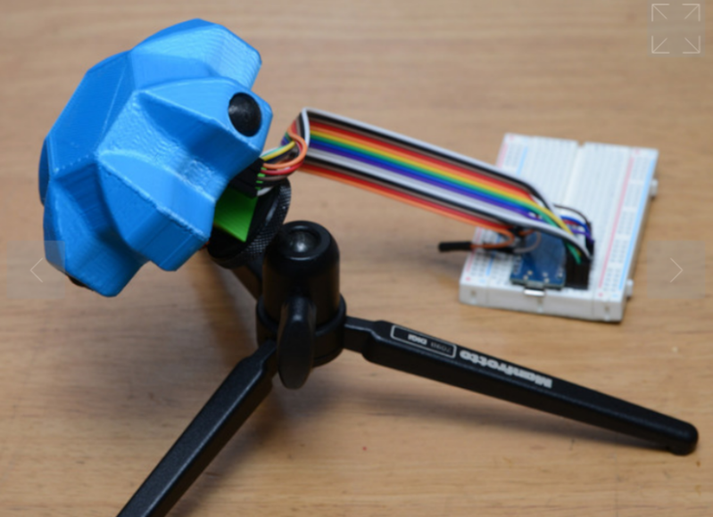
Although it took a little while to standardize on the two-button-with-scroll-wheel setup, most computers have used a mouse or mouse-like device to point at objects on the screen since the 80s. But beyond the standard “point and click” features of the mouse, there have been very few ground-breaking innovations beyond creature comforts. At least, until the “Space Mushroom” mouse from [Shinsaku Hiura] hit our tips line.

This mouse throws away most of the features a typical mouse might have in favor of a joystick-like interface that gives it six degrees of freedom instead of the usual two — while still being about mouse-sized and held in the hand. It doesn’t even have a way of mapping motion directly to movements on the screen. Instead, it maps each degree of freedom to a similar movement of the mouse itself using these three joystick sensors physically linked together, with some underlying programming to translate each movement into the expected movement on the screen.

While this might not replace a standard mouse for every use case anytime soon, it does seem to have tremendous benefit in 3D modeling software, CAD, or anything where orienting a virtual object is the primary goal. Plus, since there’s no limit to the number of mice that can be attached to a computer (beyond USB limitations) this mouse could easily be used in conjunction with a normal mouse much like macro keyboards being used alongside traditional ones.

Thanks to [Rez] for the tip!

Arduino Meets Quantum Computer

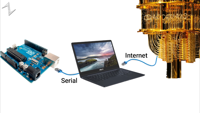
Quantum computers aren’t quite ready for the home lab, but since there are ways to connect to some over the Internet, you can experiment with them more easily than you might think. [Norbert] decided to interface a giant quantum computer to an ordinary Arduino. Why? Well, that isn’t necessarily clear, but then again, why not? He explains basic quantum computing and shows his setup in the video below.

Using the IBM quantum computer and the open source Qiskit makes it relatively easy, with the Python code he’s using on the PC acting as a link between the Arduino and the IBM computer. Of course, you can also use simulation instead of using the real hardware, and for such a simple project it probably doesn’t matter.

Granted, the demo is pretty trivial, lighting an LED with the state of qubit. But the technique might be useful if you wanted to, say, gather information from the real world into a quantum computer. You have to start somewhere.

We’ve looked at quantum computers before. They tell us it is the next big thing, so we want to be prepared. Qiskit is one of several options available today to make it easier.

Arduino IDE Creates Bootable x86 Floppy Disks

Arguably the biggest advantage of the Arduino ecosystem is how easy it is to get your code running. Type a few lines into the IDE, hit the button, and in a few seconds you’re seeing an LED blink or some text get echoed back over the serial port. But what if that same ease of use didn’t have to be limited to microcontrollers? What if you could use the Arduino IDE to create computer software?

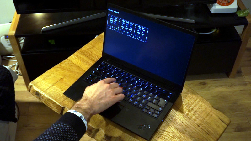
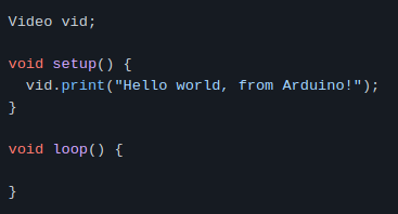
That’s exactly what boot2duino, a project developed by [Jean THOMAS] hopes to accomplish. As you might have guessed from the name, the code you write in the Arduino is turned into a bootable floppy disk image that you can stick into an old PC. After a few seconds of beeping and grinding your “Hello World” should pop up on the monitor, and you’ve got yourself the world’s biggest Arduino.

A minimal x86 Arduino sketch.

Now to be clear, this isn’t some kind of minimal Linux environment that boots up and runs a compiled C program. [Jean] has created an Arduino core that provides basic functionality on x86 hardware. Your code has full control over the computer, and there’s no operating system overhead to contend with. As demonstrated in a series of videos, programs written with boot2duino can display text, read from the keyboard, and play tones over the PC’s speaker.

The documentation for boot2duino says the project serves no practical purpose, but we’re not so sure. While the feature set is minimal, the low overhead means you could theoretically press truly ancient PCs into service. There’s certainly an appeal to being able to write your code on a modern OS and effortlessly deploy it on a retrocomputer, from somewhat modernized versions of early computer games to more practical applications. If any readers end up exploring this concept a bit further, be sure to let us know how it goes.

Build an 8-bit CPU to Know “But How Do It Know?”

Sometime around 2009, [J. Clark Scott] published a book aimed to demystify computers for everyone by walking through construction of an 8-bit CPU from scratch. The book had a catchy, but somewhat confusing title But How Do It Know?. The back story on the title goes something like this: Joe is a very nice fellow, but has always been a little slow. He goes into a store where a salesman is standing on a soapbox in front of a group of people. The salesman is pitching the miracle new invention, the Thermos bottle. He is saying, “It keeps hot food hot, and cold food cold….” Joe thinks about this a minute, amazed by this new invention that is able to make a decision about which of two different things it is supposed to do depending on what kind of food you put in it. He can’t contain his curiosity, he is jumping up and down, waving his arm in the air, saying “but, but, but, but…” Finally he blurts out his burning question “But how do it know?” Joe looked at what this Thermos bottle could do, and decided that it must be capable of sensing something about its contents, and then performing a heating or cooling operation accordingly. Joe’s concept of how the bottle worked was far more complicated than the truth. With that introductory opening, [J. Clark Scott] goes on to cover basic number theory, leading on to logic gates, and finally the 8-bit CPU.

[Patrick LeBoutillier] decided to build a hardware version of the CPU/computer as described in [John Clark Scott]’s book. In order to keep size and cost within reasonable bounds, he choose a hybrid construction using a combination of micro-controllers and SN74HC logic IC’s. When used as a companion project alongside reading the book, he hopes people can get their hands dirty and try it out for themselves. He has published a series of 14 videos covering construction of the CPU and the first Introductory video is embedded after the break below. For the micro-controller part of the project, he is using four Arduino Nanos, the code and install instructions for which are available at his Git repo. The Fritzing schematic, also available at the repo, might look a bit daunting at first look, but when you follow along his video series, it becomes easier. You can preview the first three chapters of the book at the “But How Do It Know?” website.

If FPGA’s are more of a thing for you, or you’d like to dip your feet learning FPGA, then [Patrick] has another series of 17 videos (embedded below) where he goes through the same process using a Digilent BASYS3 FPGA development board. These aren’t your only options — if you just want to understand how it works, without having to build the hardware, then check out the online, browser based implementation of the [Clark Scott] CPU.

If it seems the breadboard build of this 8-bit CPU looks complex, then this
Home Made 8-bit CPU Is A Wiry Blinky Build and a veritable rats nest of jumper wires.

Turning A Desk Drawer Into A Flight Yoke

[Christofer Hiitti] found himself with the latest Microsoft Flight Simulator on his PC, but the joystick he ordered was still a few weeks out. So he grabbed an Arduino, potentiometers and a button and hacked together what a joke-yoke.

The genius part of this hack is the way [Christopher] used his desk drawer for pitch control. One side of a plastic hinge is attached to a potentiometer inside a drawer, while the other side is taped to the top of the desk. The second pot is taped to the front of the drawer for pitch control and the third pot is the throttle. It works remarkably well, as shown in the demo video below.

The linearity of the drawer mechanism probably isn’t great, but it was good enough for a temporary solution. The Arduino Leonardo he used is based on the ATmega32u4 which has a built-in USB, and with libraries like ArduinoJoystickLibrary the computer interface very simple. When [Christopher]’s real joystick finally arrived he augmented it with a button box built using the joke-yoke components.

We’ve seen There is no doubt that Microsoft Flight Simulator 2020 will spawn a lot of great controller and cockpit builds over the next few years. We’ve already covered a new joystick build, and a 3D printed frame to turn an Xbox controller into a joystick.

Cybercube Makes a Great Computing Companion

Oh, sure, there have been a few cube-shaped PCs over the years, like the G4 and the NeXT cube. But can they really be called cubes when the display and the inputs were all external? We think not.

[ikeji] doesn’t think so either, and has created a cube PC that puts them all to shame. Every input and output is within the cube, including our favorite part — the 48-key ortholinear keyboard, which covers two sides of the cube and must be typed on vertically. (If you’ve ever had wrist pain from typing, you’ll understand why anyone would want to do that.) You can see a gif of [ikeji] typing on it after the break.

Inside the 3D printed cube is a Raspberry Pi 4 and a 5″ LCD. There’s also an Arduino Pro Micro for the keyboard matrix, which is really two 4×6 matrices — one for each half. There’s a 6cm fan to keep things cool, and one panel is devoted to a grille for heat output. Another panel is devoted to vertically mounting the microcontrollers and extending the USB ports.

Don’t type on me or my son ever again.

When we first looked at this project, we thought the tiny cube was a companion macro pad that could be stored inside the main cube. It’s really a test cube for trying everything out, which we think is a great idea and does not preclude its use as a macro pad one of these days. [ikeji] already has plenty of plans for the future, like cassette support, an internal printer, and a battery, among other things. We can’t wait to see the next iteration.

We love a good cyberdeck around here, and it’s interesting to see all the things people are using them for. Here’s a cyberduck that quacks in Python and CircuitPython.