Hewlett-Packard 5082-7415 LED Display from 1976
In this article we examine a five digit, seven-segment LED display from Hewlett-Packard, the 5082-7415:


We realise they’re most likely now pure unobtanium, but we like some old display p0rn so here you go.
2025 update – Tronixlabs in Australia has a limited quantity of new, old-stock four-digit QDSP6064 displays. Email john at tronixlabs dot com for more information.
According to the data sheet (HP 5082-series.pdf) and other research this was available for a period of time around 1976 and used with other 5082-series modules in other HP products. Such as the Hewlett-Packard 3x series of calculators, for example:

Using the display is very easy – kudos to the engineers at HP for making a simple design that could be reusable in many applications. The 5082-7415 is a common-cathode unit and wiring is very simple – there are the usual eight anodes for segments a~f and the decimal point, and the five cathodes.
As this module isn’t too easily replaceable, I was very conservative with the power supply – feeding just under 1.6V at 10mA to each of the anode pins. A quick test proved very promising:

Excellent – it worked! But now to get it displaying some sort of interesting way. Using the following hardware…
- an Arduino-compatible board
- Two 74HC595 shift registers
- Eight 560 ohm resistors
- Five 1k ohm resistors
- Five BC548 transistors
- A large solderless breadboard and plenty of wires
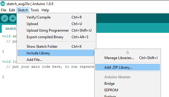
Don’t forget to use the data sheet (HP 5082-series.pdf). You don’t have to use Arduino – any microcontroller with the appropriate I/O can take care of this.
Here is a simple Arduino sketch that scrolls through the digits with and then without the decimal point:
// Arduino sketch to demonstrate HP 5082-7415 LED Display unit
// John Boxall, April 2012
int clockPin=6;
int latchPin=7;
int dataPin=8;
// array for cathodes - sent to second shift register
byte digits[]={
  B10000000,
  B01000000,
  B00100000,
  B00010000,
  B00001000,
  B11111000}; // use digits[6] to turn all on
// array for anodes (to display 0~0) - sent to first shift register
byte numbers[]={
  B11111100,
  B01100000,
  B11011010,
  B11110010,
  B01100110,
  B10110110,
  B10111110,
  B11100000,
  B11111110,
  B11110110};
void setup()
{
  pinMode(clockPin, OUTPUT);
  pinMode(latchPin, OUTPUT);
  pinMode(dataPin, OUTPUT);
}
void loop()
{
  int i;
  for ( i=0 ; i<10; i++ )
  {
    digitalWrite(latchPin, LOW);
    shiftOut(dataPin, clockPin, LSBFIRST, digits[6]);
    shiftOut(dataPin, clockPin, LSBFIRST, numbers[i]);
    digitalWrite(latchPin, HIGH);
    delay(250);
  }
  // now repeat with decimal point
  for ( i=0 ; i<10; i++ )
  {
    digitalWrite(latchPin, LOW);
    shiftOut(dataPin, clockPin, LSBFIRST, digits[6]);
    shiftOut(dataPin, clockPin, LSBFIRST, numbers[i]+1);
    digitalWrite(latchPin, HIGH);
    delay(250);
  }
}
And the results:
Now for something more useful. Here is a function that sends a single digit to a position on the display with the option of turning the decimal point on or off:
void displayDigit(int value, int posit, boolean decPoint)
// displays integer value at digit position posit with decimal point on/off
{
 digitalWrite(latchPin, LOW);
 shiftOut(dataPin, clockPin, LSBFIRST, digits[posit]);
 if (decPoint==true)
 {
 shiftOut(dataPin, clockPin, LSBFIRST, numbers[value]+1);
 }
 else
 {
 shiftOut(dataPin, clockPin, LSBFIRST, numbers[value]);
 }
 digitalWrite(latchPin, HIGH);
}
So if you wanted to display the number three in the fourth digit, with the decimal point – use
displayDigit(3,3,true);
with the following result:

We make use of the displayDigit() function in our next sketch. We introduce a new function:
displayInteger(number,cycles);
It accepts a long integer between zero and 99999 (number) and displays it on the module for cycles times:
// Arduino sketch to demonstrate HP 5082-7415 LED Display unit
// Displays numbers on request
// John Boxall, April 2012
int clockPin=6;
int latchPin=7;
int dataPin=8;
// array for cathodes - sent to second shift register
byte digits[]={
 B10000000,
 B01000000,
 B00100000,
 B00010000,
 B00001000,
 B11111000}; // use digits[6] to turn all on
// array for anodes (to display 0~0) - sent to first shift register
byte numbers[]={
 B11111100,
 B01100000,
 B11011010,
 B11110010,
 B01100110,
 B10110110,
 B10111110,
 B11100000,
 B11111110,
 B11110110};
void setup()
{
 pinMode(clockPin, OUTPUT);
 pinMode(latchPin, OUTPUT);
 pinMode(dataPin, OUTPUT);
 randomSeed(analogRead(0));
}
void clearDisplay()
// turns off all digits
{
 digitalWrite(latchPin, LOW);
 shiftOut(dataPin, clockPin, LSBFIRST, 0);
 shiftOut(dataPin, clockPin, LSBFIRST, 0);
 digitalWrite(latchPin, HIGH);
}
void displayDigit(int value, int posit, boolean decPoint)
// displays integer value at digit position posit with decimal point on/off
{
 digitalWrite(latchPin, LOW);
 shiftOut(dataPin, clockPin, LSBFIRST, digits[posit]);
 if (decPoint==true)
 {
 shiftOut(dataPin, clockPin, LSBFIRST, numbers[value]+1);
 }
 else
 {
 shiftOut(dataPin, clockPin, LSBFIRST, numbers[value]);
 }
 digitalWrite(latchPin, HIGH);
}
void displayInteger(long number,int cycles)
// displays a number 'number' on the HP display.
{
 long i,j,k,l,z;
 float f;
 clearDisplay();
 for (z=0; z
void loop()
{
 long l2;
 l2=random(0,100001);
 displayInteger(l2,400);
}
For demonstration purposes the sketch displays random numbers, as shown in the video below:
Update – four-digit versions…
They worked very nicely and can be driven in the same method as the 5082-7415s described earlier. In the following video we have run the same sketches with the new displays:
In the meanwhile, I hope you found this article of interest. Thanks to the Vintage Technology Association website and the Museum of HP Calculators for background information.
To keep up to date with new posts at tronixstuff.com, please subscribe to the mailing list in the box on the right, or follow us on x – @tronixstuff.
I hope you enjoyed reading about the displays. If you find this sort of thing interesting, please consider ordering one or more of my books from amazon.
And as always, have fun and make something.