Posts with «rotary encoder» label

DIY Arduino Hearing Test Device

Hearing loss is a common problem for many – especially those who may have attended too many loud concerts in their youth. [mircemk] had recently been for a hearing test, and noticed that the procedure was actually quite straightforward. Armed with this knowledge, he decided to build his own test system and document it for others to use.

Resultant audiogram from the device showing each ear in a different color

By using an Arduino to produce tones of various stepped frequencies, and gradually increasing the volume until the test subject can detect the tone, it is possible to plot an audiogram of hearing threshold sensitivity.  Testing each ear individually allows a comparison between one side and the other.

[mircemk] has built a nice miniature cabinet that holds an 8×8 matrix of WS2812 addressable RGB LEDs.  A 128×64 pixel OLED display provides user instructions, and a rotary encoder with push-button serves as the user input.

Of course, this is not a calibrated professional piece of test equipment, and a lot will depend on the quality of the earpiece used.  However, as a way to check for gross hearing issues, and as an interesting experiment, it holds a lot of promise.

There is even an extension, including a Class D audio amplifier, that allows the use of bone-conduction earpieces to help narrow down the cause of hearing loss further.

There’s some more information on bone conduction here, and we’ve covered an intriguing optical stimulation cochlear implant, too.

Parking Assistant Helps Back Up the Car Without Going Too Far

Sure, [Ty Palowski] could have just hung a tennis ball from the ceiling, but that would mean getting on a ladder, testing the studfinder on himself before locating a ceiling joist, and so on. Bo-ring. Now that he finally has a garage, he’s not going to fill it with junk, no! He’s going to park a big ol’ Jeep in it. Backwards.

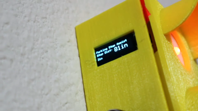
The previous owner was kind enough to leave a workbench in the rear of the garage, which [Ty] has already made his own. To make sure that he never hits the workbench while backing into the garage, [Ty] made an adorable stoplight to help gauge the distance to it. Green mean’s he’s good, yellow means he should be braking, and red of course means stop in the name of power tools.

Inside the light is an Arduino Nano, which reads from the ultrasonic sensor mounted underneath the enclosure and lights up the appropriate LED depending on the car’s distance. All [Ty] has to do is set the distance that makes the red light come on, which he can do with the rotary encoder on the side and confirm on the OLED. The distance for yellow and green are automatically set from red — the yellow range begins 24″ past red, and green is another 48″ past yellow. Floor it past the break to watch the build video.

The humble North American traffic signal is widely recognized, so it’s a good approach for all kinds of applications. Teach your children well: start them young with a visual indicator of when it’s okay to get out of bed in the morning.

Multi-Volume Knob Gives All Your Programs a Turn

We’ve all been there. You’re manning the battle station, deep in the sim-racing or some other n00b-pwning zone and suddenly some loudmouth blows out your eardrums over Discord. It’s insulting to have to stop what you’re doing to find the right Windows volume slider. So why do that? Build [T3knomanzer]’s simple yet elegant multi-volume knob and stay zen in the zone.

It’s easy, just turn the knob to cycle through your programs until Discord comes up on the little screen, and then push down to change it into a volume knob. If you need to change another volume, just click it again. Since there’s no Alt+Tabbing out to the desktop, no checkered flags should ever slip through your fingers.

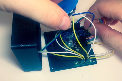
Inside the well-designed case you’ll find the usual suspects — Arduino Nano, rotary encoder, an OLED display, and an LED ring, each with their own place carved out.

This completely open-source knob looks great, and we love that it’s been made incredibly easy to replicate by standing up a site with foolproof, well-depicted, step-by-step instructions. Watch them take it for a spin after the break.

Want more than volume at your fingertips? Here’s a DIY USB knob that does shortcuts, too.

Software Shortcut Keyboard Registers Many Macros

[FabroLabs Technologies] is an industrial designer who uses several creative-type software programs in a given day. Unfortunately, they all have slightly different shortcut schemes, and trying to remember all the different modifiers is a waste of time better spent elsewhere.

This lovely little macro keyboard is every bit as useful as it is cool looking. Spinning the rotary encoder cycles through a menu of programs on the 16×2 LCD, and the key map just updates automatically for the chosen program. At the heart of this build is an Arduino Pro Micro and 20 of the loudest key switches ever made — Cherry MX blues. We like that it manages to look like toy cash register and a serious peripheral all at once — it probably has something to do with those way-cool circular keycaps that were made on a resin printer.

We’re glad that [FabroLabs] laid down such a comprehensive and open build guide during the process of making this macro keyboard. The average hacker can learn a lot from industrial designers who show their work. Remember the time [Eric Strebel] showed us all how to improve our foam board design game?

Spot This DIY Electronic Load’s Gracefully Hidden Hacks

Sometimes it’s necessary to make do with whatever parts one has on hand, but the results of squashing a square peg into a round hole are not always as elegant as [Juan Gg]’s programmable DC load with rotary encoder. [Juan] took a design for a programmable DC load and made it his own in quite a few different ways, including a slick 3D-printed enclosure and color faceplate.

The first thing to catch one’s eye might be that leftmost seven-segment digit. There is a simple reason it doesn’t match its neighbors: [Juan] had to use what he had available, and that meant a mismatched digit. Fortunately, 3D printing one’s own enclosure meant it could be gracefully worked into the design, instead of getting a Dremel or utility knife involved. The next is a bit less obvious: the display lacked a decimal point in the second digit position, so an LED tucked in underneath does the job. Finally, the knob on the right could reasonably be thought to be a rotary encoder, but it’s actually connected to a small DC motor. By biasing the motor with a small DC voltage applied to one lead and reading the resulting voltage from the other, the knob’s speed and direction can be detected, doing a serviceable job as rotary encoder substitute.
The project’s GitHub repository contains the Arduino code for [Juan]’s project, which has its roots in a design EEVblog detailed for an electronic load. For those of you who prefer your DIY rotary encoders to send discrete clicks and pulses instead of an analog voltage, a 3D printed wheel and two microswitches will do the job.

Stepper motor utilized as a rotary encoder with Arduino

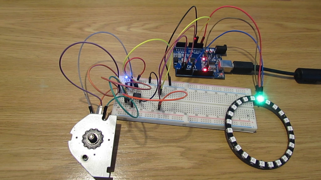
Stepper motors work by alternating a series of magnets in order to rotate its shaft by a certain angle. When the shaft is manually twisted, these magnets produce an electrical signal in a predictable pattern, which as shown in the video below, can be used as an encoder with the help of an Arduino Uno.

More information, including a circuit diagram and the Arduino code used for the stepper-NeoPixel and stepper-stepper examples can be found here. While the write-up notes that this stepper-encoder won’t work reliably if turned too slowly, it seems to work quite well at the fairly low speed shown in the demonstrations.

I want to tell you how to make incremental encoder from stepper motor. When we turning shaft of stepper motor it works like generator. It generates certain impulses on its coils. After some signal processing, we get same impulses as incremental encoder. This encoder has one problem, it can drop steps if you turning very slowly. But for many applications, it doesn’t matter.

Man-in-the-Middle Jog Pendant: Two Parts Make Easier Dev Work

In a project, repetitive tasks that break the flow of development work are incredibly tiresome and even simple automation can make a world of difference. [Simon Merrett] ran into exactly this while testing different stepper motors in a strain-wave gear project. The system that drives the motor accepts G-Code, but he got fed up with the overhead needed just to make a stepper rotate for a bit on demand. His solution? A grbl man-in-the-middle jog pendant that consists of not much more than a rotary encoder and an Arduino Nano. The unit dutifully passes through any commands received from a host controller, but if the encoder knob is turned it sends custom G-Code allowing [Simon] to dial in a bit acceleration-controlled motor rotation on demand. A brief demo video is below, which gives an idea of how much easier it is to focus on the nuts-and-bolts end of hardware when some simple motor movement is just a knob twist away.
[Simon]’s jog pendant moves a single motor which is exactly what he needs to ease development of his 3D printed strain-wave gear using a timing belt, but it could be programmed with any G-Code at all. Speaking of DIY jog pendants for CNC machines, don’t forget this wireless one made from an Atari 2600 joystick that jogs a plasma cutter in X and Y, and zeroes it with a push of the button.


Filed under: Arduino Hacks, cnc hacks

Wheel of Resistors Form Unique Rotary Encoder

Continuing his tradition of making bits of wire and scraps of wood work wonders, [HomoFaciens] is back with a unique and clever design for an electromechanical encoder.

There are lots of ways to build an encoder, and this is one we haven’t seen before. Not intended in any way to be a practical engineered solution, [HomoFaciens]’ build log and the video below document his approach. Using a rotating disc divided into segments by three, six or eight resistors, the encoder works by adding each resistor into a voltage divider as the disc is turned. An Arduino reads the output of the voltage divider and determines the direction of rotation by comparing the sequence of voltages. More resistors mean higher resolution but decreased maximum shaft speed due to the software debouncing of the wiped contacts. [HomoFaciens] has covered ground like this before with his tutorial on optical encoders, but this is a new twist – sort of a low-resolution continuous-rotation potentiometer. It’s a simple concept, a good review of voltage dividers, and a unique way to sense shaft rotation.

Is this all really basic stuff? Yep. Is it practical in any way? Probably not, although we’ll lay odds that these encoders find their way into a future [HomoFaciens] CNC build. Is it a well-executed, neat idea? Oh yeah.


Filed under: misc hacks

Dial is a Simple and Effective Wireless Media Controller

[Patrick] was looking for an easier way to control music and movies on his computer from across the room. There is a huge amount of remote control products that could be purchased to do this, but as a hacker [Patrick] wanted to make something himself. He calls his creation, “Dial” and it’s a simple but elegant solution to the problem.

Dial looks like a small cylindrical container that sits on a flat surface. It’s actually split into a top and bottom cylinder. The bottom acts as a base and stays stationary while the top acts as a dial and a push button. The case was designed in SOLIDWORKS and printed on a 3D printer.

The Dial runs on an Arduino Pro mini with a Bluetooth module. The original prototype used Bluetooth 2.0 and required a recharge after about a day. The latest version uses the Bluetooth low energy spec and can reportedly last several weeks on a single charge. Once the LiPo battery dies, it can be recharged easily once plugged into a USB port.

The mechanical component of the dial is actually an off-the-shelf rotary encoder. The encoder included a built-in push button to make things easier. The firmware is able to detect rotation in either direction, a button press, a double press, and a press-and-hold. This gives five different possible functions.

[Patrick] wrote two pieces of software to handle interaction with the Dial. The first is a C program to deal with the Bluetooth communication. The second is actually a set of Apple scripts to actually handle interaction between the Dial and the various media programs on his computer. This allows the user to more easily write their own scripts for whatever software they want. While this may have read like a product review, the Dial is actually open source!


Filed under: Arduino Hacks, peripherals hacks

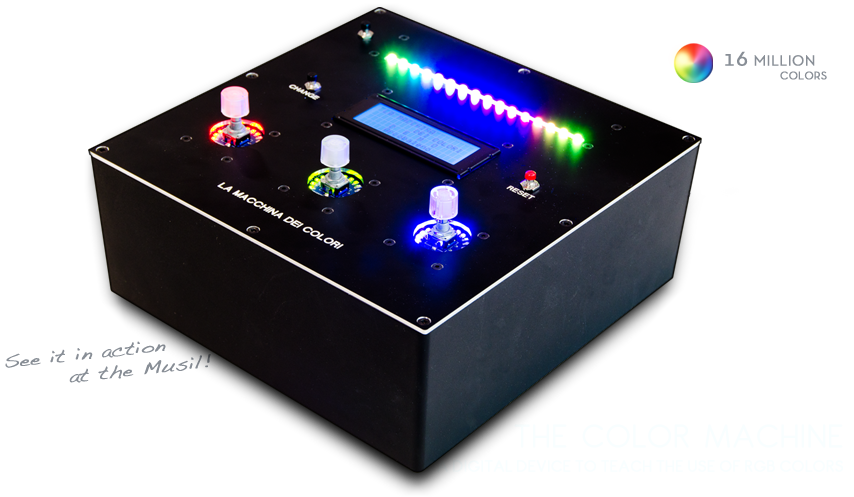
Teach kids how colors are made with the color machine

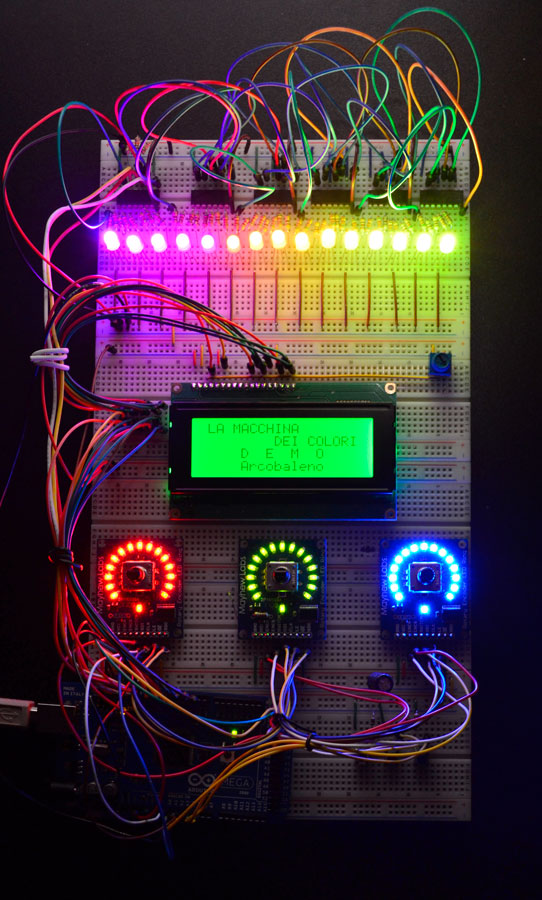
The Color Machine (La macchina dei colori, in Italian language) is a tool to teach children about the use and the operation of RGB color coding, which is used in all digital devices (TVs, smartphones, computers, etc.). It was created with Arduino Mega by an italian duo composed by Fabio Ghidini and Stefano Guerrini:

Using 3 knobs you can increase the percentages of red, green and blue separately, and the LED strip at the top of the machine lights up consistently with the color mix choosen.

The Color Machine has 4 different operating modes: “let’s create colors”, “guess the color”, “the names of the colors” and “demo”. Under the guidance of a teacher, children can play and learn at the same time to recreate colors with additive synthesis. This device is currently used in the educational workshops of Musil – Museum of Industry and Labour of Rodengo Saiano (Italy).


This is the first propotype:

Arduino Blog 09 Apr 11:05