Posts with «kl25z» label

Arduino-compatible software for FRDM-KL25Z board

As many of you have realized, I’m finding that doing multiple-platform support for the PteroDAQ system is a bit annoying.  One irritation is that the mbed.org compiler for the FRDM-KL25Z board is not integrated with the other compilers—not even sharing the same file system.  So every time I make a change, I need to transfer all the files between my laptop and the mbed website—I can’t use mercurial or git to keep things in sync.

All the other boards I’m using can be compiled for locally and downloaded to with the Arduino IDE.  It is not a particularly powerful IDE, but it is dead simple to use, and it runs on my old Mac OS 10.6.8 (at least, if I use Arduino 1.0.6—the newer versions seem to assume new Macs).  A lot of the “professional” IDEs assume that you replace your computer every year and have the latest OS installed, or that you use nothing but Windows.

Since the FRDM KL25Z board is currently one of the best price/feature microcontroller boards on the market, I figured that someone must be working on an Arduino plug-in for the hobbyist market.  So I did some Google searches and found something that initially looked promising: Arduino-compatible software library for FRDM-KL25Z board – CodeProject.

FRDM-KL25Z is an interesting ultra low cost board with 32-bit microcontroller. What makes it interesting for the Do-It-Yourself community is low price (about $13) and also the compatibility with the Arduino pinout. If you are Arduino user like me, you will probably also feel interest if you hear about a board which could, for less than half the price of standard Arduino board, give you a 32-bit ARM MCU running at 48 MHz with 128 KB of FLASH and 16 KB of RAM memory, on-board accelerometer and more. But as you might have expected, there is a “catch”. The  FRDM board has the same layout of pins, so you can connect the Arduino shields to it, but there is no software compatibility. You cannot use the Arduino API functions such as digitalRead, delay, etc. and you cannot program the board from the Arduino IDE. I was thinking it would be nice if you could… And this article is my first step in this direction.

Digging deeper, though, disappointed me.  They are trying to provide the trivial parts of the Arduino API, but they do their compiling with Kinetis Design Studio (which doesn’t run on Mac OS 10.6.8, and which is supposedly a bit of a bear to learn to use).  I’m more interested in the opposite combination—using the Arduino IDE, with only minimal use of the Arduino API (which I find a bit too inefficient for my tastes), except for a couple of difficult things (like the USB stack).

They’ve also licensed their code with a contagious LGPL license, which is too restrictive for the PteroDAQ code.

What I’m looking for is something like the Teensyduino implementation, but for the FRDM KL25Z board. I’ll have to look at how the Teensy loader is integrated into the Arduino IDE—if I can figure out how to put in copying a .bin or .s19 file to an emulated flash drive instead, then I can probably program for the KL26Z board, and possibly for the KL25Z board.


Filed under: Circuits course Tagged: Arduino, KL25Z, KL26Z, PteroDAQ, Teensy

PteroDAQ boards

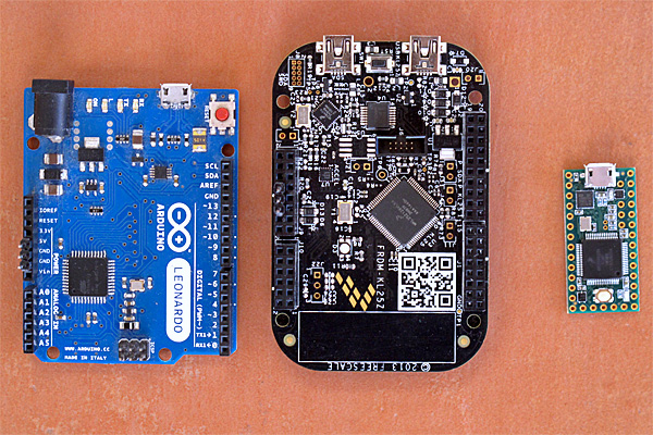
I took a photograph this afternoon of three of the boards that can be used with the PteroDAQ data acquisition system:

On the left is the Arduino Leonardo, the slowest and most expensive of the boards here. In the middle is the KL25Z, which I’ve been using in my class for a couple of years—it is the cheapest and most featureful of the boards. On the right is the Teensy 3.1 (without headers yet), which is the fastest and smallest of the supported boards.

I’m considering switching to the Teensy 3.1 for the class, despite its higher price than the KL25Z board, because adding male headers to the bottom of the board makes it possible to plug the Teensy 3.1 into a bread board, which makes for more secure wiring than running separate wires to the KL25Z board.  We don’t really need the 64 pins of the KL25Z board, we’re not mounting Arduino shields, and we’re not using the accelerometer or the touch sensor, so the main question is whether it is better to have the data-acquisition board be standalone or be inserted into a bread board. The RGB light on the KL25Z board is a nice feature for providing feedback that is missing from the other boards (which only have a single-color LED).

I’ve also thought about usefulness to the students after the course, though few of the students will go on to do anything other than PteroDAQ with the boards.  The Arduino IDE is much easier to deal with for beginners than any of the development environments for the KL25Z, and Teensyduino is pretty easy to install on top of the Arduino environment.  So if students are going to go on to do hobbyist-level programming on the boards, then an Arduino board or the Teensy 3.1 might be a better choice. Given how much more powerful the Teensy 3.1 is than the old ATMega-based Arduinos, I see no reason to recommend buying Arduino boards (though clones from China have gotten down to about $3).

Erich Styger, in a comment, mentioned that he is frustrated by the Teensy’s lack of a SWD (serial wire debug) connector, which he is used to using for debugging. Since I’m from an older generation of programmers, I don’t miss it—I’ve not used the SWD connector on the KL25Z boards (though my son has, to use the OpenSDA chip as a programmer).  For me, it is a luxury to have a serial port for getting print messages from the board—I started microprocessor programming in the days when having one or two LEDs was about all the information you got back from the board. Having debuggers like GDB was a luxury available on computers that cost thousands of dollars.

Of course, the ARM processors on the Teensy 3.1 and the FRDM KL25Z boards are very much more complicated than the old 8080A, Z80, and 6800 8-bit processors I started with, and people are writing much larger programs for them, so I can see the advantage of having a debugger. But there is a large startup cost to learning to use a debugger and setting up the complicated software development tools they expect you to use, so I’m happy recommending the very limited, but easy-to-use Arduino interface for bioengineering students who want to go a bit further.

I’m curious what my readers think about the choice between a FRDM KL25Z board and a Teensy 3.1 board for the Applied Electronics class, given that most of the students will only use the boards for that class.  What tradeoffs might I have missed?  If you were in the class, which board would you rather work with?


Filed under: Circuits course, Data acquisition Tagged: Arduino, debugger, KL25Z, Leonardo, PteroDAQ, Teensy

PteroDAQ supports Teensy 3.1

In one day my son and I added support for the Teensy 3.1 board to the PteroDAQ data acquisition system that previously supported the Freedom KL25Z board and the ATMega-based Arduino boards.

We ended up using the Teensyduino development system, but really only for the downloading and for the usb-serial library, since the K20 ARM chip on the Teensy 3.1 is quite similar to the KL25 that we originally based things on.

The Teensy 3.1 is a lot easier to install the software on than the Freedom boards, and runs a little faster (72MHz instead of 48MHz), but has essentially the same ADC.  Actually, it has 2 analog-to-digital converters, but most of the pins can only be read by ADC0, so we’ve not set up ADC1 to read anything but the internal 1.2V Vref (which is conveniently provided as an output on the AREF pin).  We had originally planned to use just ADC0, but the code for reading the Vref signal on ADC0 never worked—I suspect an error in the reference manual, since changing to reading Vref with ADC1 worked fine.

The Freedom boards are cheaper, are easier to unplug the USB cables from, can deliver more power at 3.3V, have RGB LED, and have a lot of neat features missing from the Teensy boards, but the Teensy boards can be configured to plug directly into a bread board (if you give up a lot of the connections and just use 26 pins), and have more RAM (so can run for longer at high sampling rates before the buffer overflows).

I’m going to have to rewrite part of my book to talk about the possibility of using the Teensy 3.1, and I’ll have to decide whether the extra $6–$7 is worth the simpler setup for my Applied Electronics lab course. We’d sacrifice being able to get much power from the board (probably only about 100mA instead of 500mA at 3.3V), but that is a relatively minor loss, since we have bench power supplies at every station.

I’m not sure what I’ll recommend in the book for people trying to learn on their own—I’ll probably have to play with the Teensy a bit to see how useful it is.  I have at least one other program that the students have been using in the lab (the frequency detector for turning a relaxation oscillator into a touch sensor) that I’ll have to port to Arduinos and the Teensy 3.1.

For home hobbyists who aren’t planning to dive deep into embedded-system programming, the Teensyduino IDE is a lot friendlier than the MBED.ORG tools (and I hear that the Kinetis SDK has a very, very large learning curve), so it might be a better board despite the lack of peripherals (no accelerometer, RGB LED, or capacitive touch slider).


Filed under: Circuits course, Data acquisition Tagged: Arduino, data acquisition, KL25Z, PteroDAQ, Teensy

PteroDAQ board calibration

Yesterday, while I was in the circuits lab, I checked the calibration of the voltage references on the KL25Z boards and the 4 Arduino boards I had with me.

What I did was to measure the power-supply voltage on the board with a good multimeter and make several of the PteroDAQ self-calibrations of the reference voltage (v0.2b1 does a new calibration every time the “pause” button is pressed).

For the KL25Z board, the voltage regulator on the board was well calibrated—I got a reading of 3.3001V with the bench multimeter.  The 33 PteroDAQ calibrations I recorded gave an average reading of 3.3095V with a standard deviation of 400.6µV. That means that the PteroDAQ reported voltages will be about 0.28±0.01% too high (much better than the ±3% specification for the bandgap voltage reference on the chip).   This is probably better than any of the cheap meters I have at home.

For the Arduino boards, the reference is normally the USB 5V power supply, which was not stable enough to do these comparisons with—I couldn’t get a constant reading on the good voltmeters but saw fluctuations of almost 10mV.  I should have had a 9V wall-wart power supply with me, so that I could get a more stable voltage source from the on-board regulators, but lacking that, I used a bench power supply directly connected to the +5V and Gnd pins of the Arduino to force specific voltages around 5V and did the same comparisons as for the KL25Z board.

board measurements voltage reading
KL25Z 33 +0.28±0.01%
Sparkfun Redboard 10 +0.08±0.10%
Duemilanove  11 –0.26±0.15%
Leonardo  10 –1.81±0.13%
Uno  8 +1.68±0.05%%

The greater fluctuation for the Arduino boards is probably due to the lower resolution of the ADC—the 10-bit ADC should have a reading around 225 at 1.1V with a 5V reference, so ±0.15% is only ±1/3 LSB.  The ATMega chips are guaranteed to have ±10% accuracy on the bandgap reference, but that is over the full temperature range, so ±2% seems about right for room temperature.

The USB power-supply is not a constant voltage, and the fluctuation in the USB power-supply voltage (which can be as much as ±10%) is a problem when using the Arduino boards, so powering them off of a wall wart is a good idea when trying to measure signals accurately.

The voltage measurements are as good as with super-cheap handheld voltmeters (which generally have a specification of about ±1%), so the PteroDAQ system is good enough for first electronics courses and hobbyist labs.


Filed under: Circuits course, Data acquisition Tagged: Arduino, Bandgap voltage reference, data acquisition, KL25Z, PteroDAQ

PteroDAQ v0.2b1 released!

For the past couple of years, I’ve been using the PteroDAQ data acquisition system that my son wrote for the KL25Z board (a second-generation system, replacing the earlier Arduino Data Logger he wrote). Over the past week, he has been transferring the project to me, and together we did a lot of debugging and enhancements.

Today, we tested the code on the ancient Windows 7 machines in the circuits lab at UCSC (we only have Mac OS 10 and Linux at home), and decided it was ready for a beta release.

The new code is way better than the old code! Here are a few of the bigger changes:

  • We now support all the ATMega-based Arduino boards, while still supporting the KL25Z.  The KL25Z board is a better choice for a new user, since it is cheaper and has a much better analog-to-digital converter than the Arduinos, but there are a lot of Arduinos and Arduino clones already in hobbyist hands, and PteroDAQ now works for them with no new hardware.
  • Sampling rates have improved enormously, particularly for the KL25Z and the Leonardo Arduino boards, which have USB serial communication without the bottleneck of a UART, but even the UART-based Arduino boards have a decent throughput of 2600Hz for a single analog channel. Leonardo gets 5370Hz, and the KL25Z is limited by the Python program on the host—7.8kHz on the old Windows machines, almost 10kHz on my old MacBook Pro (buffer overflow in the operating system loses some packets after a million samples), and about 19kHz on my son’s Linux laptop (again starting to lose samples after about 1 million).  That’s not fast enough for high-quality audio, but it would do for speech-quality audio. It’s a lot better than the old v0.1 PteroDAQ, which was much more limited by the host, having trouble getting even 180Hz on the old Windows machines.
    For short stretches, PteroDAQ can run somewhat faster—I can get 15kHz for about 400,000 samples on my MacBook Pro, which is long enough for a lot of lab experiments.
  • We’ve removed the need for PySerial. My son reimplemented the USB serial interface (based heavily on the PySerial implementation), so that we could have everything in a single download with no dependencies outside the standard modules that come with Python.  The implementation may still be a bit inefficient (like the PySerial one), and we are considering working on it.
  • Sparklines for the different signals now scroll smoothly even at the highest sampling rates, without taking up much of the host processor.
  • Most recent data for each channel is shown numerically next to the channel (which is particularly useful when doing single samples).
  • Resizing the window now works well, shrinking and stretching in the appropriate places.
  • The GUI now reports errors when PteroDAQ can’t keep up with the requested sampling rate, which makes trading off the sampling rate and averaging easier.

The speed limitations are partly in how fast the Python program on the host machine can accept and process the data, and partly in how fast the KL25Z or Arduino board can do the analog-to-digital conversion. The Arduino boards hit the conversion limits before any of the host machines we used ran into Python limitations, but the KL25Z board with 1× averaging can produce data faster than any of our machines can accept it, so there is still work to be done on improving the efficiency of the Python code.

The software now needs a few users to test it out and find out what problems remain. Some things we won’t be able to do anything about—if Python crashes or the operating system messes up the communication link, there isn’t a lot we can do. Some things are not worth our time (like internationalizing the interface—though we do plan to get unicode characters properly handled in the Notes field—getting that to work in both Python2 and Python3 may be a bit tricky).

I encourage any one who has an Arduino or KL25Z board to try out the new system and tell what problems they have (other than the dire lack of documentation, which I will try to work on with my son over the summer). Ideas for new features are welcome also, though probably won’t come soon.

The software was a complete refactoring of the previous code, with much cleaner interfaces between the modules, which should help with maintenance and extension in future.  I have a huge wish list for new features to add to PteroDAQ, but my son needs to get back to work on the new product for Futuristic Lights, and I need get back to work on my book, so I’ll mainly be putting ideas onto the issue tracker, with the intent of getting back to them later.


Filed under: Circuits course, Data acquisition Tagged: Arduino, data acquisition, KL25Z, PteroDAQ, sampling frequency

Improving PteroDAQ

For the past couple of years, I’ve been using the PteroDAQ data acquisition system that my son wrote for the KL25Z board (a second-generation system, replacing the earlier Arduino Data Logger he wrote).  He has been working on and off on a multi-platform version of PteroDAQ for over a year, and I finally asked him to hand the project over to me to complete, as I want it much more than he does (he’d prefer to spend his time working on new products for his start-up company, Futuristic Lights).

It has been a while since he worked on the code, and it was inadequately documented, so we’ve been spending some time together just digging into the code to figure out the interfaces, which I’ve been adding comments and docstrings to, so that I can debug the code.  Other than the lack of documentation, the code is fairly well written, so figuring out what is going on is not too bad (except in the GUI built using tkinter—like all GUI code, it is a complicated mess, because the APIs for building GUIs are a complicated mess).

The man goal of his multi-platform code was to support Arduino ATMega-based boards and the KL25Z board, while making it relatively easy to add more boards in future.  The Arduino code is compiled and downloaded by the standard Arduino IDE, while the KL25Z board code is compiled and downloaded with the MBED online compiler.  He has set up the software with appropriate #ifdef checks, so that the same code files can be compiled for either architecture.  The knowledge of what features are available on each board and how to request them is stored in one module of the python program that runs on the host computer.  As part of the cleaning up, we’ve been moving some of the code around to make sure that all the board-specific stuff is in that file, with a fairly clean interface.

He believed that he had gotten the new version working on the Arduino boards, but not on the KL25Z board.  It turned out that was almost true—I got the system working with the Leonardo board (which uses USB communication and has a weird way to get reset) almost immediately, but had to do a number of little bug fixes to get it working with other Arduino boards (which use UART protocol and a different way of resetting). It turned out that the system also worked with the KL25Z after those bug fixes, so he was very close to having it ready to turn over to me.

One of the first things I did was to time how fast the boards would run with the new code—the hope was that the cleaner implementation would have less overhead and so support a higher sampling rate.  Initial results on the Arduino boards were good, but quite disappointing on the KL25Z boards, which use a faster processor and so should be able to support much higher speeds.  We tracked the problem down to the very high per-packet overhead of the USB packets in the mbed-provided USBSerial code.  (He had tried writing his own USB stack for bare-metal ARM, but had never gotten it to work, so we were using the mbed code despite its high overhead.)

There was a simple fix for the speed problem: we stopped sending single-character packets and started using the ability of the MBED code (and the Arduino code for the Leonardo) to send multi-character packets.  With this change, we got much better sampling rates (approximate max rate):

channels Leonardo Uno/Duemilanove/Redboard KL25Z 32x avg KL25Z, 1x avg
0  13kHz  4.5kHz  8.2kHz
1 analog  5kHz  2.7kHz  5.5kHz  8.1kHz
2 analog  3kHz  1.9kHz  3kHz  8.1kHz
7 digital  6.5kHz  3.4kHz  8.2kHz

It is interesting that the Leonardo (a much slower processor) manages to get a higher data rate than the KL25Z when sending just time stamps.  I think that I can get another factor of 3 or 4 speed on the KL25Z by flushing the packets less often, though, so I’ll try that.

By flushing only when needed, I managed to improve the KL25Z performance to

channels KL25Z 32x avg KL25Z, 1x avg
0  17kHz
1 analog  6.3kHz  10kHz ??
2 analog  3.3kHz

Things get a bit hard to measure above 10kHz, because the board runs successfully for several hundred thousand samples, then I start losing characters and getting bad packets. The failure mode using my son’s faster Linux box is different: we lose full packets when going too fast—which is what PteroDAQ is supposed to do—and the speed at which the failure starts happening is much higher (maybe 23kHz). In other words, what I’m seeing now are the limitations of the Python program on my old MacBook Pro. It does bother me that the Mac seems to be quietly dropping characters when the Python program can’t clear the USB serial input fast enough.

The KL25Z slows down when doing the 32x hardware averaging, because the analog-to-digital conversion is slow—particularly when doing 32× hardware averaging.  I think that we’ve currently set things up for a 6MHz  ADC clock, with short sampling times, which means that a single-ended 32× 16-bit conversion takes around 134µs and the sampling rate is limited by the conversion times (differential measurements are slower, around 182µs).

There is a problem in the current version of the code, in that interrupts that take longer to service than the interrupt time result in PteroDAQ lying about its sampling rate.  I can fix this on the KL25Z by using a separate timer, but the Arduino boards have rather limited timer resources, and we may just have to live with it on them.  At least I should add an error flag that indicates when the sampling rate is higher than board can handle.

We had a lot of trouble yesterday with using the bandgap reference to set the voltage levels.  It turns out that on the Arduino boards, the bandgap channel is a very high impedance, and it takes many conversion times before the conversion settles to the final value (nominally 1.1V).  Switching channels and then reading the bandgap is nearly useless—the MUX has to be left on the bandgap for a long time before reading the value means anything.  If you read several bandgap values in quick succession, you can see the values decaying gradually from the value of the previously read channel to the 1.1V reference.

The bandgap on the KL25Z is not such a high-impedance source, but there is some strange behavior when reading it with only 1× averaging—some values seem not to occur and the ds.  I recorded several thousand measurements with 1×, 4×, 8×, 16×, and 32× averaging:
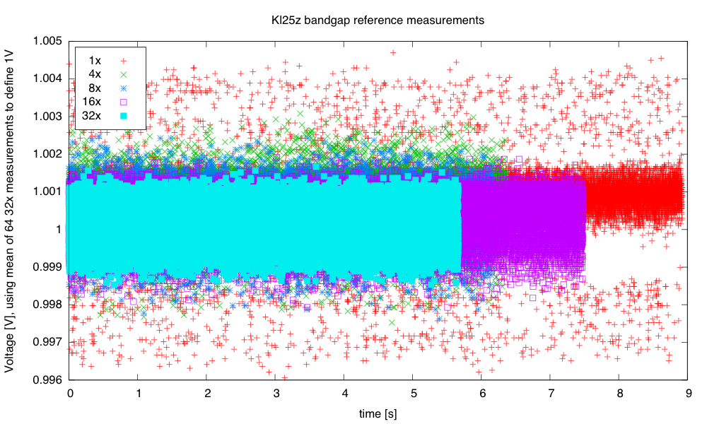
The unaveraged (1×) reading seems to be somewhat higher than any of the hardware-averaged ones.

I was curious about how the noise reduced on further averaging, and what the distribution was for each of the averaging levels. I plotted log histograms (using kernel-density estimates of the probability density function: gaussian_kde from the scipy python package) of the PteroDAQ-measured bandgap voltages.  The PteroDAQ is not really calibrated—the voltage reference is read 64 times with 32× averaging and the average of those 64 values taken to be 1V,  but the data sheet says that the  bandgap could be as much as 3% off (that’s better than the 10% error allowed on the ATMega chips).
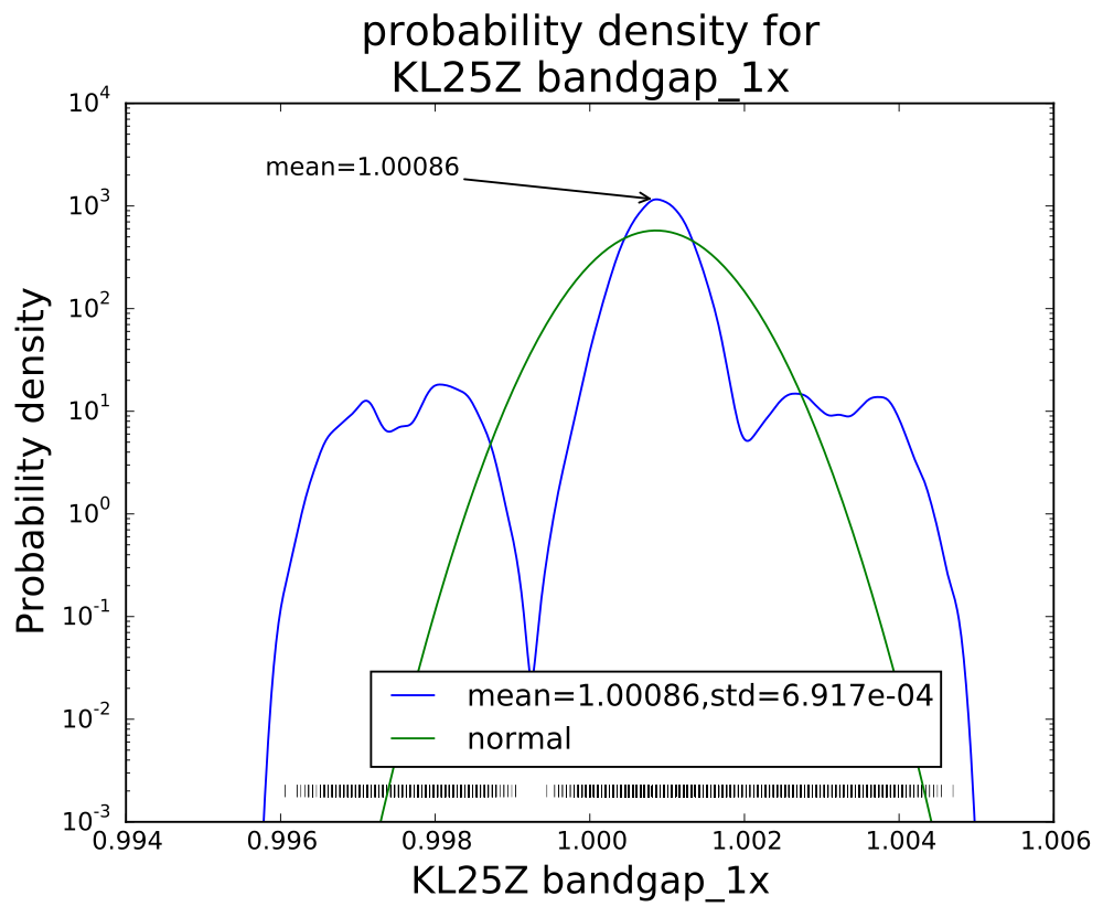
Without averaging, there is a curious pattern of missing values, which may be even more visible in the rug plot at the bottom than in the log histogram.
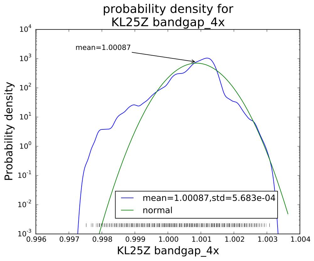
The smoothed log-histogram doesn’t show the clumping of values that is more visible in the rug plot.
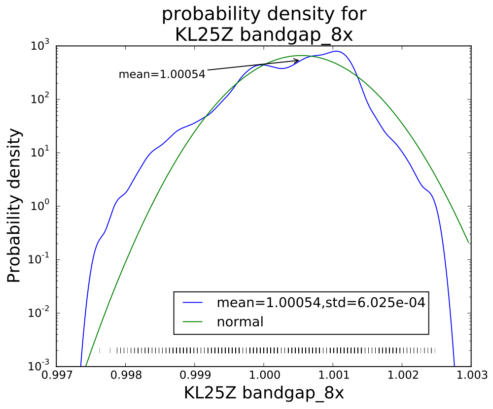
With eight averages, the distribution begins to look normal, but there is still clumping of values.
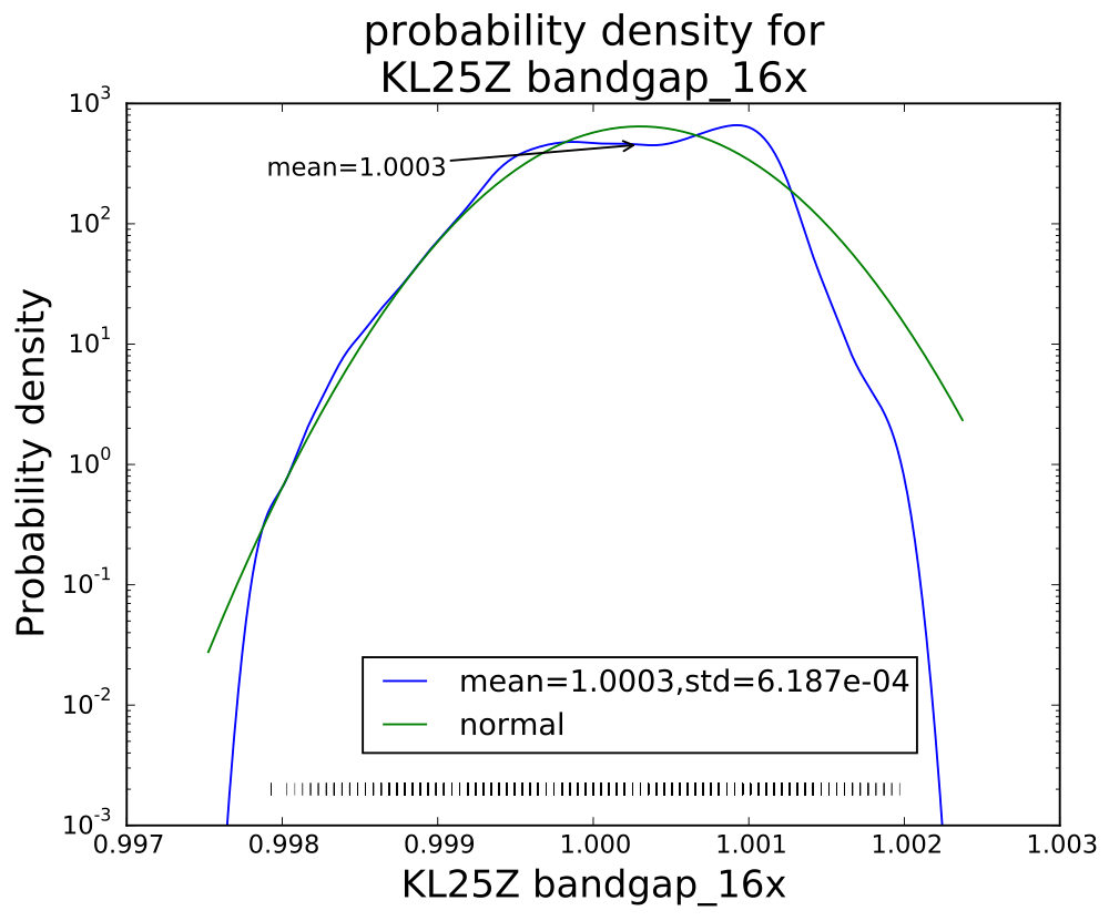
With 16 averages, things look pretty good, but mode is a bit offset from the mean still.
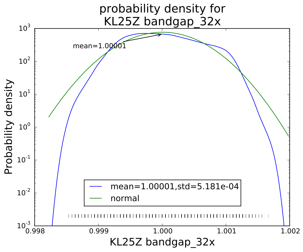
Averaging 32 values seems to have gotten an almost normal distribution.

Interestingly, though the range of values reduces with each successive averaging, the standard deviation does not drop as much as I would have expected (namely, that averaging 32 values would reduce the standard deviation to about 18% the standard deviation of a single value). Actually, I knew ahead of time that I wouldn’t see that much reduction, since the data sheet shows the effective number of bits only increasing by 0.75 bits from 4× t0 32×, while an 8-fold increase in independent reads would be an increase in effective number of bits of 1.5 bits.  The problem, of course, is that the hardware averaging is of reads one right after another, in which the noise is pretty highly correlated.

I think that the sweet spot for averaging is the 4× level—almost as clean as 32×, but 8 times faster.  More averaging improves the shape of the distribution a little, but doesn’t reduce the standard deviation by very much.  Of course, if one has a low-frequency signal with high-frequency noise, then heavier averaging might be worthwhile, but it would probably be better to sample faster with the 4× hardware averaging, and use a digital filter to remove the higher frequencies.

The weird distribution of values for the single read is not a property of the bandgap reference, but of the converter.  I made a voltage divider with a couple of resistors to get a voltage that was a fixed ratio of the supply voltage (so should give a constant reading), and saw a similar weird distribution of values:
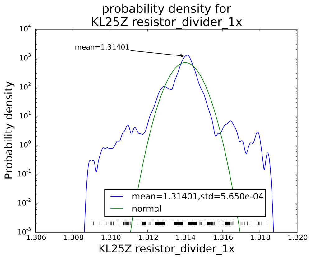
The distribution of single reads is far from a normal noise distribution, with fat tails on the distribution and clumping of values.


With 32× sampling, the mean is 1.31556 and the standard deviation 5.038E-04, with an excellent fit to a Gaussian distribution.


Filed under: Circuits course, Data acquisition Tagged: Arduino, histograms, KL25Z, noise, PteroDAQ, sampling frequency

PWM heater and fan continued

Yesterday I gave myself the following to-do list:

  • Check the VDS voltage at 4A on the nFET. Is the on-resistance still much too high?

    Yes, with the 1.8Ω resistor I get 110mV across the FET with 8.372V across the resistor, so at 4.65A I’m seeing an on-resistance of 24mΩ, still much higher than the 10mΩ I was expecting, but closer than I was getting yesterday at 1A. The voltage across the nFET does go up as the nFET warms up, but the nFET does not get too hot (up to around 45°C).

  • Try adding a 1kΩ gate resistance to slow down the transitions on the PWM, to see if that reduces the inductive spikes and the noise-coupling through the 9V power supply.

    Slowing the transitions definitely reduced the spikes, from about 13V to about 1V.  The bypass capacitors absorbed the highest-frequency spikes, and the 470µF polymer electrolytic capacitor seems to be enough—the 10µF ceramic doesn’t seem to add any extra suppression.  At about 94% duty cycle the noise on the power supply is about the following:

    gate resistor bypass capacitor peak-to-peak noise
     0Ω  none  20V
     1kΩ  none  3V
     0Ω  10µF  2.5V
     1kΩ  10µF  2.5V
     0Ω  470µF  1V
     1kΩ  470µF  0.3V

    The slew rate for the drain voltage with the 1kΩ gate resistor is about +7V/µs and -5V/µs.

  • Write a simple control loop for the fan speed, so that the fan speed can be held constant even when the power-supply voltage changes.  This may be an opportunity to try the P/PI/PID tuning, since the control loop should be fairly fast.

    I wrote a simple PID controller with the control variable being the fan PWM and the measured variable being the time per pulse (in µsec).  I tried tuning the controller by adjusting the proportional gain until the control loop barely oscillated, then cutting the gain to 0.45 of that and setting the integration time to about period of the oscillation (very loosely estimated).  I then tweaked the parameters until it seemed to give good control without oscillation over the full range of fan speeds.I tried the differential control, but the noisiness of the speed measurement (which I was not filtering at all) makes the derivative far too touchy, even with tiny amounts of differential control, so I used a simple PI controller instead.  I don’t think that the optimal parameters are the same at the high speed and low speed for the fan, but it was not difficult to find parameters that worked fairly well across the range.  One thing that help was not accumulating integral error when the PWM signal was pinned at the lowest or highest values.

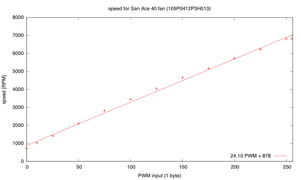
    The speed is almost linear with the PWM input, so I would probably get better control if I used speed (the reciprocal of the pulse duration) as the measured value in the controller.

    The fan speed is nearly linear with PWM, which is ideal for proportional control, but I had foolishly used the pulse duration as my measured value to control.

    I rewrote the controller as a simple PI controller, using 16*RPM as my measured variable, so that I could have an integer setpoint with sufficient resolution. I’m still using floating-point in the controller for simplicity of coding but I plan to switch to fixed-point soon. This controller was fairly easy to tune—I made the Kplarge enough that system oscillated, and counted how many samples were in the period, then set the integration time to about the period. I then reduced Kp until the oscillations went away. I ended up with Kp = 0.01 PWM/16RPM and TI= 1/0.15 samples (with a sampling rate of 30ms, so TI=0.2s).

    One thing that helped was to make a guess at the target PWM setting when the setpoint was changed (using d RPM/ d PWM =24 and the current PWM setting and RPM value), then setting the cumulative error to what it would be in steady state at that PWM. I then set the PWM to five times as far from current PWM as the target PWM to make the transition as fast as possible without increasing overshoot, making sure to clip to the legal 0..255 range.

  • Write a simple control loop for controlling the temperature at the thermistor, by adjusting the PWM for the resistor.  This might get messy, as the fan speed probably affects the rate of transfer from the resistor to the thermistor (the thermistor is in the air stream blown over the resistor, not touching the resistor).

    When I started working on this, my power supply failed. I’m afraid it might have shorted when I was rewiring things (though I never saw evidence for a short). I’ll leave it overnight (in case there is a resettable poly fuse) and check it in the morning. If there is still no power, I’ll open the case and see if there is a replaceable fuse inside. I’m afraid that this may have a soldered-in non-resettable fuse, which would be a terrible design—setting me back a couple of weeks as I either order a replacement fuse or a replacement power supply.

  • Put the whole thing into a styrofoam box, to see whether extra venting is needed to allow things to cool down, and to see how tightly temperature can be controlled.
  • Design and build baffling for the fan to get better airflow in the box.
  • Figure out how to get students to come up with workable designs, when they are starting from knowing nothing. I don’t want to give them my designs, but I want to help them find doable subproblems.  Some of the subproblems they come up with may be well beyond the skills that they can pick up in the time frame of the course.

Filed under: freshman design seminar Tagged: Arduino, fan, incubator, KL25Z, power resistor, PWM, tachometer, Teensy, thermistor

PWM heater and fan

Now that I have a power resistor and heatsink, and have verified that my power supply is capable of delivering 50W, I can try making a thermal control system for an incubator box as I hope to get the freshman design class to do.

Before building a complete control system and tuning a proportional, PI, or PID controller, I decided to check each of the components:

  • 1.8Ω resistor and heatsink (already characterized in still air in the previous post). Initially I was going to use the 8.2Ω resistor, but it heated so slowly once bolted to the heatsink that I wasn’t sure that students would have the patience to wait for it—they might conclude that things weren’t working.
  • NTD4858N-35G nFET for PWM control of the heater.
  • fan.  I bought a SanAce 40 109P0412P3H013 fan with PWM control and tachometer feedback, and I wanted to be sure that I could control the fan speed and read the tachometer.
  • thermistor. I had some NTCLE100E3103JB0 thermistors around that I had never used.  They’re not ideal for measuring temperature of resistors (they only go up to 125°C), but they should be find for measuring air temperature around 35°C, which is what the incubator will mainly be used at.
  • Arduino board (actually a SparkFun RedBoard, which is plug-compatible with the Uno R3, but has has a more reliable USB interface and is slightly cheaper.

I started out hooking up the nFET and the 1.8Ω resistor and making sure that the nFET did not get too hot.  It seems to be ok.  When I was using the 8.2Ω resistor, I measured the voltage drop across the resistor and the across the nFET, getting a 57.6mV drop from drain to source, with a current of about 9.024V/8.21ohm = 1.099A.  That’s about a 52mΩ on-resistance, and I was expecting more like 7mΩ–10mΩ.  My gate voltage was around 5V (bigger than the 4.5V of the data sheet), which should have given me lower on-resistance.  The only things I can think of are that I had more wiring resistance than I realized (quite likely, but not likely enough to add over 40mΩ), and that I was measuring around 1A, not around 10A, so perhaps there is a small-voltage effect that I don’t know about.

I should probably test the voltage drop again with 1.8Ω resistor, and see whether the on-resistance is still so high.  Better probe placement may get me more accurate voltage measurements also.

The fan runs fine at 9.212V at about 6850 RPM.  Setting the PWM input line of the fan to 0 drops the speed to about 710RPM, and setting the PWM duty cycle to a half sets the speed at about 4120RPM.  The fan is a bit noisy for such a tiny fan at the highest speed setting, but reasonably quiet at lower speeds.  I suspect that bolting the fan to a piece of masonite as a baffle would reduce the fan noise, as I think quite a bit of it was from vibration between the case of the fan and the metal plate it was sitting on.

The tachometer on the fan provides an open-collector output that I read with an interrupt input on the Arduino (pin 2, interrupt 0). I recorded the time between interrupts and converted it an RPM measurement.  The tachometer worked fine when I was just using the fan, or when the resistor was either completely off or completely on, but when I tried using PWM on the resistor, the tachometer readings became nonsense.

I looked at the tachometer signal with my oscilloscope and saw that the PWM transitions for the resistor resulted in huge spikes in the tachometer output that triggered extraneous interrupts.  I suspected noise coupled through the power supply. Adding a 10µF bypass capacitor to the 9V power supply to the fan reduced the problem considerably, and a 470µF aluminum polymer electrolytic cleaned up the power supply even more.  The 10µF alone was enough to eliminate the extraneous spikes in the middle.

I think that I should try adding some gate resistance to the nFET to slow down the rise and fall of the PWM signal a little, to reduce the inductive spikes and make the bypass capacitors more effective.

I noticed that I was still getting some readings that were half the duration that I was expecting.  These could have been caused by ringing at the other transition of the tachometer pulse, so I tried eliminating the ringing by adding some capacitance to the line and changing the pullup resistor.  These attempts were not very successful, so I decided that hysteresis was needed.  I put a Schmitt trigger between the open-collector output and the Arduino interrupt input, and the signal got a lot cleaner.  There were occasional double pulses at one edge, though, but I found that adding a 1nF to 10nF capacitor in parallel with the pullup resistor for the open collector output smoothed out the high frequency noise enough to get clean, single transitions out of the Schmitt trigger.

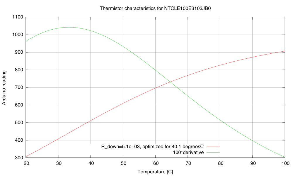
I hooked up the thermistor in a voltage divider with 5.1kΩ on the other leg (which maximizes the dV/dT sensitivity at 40.1°C). I used the parameters on the data sheet to plot a calibration curve for the thermistor:

Calibration and sensitivity curves for the thermistor, based on the data sheet and a 5.1kΩ pulldown resistor.

The maximum sensitivity of the thermistor circuit is around 33.3 degrees C (~10.4 Arduino LSB/°C).  That’s not a very high sensitivity, particularly given the noise of the ADC.  Note that maximizing the slope at 40.1 °C is not the same thing and having the maximum of the slope at 40.1°C.  If the maximum of the slope was at 40.1°C, the slope there would be less than it is in this plot.

My son wonders why I’m using the Arduino board for this project, rather than the FRDM-KL25Z board that I use for the circuits class or the Teensy 3.1 ARM development board. The ARM processors have more power, more memory, and much better analog-to-digital converters—and the KL25Z board is cheaper.  If I were doing this project for myself, I would certainly prefer the KL25Z board. But it is a little harder to get a beginner started on that board—just getting the first program onto the board is a pain if you don’t have a Windows machine (due to the broken bootloader the P&E Micro wrote).  There are instructions now for replacing the firmware from a Linux system, but I’ve not checked yet whether these instructions work from a Mac.  Even once you get working firmware onto the boards, the development environments are not beginner-friendly.  Well, that is certainly true of the MBED environment or bare-metal ARM environment for the KL25Z boards, but the Teensy 3.1 board supposedly can be programmed from a plugin for the Arduino IDE, which might be simple enough for beginners.  This is something for me to look into more.

Of course, one reason I’m using the Arduino Uno or Sparkfun RedBoard is that they are 5V processors, and most of the power nFETs I’ve looked at need 4.5V on the gate to turn on fully.  There are power nFETs now with lower gate voltages, but most of them are only available as surface-mount devices.  I don’t want to have to add an extra transistor or buffer chip as a level changer for the PWM circuit.

The problem is that these students will be brand new to programming, brand new to electronics, and brand new to engineering—and the course is only a 2-unit course, not a full 5-unit course, so the total time students are expected to spend on the course is only 60 hours. I want them to be able to design stuff quickly, without spending all their time learning to use tools or trying to find workarounds for limitations of the devices they are using. It already bothers me that they’ll probably need to use a Schmitt trigger to clean up the tachometer input, but at least hysteresis was a topic I was planning to cover! (The need for bypass capacitors bothers me less—they are so ubiquitous in electronics that I’ll have to cover them no matter what.)

It’s after midnight now, so I’m going to call it a day.  Here is my to-do list on this project:

  • Check the VDS voltage at 4A on the nFET. Is the on-resistance still much too high?
  • Try adding a 1kΩ gate resistance to slow down the transitions on the PWM, to see if that reduces the inductive spikes and the noise-coupling through the 9V power supply.
  • Write a simple control loop for the fan speed, so that the fan speed can be held constant even when the power-supply voltage changes.  This may be an opportunity to try the P/PI/PID tuning, since the control loop should be fairly fast.
  • Write a simple control loop for controlling the temperature at the thermistor, by adjusting the PWM for the resistor.  This might get messy, as the fan speed probably affects the rate of transfer from the resistor to the thermistor (the thermistor is in the air stream blown over the resistor, not touching the resistor).
  • Put the whole thing into a styrofoam box, to see whether extra venting is needed to allow things to cool down, and to see how tightly temperature can be controlled.
  • Design and build baffling for the fan to get better airflow in the box.
  • Figure out how to get students to come up with workable designs, when they are starting from knowing nothing. I don’t want to give them my designs, but I want to help them find doable subproblems.  Some of the subproblems they come up with may be well beyond the skills that they can pick up in the time frame of the course.


Filed under: freshman design seminar Tagged: Arduino, fan, incubator, KL25Z, power resistor, PWM, tachometer, Teensy, thermistor

Updates on some earlier lessons

In Still better I-V plot for Schottky diodes, I had some lessons learned at the end of the post:

  1. Higher-resolution ADCs do give smoother curves, with less digitization noise, but they aren’t a panacea for measurement problems. To get most of the resolution, I had to set the ADC to use long sample times and do a lot of averaging. I understand that Freescale Kinetis M series include 24-bit sigma-delta converters for higher precision at much lower speed (24 bits is 7 decimal digits), as well as the high-speed 16-bit successive-approximation converters. Unfortunately, they don’t have a low-cost development board for this series.
  2. Stay away from the bottom end of the ADC range on the KL25Z.  Scale single-ended inputs to have values at least 50, and differential inputs to have values at least 20.  There may be similar problems at the top end of the range, but I did not test for them.
    I wondered if the problem may be switching from the large value for the voltage across the diode to the small voltage across the shunt resistor that was the problem. I tried putting in a dummy read between the voltage and the current reads, but that didn’t help at all. At first I thought that the low-count readings were good with the large shunt resistors, but this is probably an illusion: errors in the current measurement for small currents aren’t visible on the plot, because the voltage across the diode is not changing, and so large horizontal errors in the plot are not visible there.
  3. Watch out for AC noise when trying to measure DC parameters.  If there are semiconductor junctions around, the noise may be rectified to produce an unwanted DC signal.
  4. The differential ADC settings have a range of ±VDDA, not ±VDDA/2. This means that the least-significant bit step size is twice as big for differential inputs as for single-ended inputs. For some reason the Freescale documentation never bothers to express what the differential range is.
  5. Serial USB connections are a bit flakey—the Arduino serial monitor missed a byte about every 200–300 lines.  I looked for anomalous points on the plot, then commented out the lines that produced them—they were almost all explainable by one character having been missed by the serial monitor; e.g., I commented out “662401069     86      19″ right after “660001069       865     17″,  because the last digit of the voltage (the second field) was missing.  The fields were a timestamp (in 24MHz ticks), voltage across the diode (in ADC units), and voltage across the shunt resistance (in ADC units).  [Actually, this was not a new lesson for me—I've had to do the same on almost all files collected from the Arduino serial monitor.  My son's data logger code is better at not losing data, but it is still worthwhile to check for anomalies.]
  6. The 3.3v supply from the Freedom board is much cleaner than the 5v USB supply that I get from the Arduino (unless I use an external power supply with the Arduino), but I can only take about 10mA from the 3.3v supply before it begins to droop.  If I want  more than that, I’d better provide my own power supply (or at least my own LDO regulator from the USB 5v supply).

I’d like to correct a few of those lessons in this post.

  1. A 24-bit sigma-delta converter is really only about 7 bits of accuracy—you are relying on oversampling with a single-bit comparator, then low-pass filtering.  Your resolution is a function of frequency, but the “24-bit” number is misleading—that’s how much precision they carry in the low-pass filter computations, and has little to do with the amount of information you can actually extract from the ADC. I think I was confusing sigma-delta converters (which are fast, cheap, and not very accurate) with dual-slope converters (which are slow and more accurate).
  2. no update.
  3. no update.
  4. no update.
  5. The UART communication from the Freescale KL25Z boards, using MBED’s code on OpenSDA chip to do the UART to USB conversion is much less reliable than the Arduino serial connections.  My son has been doing testing and has found that he can run the Arduino boards up to about 500k baud without losing characters (aside from a small number right after a reset), but the MBED-implemented UART communication on the KL25Z lost tens of character per second even at fairly low speeds (tested own to 62.5kbaud). We suspect a bug in their code in which they ignore the UART port for too long while dealing with the USB side.  (He’s not the first to notice that the MBED serial communication is broken on the KL25Z boards.) Using the MBED USB stack natively on the KL25 chip (not the SDA port), he had no noticeable character losses, so the problem is not on the host computer or the software he was testing with, but on the MBED implementation of the USB serial connection on the OpenSDA chip.
    This bug in MBED’s serial implementation has raised the complexity of the port of the data acquisition system to the KL25Z enormously, as he’ll have to implement a USB stack (or enough of one to do USB serial) on the KL25, rather than using the buggy one on the OpenSDA chip.  The MBED USB stack (written in C++) is not compatible with the bare metal ARM platform he’s been using for the port (which only seems to support C).  He’s gotten the USB code to compile and link, but is having trouble getting it to run—we suspect that some part of the C++ memory management has not been initialized properly.
    We have not checked whether the PEMicro OpenSDA software works for serial communication—since it doesn’t work for downloading software from the Mac, we can’t use it anyway.
  6. As I reported in Diode-connected nFET characterisitics, the 3.3V LDO on the KL25Z boards is actually pretty good: it can be modeled as 3.32V source with a 55mΩ series resistor. I got a steeper voltage drop above 500mA, but that was from overloading the USB 5v supply that was powering the board, not from problems with the LDO.
    I’ve not yet tried powering the board with a beefier power supply on the P5-9V_VIN pin. I suspect that it will be able to handle up to 1.5A without problems (maintaining the 55mΩ impedance).

Filed under: Circuits course Tagged: Arduino, KL25Z, MBED