Yesterday I gave myself the following to-do list:
- Check the VDS voltage at 4A on the nFET. Is the on-resistance still much too high?
Yes, with the 1.8Ω resistor I get 110mV across the FET with 8.372V across the resistor, so at 4.65A I’m seeing an on-resistance of 24mΩ, still much higher than the 10mΩ I was expecting, but closer than I was getting yesterday at 1A. The voltage across the nFET does go up as the nFET warms up, but the nFET does not get too hot (up to around 45°C).
- Try adding a 1kΩ gate resistance to slow down the transitions on the PWM, to see if that reduces the inductive spikes and the noise-coupling through the 9V power supply.
Slowing the transitions definitely reduced the spikes, from about 13V to about 1V. The bypass capacitors absorbed the highest-frequency spikes, and the 470µF polymer electrolytic capacitor seems to be enough—the 10µF ceramic doesn’t seem to add any extra suppression. At about 94% duty cycle the noise on the power supply is about the following:
| gate resistor |
bypass capacitor |
peak-to-peak noise |
| 0Ω |
none |
20V |
| 1kΩ |
none |
3V |
| 0Ω |
10µF |
2.5V |
| 1kΩ |
10µF |
2.5V |
| 0Ω |
470µF |
1V |
| 1kΩ |
470µF |
0.3V |
The slew rate for the drain voltage with the 1kΩ gate resistor is about +7V/µs and -5V/µs.
- Write a simple control loop for the fan speed, so that the fan speed can be held constant even when the power-supply voltage changes. This may be an opportunity to try the P/PI/PID tuning, since the control loop should be fairly fast.
I wrote a simple PID controller with the control variable being the fan PWM and the measured variable being the time per pulse (in µsec). I tried tuning the controller by adjusting the proportional gain until the control loop barely oscillated, then cutting the gain to 0.45 of that and setting the integration time to about period of the oscillation (very loosely estimated). I then tweaked the parameters until it seemed to give good control without oscillation over the full range of fan speeds.I tried the differential control, but the noisiness of the speed measurement (which I was not filtering at all) makes the derivative far too touchy, even with tiny amounts of differential control, so I used a simple PI controller instead. I don’t think that the optimal parameters are the same at the high speed and low speed for the fan, but it was not difficult to find parameters that worked fairly well across the range. One thing that help was not accumulating integral error when the PWM signal was pinned at the lowest or highest values.
The speed is almost linear with the PWM input, so I would probably get better control if I used speed (the reciprocal of the pulse duration) as the measured value in the controller.
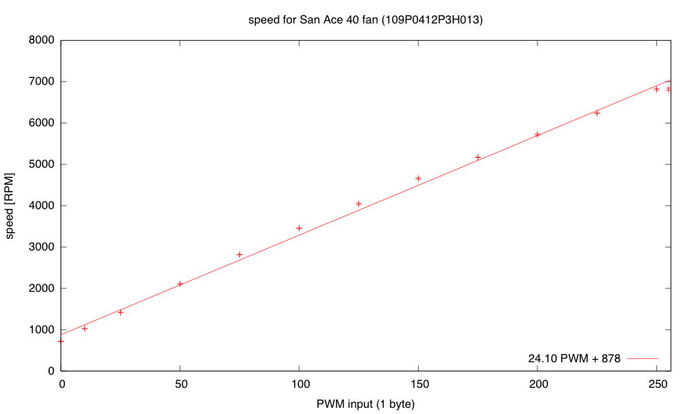
The fan speed is nearly linear with PWM, which is ideal for proportional control, but I had foolishly used the pulse duration as my measured value to control.
I rewrote the controller as a simple PI controller, using 16*RPM as my measured variable, so that I could have an integer setpoint with sufficient resolution. I’m still using floating-point in the controller for simplicity of coding but I plan to switch to fixed-point soon. This controller was fairly easy to tune—I made the Kplarge enough that system oscillated, and counted how many samples were in the period, then set the integration time to about the period. I then reduced Kp until the oscillations went away. I ended up with Kp = 0.01 PWM/16RPM and TI= 1/0.15 samples (with a sampling rate of 30ms, so TI=0.2s).
One thing that helped was to make a guess at the target PWM setting when the setpoint was changed (using d RPM/ d PWM =24 and the current PWM setting and RPM value), then setting the cumulative error to what it would be in steady state at that PWM. I then set the PWM to five times as far from current PWM as the target PWM to make the transition as fast as possible without increasing overshoot, making sure to clip to the legal 0..255 range.
- Write a simple control loop for controlling the temperature at the thermistor, by adjusting the PWM for the resistor. This might get messy, as the fan speed probably affects the rate of transfer from the resistor to the thermistor (the thermistor is in the air stream blown over the resistor, not touching the resistor).
When I started working on this, my power supply failed. I’m afraid it might have shorted when I was rewiring things (though I never saw evidence for a short). I’ll leave it overnight (in case there is a resettable poly fuse) and check it in the morning. If there is still no power, I’ll open the case and see if there is a replaceable fuse inside. I’m afraid that this may have a soldered-in non-resettable fuse, which would be a terrible design—setting me back a couple of weeks as I either order a replacement fuse or a replacement power supply.
- Put the whole thing into a styrofoam box, to see whether extra venting is needed to allow things to cool down, and to see how tightly temperature can be controlled.
- Design and build baffling for the fan to get better airflow in the box.
- Figure out how to get students to come up with workable designs, when they are starting from knowing nothing. I don’t want to give them my designs, but I want to help them find doable subproblems. Some of the subproblems they come up with may be well beyond the skills that they can pick up in the time frame of the course.
Filed under:
freshman design seminar Tagged:
Arduino,
fan,
incubator,
KL25Z,
power resistor,
PWM,
tachometer,
Teensy,
thermistor 


[original story: Gas station without pumps]
Yesterday I gave myself the following to-do list:
- Check the VDS voltage at 4A on the nFET. Is the on-resistance still much too high?
Yes, with the 1.8Ω resistor I get 110mV across the FET with 8.372V across the resistor, so at 4.65A I’m seeing an on-resistance of 24mΩ, still much higher than the 10mΩ I was expecting, but closer than I was getting yesterday at 1A. The voltage across the nFET does go up as the nFET warms up, but the nFET does not get too hot (up to around 45°C).
- Try adding a 1kΩ gate resistance to slow down the transitions on the PWM, to see if that reduces the inductive spikes and the noise-coupling through the 9V power supply.
Slowing the transitions definitely reduced the spikes, from about 13V to about 1V. The bypass capacitors absorbed the highest-frequency spikes, and the 470µF polymer electrolytic capacitor seems to be enough—the 10µF ceramic doesn’t seem to add any extra suppression. At about 94% duty cycle the noise on the power supply is about the following:
| gate resistor |
bypass capacitor |
peak-to-peak noise |
| 0Ω |
none |
20V |
| 1kΩ |
none |
3V |
| 0Ω |
10µF |
2.5V |
| 1kΩ |
10µF |
2.5V |
| 0Ω |
470µF |
1V |
| 1kΩ |
470µF |
0.3V |
The slew rate for the drain voltage with the 1kΩ gate resistor is about +7V/µs and -5V/µs.
- Write a simple control loop for the fan speed, so that the fan speed can be held constant even when the power-supply voltage changes. This may be an opportunity to try the P/PI/PID tuning, since the control loop should be fairly fast.
I wrote a simple PID controller with the control variable being the fan PWM and the measured variable being the time per pulse (in µsec). I tried tuning the controller by adjusting the proportional gain until the control loop barely oscillated, then cutting the gain to 0.45 of that and setting the integration time to about period of the oscillation (very loosely estimated). I then tweaked the parameters until it seemed to give good control without oscillation over the full range of fan speeds.I tried the differential control, but the noisiness of the speed measurement (which I was not filtering at all) makes the derivative far too touchy, even with tiny amounts of differential control, so I used a simple PI controller instead. I don’t think that the optimal parameters are the same at the high speed and low speed for the fan, but it was not difficult to find parameters that worked fairly well across the range. One thing that help was not accumulating integral error when the PWM signal was pinned at the lowest or highest values.
The speed is almost linear with the PWM input, so I would probably get better control if I used speed (the reciprocal of the pulse duration) as the measured value in the controller.

The fan speed is nearly linear with PWM, which is ideal for proportional control, but I had foolishly used the pulse duration as my measured value to control.
I rewrote the controller as a simple PI controller, using 16*RPM as my measured variable, so that I could have an integer setpoint with sufficient resolution. I’m still using floating-point in the controller for simplicity of coding but I plan to switch to fixed-point soon. This controller was fairly easy to tune—I made the Kplarge enough that system oscillated, and counted how many samples were in the period, then set the integration time to about the period. I then reduced Kp until the oscillations went away. I ended up with Kp = 0.01 PWM/16RPM and TI= 1/0.15 samples (with a sampling rate of 30ms, so TI=0.2s).
One thing that helped was to make a guess at the target PWM setting when the setpoint was changed (using d RPM/ d PWM =24 and the current PWM setting and RPM value), then setting the cumulative error to what it would be in steady state at that PWM. I then set the PWM to five times as far from current PWM as the target PWM to make the transition as fast as possible without increasing overshoot, making sure to clip to the legal 0..255 range.
- Write a simple control loop for controlling the temperature at the thermistor, by adjusting the PWM for the resistor. This might get messy, as the fan speed probably affects the rate of transfer from the resistor to the thermistor (the thermistor is in the air stream blown over the resistor, not touching the resistor).
When I started working on this, my power supply failed. I’m afraid it might have shorted when I was rewiring things (though I never saw evidence for a short). I’ll leave it overnight (in case there is a resettable poly fuse) and check it in the morning. If there is still no power, I’ll open the case and see if there is a replaceable fuse inside. I’m afraid that this may have a soldered-in non-resettable fuse, which would be a terrible design—setting me back a couple of weeks as I either order a replacement fuse or a replacement power supply.
Correction: the power supply was fine—I’d managed to blow a circuit breaker for the room. I’m not sure how I did that, but resetting the circuit breaker fixed the problem. I now have a temperature control sort of working—I still have to tune the control loop, but I was able to get the thermistor to about 30°C (400 as the Arduino reading) and hold it to within about 0.3°C. There was a pretty substantial overshoot at the beginning, which I’ll have to look into controlling—the temperature controller may need to be critically damped. Now it really is time for me to get some sleep.
- Put the whole thing into a styrofoam box, to see whether extra venting is needed to allow things to cool down, and to see how tightly temperature can be controlled.
- Design and build baffling for the fan to get better airflow in the box.
- Figure out how to get students to come up with workable designs, when they are starting from knowing nothing. I don’t want to give them my designs, but I want to help them find doable subproblems. Some of the subproblems they come up with may be well beyond the skills that they can pick up in the time frame of the course.
Filed under:
freshman design seminar Tagged:
Arduino,
fan,
incubator,
power resistor,
PWM,
tachometer,
thermistor 
[original story: Gas station without pumps]


