Posts with «diy» label

Behold The Mega-Wheelie, a Huge One-Wheeled Electric Skateboard

DIY electric personal vehicles are a field where even hobbyists can meaningfully innovate, and that’s demonstrated by the Mega-Wheelie, a self-balancing one-wheeled skateboard constructed as an experiment in traversing off-road conditions.

[John Dingley] and [Nick Thatcher] have been building and testing self-balancing electric vehicles since 2008, with a beach being a common testing ground. They suspected that a larger wheel was the key to working better on rough ground and dry sand and tested this idea by creating a skateboard with a single wheel. A very big, very wide wheel, in fact.

The Mega-Wheelie houses a 24V LiFePO4 battery pack, 450 W gearmotor with chain and sprocket drive, SyRen motor controller from Dimension Engineering, Arduino microcontroller, and an inertial measurement unit to enable the self-balancing function. Steering is done by leaning, and the handheld controller is just a dead man’s switch that disables the vehicle if the person piloting it lets go.

Design-wise, a device like this has a few challenging constraints. A big wheel is essential for performance but takes up space that could otherwise be used for things like batteries. Also, the platform upon which the pilot stands needs to be as low to the ground as possible for maximum stability. Otherwise, it’s too easy to fall sideways. On the other hand, one must balance this against the need for sufficient ground clearance.

Beaches are rarely covered in perfectly smooth and firm sand, making them a good test area.

In the end, how well did it work? Well enough to warrant a future version, says [John]. We can’t wait to see what that looks like, considering their past 3000 W unicycle’s only limitation was “personal courage” and featured a slick mechanism that shifted the pilot’s weight subtly to aid steering. A video of the Mega-Wheelie (and a more recent unicycle design) is embedded just below the page break.

And just for reference, here is some of [John]’s previous work on a self-balancing unicycle design.

DIY Arduino Due TEA5767 FM Radio

Older hackers will remember that a crystal set radio receiver was often one of the first projects attempted.  Times have changed, but there’s still something magical about gathering invisible signals from the air and listening to the radio on a homemade receiver. [mircemk] has brought the idea right up to date by building an FM radio with an OLED display, controlled with a rotary encoder.

The design is fairly straightforward, based as it is on another project that [mircemk] found on a Chinese site, but the build looks very slick and would take pride of place on any hacker’s workbench. An Arduino Due forms the heart of the project, controlling a TEA5767 module, an SH1106 128×64 pixel OLED display and a rotary encoder. The sound signal is passed through an LM4811 headphone amplifier for private listening, and a PAM8403 Class D audio amplifier for the built-in loudspeaker. The enclosure is made from PVC panels, and accented with colored adhesive tape for style.

It’s easier than ever before to quickly put together projects like this by connecting pre-built modules and downloading code from the Internet, but that doesn’t mean it’s not a worthwhile way to improve your skills and make some useful devices like this one. There are so many resources available to us these days and standing on the shoulders of giants has always been a great way to see farther.

We’ve shown some other radio projects using Arduinos and the TEA5767 IC in the past, such as this one on a tidy custom PCB, and this one built into an old radio case.

Hack a Day 09 Oct 06:00

FM Radio from Scratch using an Arduino

Building radio receivers from scratch is still a popular project since it can be done largely with off-the-shelf discrete components and a wire long enough for the bands that the radio will receive. That’s good enough for AM radio, anyway, but you’ll need to try this DIY FM receiver if you want to listen to something more culturally relevant.

Receiving frequency-modulated radio waves is typically more difficult than their amplitude-modulated cousins because the circuitry necessary to demodulate an FM signal needs a frequency-to-voltage conversion that isn’t necessary with AM. For this build, [hesam.moshiri] uses a TEA5767 FM chip because of its ability to communicate over I2C. He also integrated a 3W amplifier into this build, and everything is controlled by an Arduino including a small LCD screen which displays the current tuned frequency. With the addition of a small 5V power supply, it’s a tidy and compact build as well.

While the FM receiver in this project wasn’t built from scratch like some AM receivers we’ve seen, it’s still an interesting build because of the small size, I2C capability, and also because all of the circuit schematics are available for all of the components in the build. For those reasons, it could be a great gateway project into more complex FM builds.

Hack a Day 05 Dec 00:00

Spherical Quadruped Arduino Robot

[Greg06] started learning electronics the same way most of us did: buy a few kits, read a few tutorials, and try your hardest to put a few things together. Sound familiar? After a while, you noticed your skills started increasing, and your comfort level with different projects improved as well. Eventually, you try your hand at making your own custom projects and publishing your own tutorials.

Few are lucky to have a first-project as elaborate as [Greg06’s] quadruped robot. We don’t know about you, but for some of us, we were satisfied with blinking two LEDs instead of just one.

[Greg06’s] robot has a quadruped based, housed within a 3D printed spherical body. The legs are retractable and are actuated by tiny servo motors inside the body. [Greg06] even included an ultrasonic distance sensor for the obstacle avoidance mechanism. Honestly, if it weren’t for the ultrasonic distance sensor protruding from the spherical body, you might think that the entire robot was just a little Wiffle ball. This reminds us of another design we’ve seen before.

If that weren’t enough, the spherical head can rotate, widening the range of the ultrasonic distance sensor and obstacle avoidance mechanism. This is accomplished by attaching another servo motor to the head.

Pretty neat design if you ask us. Definitely one of the coolest quadrupeds we’ve seen.

Daisy is a tiny $29 computer for building custom musical instruments

Coding your own musical instruments just got a lot more convenient. Music tech company Electrosmith has launched the Daisy, an open source microcomputer packed with everything you need to code your own pedals, synth, modules and instruments -- and it's the size of a stick of gum.

Source: Kickstarter

You can make your own rotary cellphone

As convenient as modern cellphones are, there's a certain charm to spinning an old-fashioned rotary dial to make a call -- and now, there's a cellphone that caters to that nostalgia. Brookhaven National Lab engineer Justine Haupt has developed a rotary cellphone that's not only functional, but available to make with the help of a $240 do-it-yourself kit. It's effectively a throwback to the days when phones were for calling and nothing else, plus a few present-day creature comforts.

Source: Justine Haupt, Sky's Edge

You can make your own rotary cellphone

As convenient as modern cellphones are, there's a certain charm to spinning an old-fashioned rotary dial to make a call -- and now, there's a cellphone that caters to that nostalgia. Brookhaven National Lab engineer Justine Haupt has developed a rotary cellphone that's not only functional, but available to make with the help of a $240 do-it-yourself kit. It's effectively a throwback to the days when phones were for calling and nothing else, plus a few present-day creature comforts.

Create your own Arduino Library

Project Description

In this short tutorial I will show you how to create your own Arduino Library. Making your own library seems daunting at first, but I will show you that it is not much harder than writing your own script/sketch. I would advise that you comment you code clearly, because when you come back to it in 5 years time, it will help to navigate you through your code at this time in history. Here we go, let's go through the process of creating a very simple Arduino library.

Parts Required

  • Arduino UNO or compatible board

Project Steps

Before we begin, there are a few questions you must ask yourself:

  1. What will the library be called ?
  2. What will the library do ?
  3. What are you trying to simplify?

For our library, these are the answers to the questions above:

  1. BlinkMe
  2. It will blink an LED attached to one of the digital pins
  3. The aim is to reduce the blink commands to a single line

Create a Folder

Create a folder on your computer which will be used to house all of the files in this project. Name the folder the same name as the library. In this case we will name it "BlinkMe". Make sure you use consistent naming throughout the tutorial. Capital and lowercase letters do matter.

Create the files

Using any text based editor (eg. notepad++, PSPad, Notepad2 etc), you will need to create 3 blank files:

  • The C++ file (BlinkMe.cpp) : Library code containing all of the functions
  • The Header file (BlinkMe.h): Contains the library function declarations
  • keywords.txt : Used for syntax highlighting within the Arduino IDE

I will tell you what you need to write inside each of these files, but make sure you have the blank BlinkMe.cpp, BlinkMe.h and keywords.txt files inside of the BlinkMe folder. Some people start by creating the header file first, but I personally like to start with the CPP file.
We will now look to populate the BlinkMe C++ file:

The C++ file (.cpp)

This file will contain all of the functions in your new library.
The first thing you will need to do is include the Arduino.h file. This will drag in all of the relevant Arduino code necessary for your library to function with an Arduino. And while we haven't yet created the header file (BlinkMe.h), we need to import that also. So the first two lines should be:

#include <Arduino.h>
 #include <BlinkMe.h>

The next section of code is the "constructor". This will be responsible for constructing the BlinkMe object. The BlinkMe object will allow you to call any of the public functions within the BlinkMe library. The constructor will allow us to define the default variables or constants.

BlinkMe::BlinkMe(){
    _dPin = 13;
 }

Sometimes we will want to blink an LED on a different pin. So we will create a function to set the pin that we would like use.

void setOUTPUT(int dPin){
    _dPin = dPin;
    pinMode(_dPin, OUTPUT);
 }

The only thing left is to create the useful part of the code. We will create a simple function that will blink the LED for a set duration. The function will have a parameter, which will be used to set the blink duration.

void blink(unsigned long delay_1){
    _delay_1 = delay_1;
    digitalWrite(_dPin, HIGH);
    delay(_delay_1);
    digitalWrite(_dPin, LOW);
    delay(_delay_1);
 }

Here is the complete "BlinkMe.cpp" file:

The Header file (.h)

The header file will be used to create the library function declarations. Open the "BlinkMe.h" file.
The first step is to check to make sure that the library is NOT already defined:

#ifndef BlinkMe_h

If it is not defined, then we must define the library:

#define BlinkMe_h

We then need to provide access to the standard Arduino types and constants

#include "Arduino.h"

And finally create the BlinkMe class:

//Create the class BlinkMe
class BlinkMe{
    public:
        BlinkMe();
        void setOUTPUT(int dPin);
        void blink(unsigned long delay_1);
    private:
        int _dPin;
        unsigned long _delay_1;
 };
#endif

Here is the complete header file:

keywords.txt (optional)

The keywords.txt file will contain the keywords for the library which will allow appropriate syntax highlighting. This file is optional, however it will highlight your classes or functions based on the keyword mapping.

  • LITERAL1: specifies constants (eg. HIGH, LOW,
  • KEYWORD1: specifies classes (eg. Serial)
  • KEYWORD2: specifies methods and functions (eg. analogRead, digitalWrite, delay)
  • KEYWORD3: specifies structures (eg. if, while, loop)
You need to make sure you use a single tab between the keyword and the "KEYWORD" mapping. In our example, BlinkMe is a class, so that would be a KEYWORD1. On the other hand, "blink" is a function, so that would be a KEYWORD2. So the keywords.txt file will contain the following text:

BlinkMe     KEYWORD1
setOUTPUT   KEYWORD2
blink       KEYWORD2

Example Sketch (optional)

It is often useful to include an sketch that provides an example of the library in use. It provides some context. If you plan to include the sketch in your library, then you must follow these simple rules:

  1. Create an "examples" folder.
  2. Create an example sketch, an place it within a folder of the same name as the sketch
  3. Place the sketch folder inside of the examples folder
You will end up with something like: examples/example_sketch/example_sketch.ino
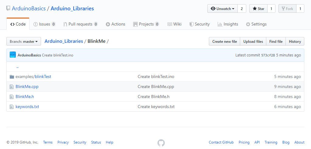
In our case it will be: examples/blinkTest/blinkTest.ino

Here is the example sketch for this library (Save as blinkTest.ino):
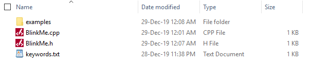

The library

Here is a picture of the library contents:

And now the only thing left is to zip up the library folder and import it into the Arduino IDE. Use whatever program you want to zip up the BlinkMe folder, and note the location of the zip file. You need to import the zip file into the Arduino IDE:

  • Arduino IDE > Sketch > Include Library > Add .ZIP Library...
  • Select the library zip file you just created, and select "Open".
  • You can now use your library in the Arduino IDE.
  • Test it by running your example sketch: File > Examples > BlinkMe > blinkTest

Download

You can download the entire library here:
BlinkMe Library

Conclusion

In this tutorial, I showed you how to create a simple Arduino library. If you would like so see another example, have a look at my ToggleTimer library, which is very useful when trying to blink an LED without using a delay.You don't have to limit yourself to LEDs, you can use it for other projects where delay gets in the way. ToggleTimer is a non-blocking timer that toggles between two states.


If you found this tutorial helpful, please consider supporting me by buying me a virtual coffee/beer.

$3.00 AUD only

Social Media

You can find me on various social networks:

Follow me on Twitter: ScottC @ArduinoBasics.
I can also be found on Instagram, Pinterest, and YouTube.
And if all else fails, I have a server on Discord.


ScottC 29 Dec 10:09
arduino  blink  diy  led  library  tutorial  

A Better Embroidery Machine, With 3D Printing and Common Parts

In concept, an everyday sewing machine could make embroidery a snap: the operator would move the fabric around in any direction they wish while the sewing machine would take care of slapping down stitches of colored thread to create designs and filled areas. In practice though, getting good results in this way is quite a bit more complex. To aid and automate this process, [sausagePaws] has been using CNC to take care of all the necessary motion control. The result is the DIY Embroidery Machine V2 which leverages 3D printed parts and common components such as an Arduino and stepper drivers for an economical DIY solution.

It’s not shown in the photo here, but we particularly like the 3D printed sockets that are screwed into the tabletop. These hold the sewing machine’s “feet”, and allow it to be treated like a modular component that can easily be removed and used normally when needed.

The system consists of a UI running on an Android tablet, communicating over Bluetooth to an Arduino. The Arduino controls the gantry which moves the hoop (a frame that holds a section of fabric taut while it is being embroidered), while the sewing machine lays down the stitches.

[sausagePaws]’s first version worked well, but this new design really takes advantage of 3D printing as well as the increased availability of cheap and effective CNC components. It’s still a work in progress that is a bit light on design details, but you can see it all in action in the video embedded below.