Posts with «neopixels» label

Electronic Connect Four Has No Pieces to Lose

Recreating classic games in software is a great way to get better at coding or learn to code in the first place. If you do it in hardware though, you’ll gain a lot more than coding skills. Just ask [Kelly] and [Jack] did, when they built this Arduino-based electronic Connect Four for a school project.

We love that their interpretation manages to simplify game play and make it more fun than the original version. All the players have to do is turn it on and start pushing the arcade buttons along the bottom to choose the column where they want to make a play. The LEDs animate from top to bottom to imitate the plastic disc dropping down through the board. If a win is detected — four in a row of the same color going any direction — the board fills up with the winning color and the game starts over.

The state machine doesn’t currently do anything about tie situations, so there’s a reset button hidden on the side. As [Kelly] and [Jack] explain in their walk-through video after the break, that is something they would like to address in the future, along with making it possible to choose whatever battle color you want. We think a reset animation that mimics the look of the discs spilling out the bottom would be cool, too.

If you’ve never implemented a game on hardware before, something like this might be a bit daunting. May we suggest a game of 4×4 Tic Tac Toe instead?

Mademoiselle Pinball Table Gets Rock ‘n Roll Makeover

Once upon a time, there was a music venue/artist collective/effects pedal company that helped redefine industry in Williamsburg, Brooklyn. That place was called Death By Audio. In 2014, it suffered a death by gentrification when Vice Media bought the building that DBA had worked so hard to transform. From the ashes rose the Death By Audio Arcade, which showcases DIY pinball cabinets made by indie artists.

Their most recent creation is called A Place To Bury Strangers (APTBS). It’s built on a 1959 Gottlieb Mademoiselle table and themed around a local noise/shoegaze band of the same name that was deeply connected to Death By Audio. According to [Mark Kleeb], this table is an homage to APTBS’s whiz-bang pinball-like performance style of total sensory overload. Hardly a sense is spared when playing this table, which features strobe lights, black lights, video and audio clips of APTBS, and a fog machine. Yeah.

[Mark] picked up this project from a friend, who had already cut some wires and started hacking on it. Nearly every bit of the table’s guts had to be upgraded with OEM parts or else replaced entirely. Now there’s a Teensy running the bumpers, and another Teensy on the switches. An Arduino drives the NeoPixel strips that light up the playfield, and a second Uno displays the score on those sweet VFD tubes. All four micros are tied together with Python and a Raspi 3.

If you’re anywhere near NYC, you can play the glow-in-the-dark ball yourself on July 15th at Le Poisson Rouge. If not, don’t flip—just nudge that break to see her in action. Did we mention there’s a strobe light? Consider yourself warned.

Want to get into DIY pinball on a smaller scale? Build yourself a sandbox and start playing.

Pi Time – A Fabric RGB Arduino Clock

Pi Time is a psychedelic clock made out of fabric and Neopixels, controlled by an Arduino UNO. The clock started out as a quilted Pi symbol. [Chris and Jessica] wanted to make something more around the Pi and added some RGB lights. At the same time, they wanted to make something useful, that’s when they decided to make a clock using Neopixels.

Neopixels, or WS2812Bs, are addressable RGB LEDs , which can be controlled individually by a microcontroller, in this case, an Arduino. The fabric was quilted with a spiral of numbers (3.1415926535…) and the actual reading of the time is not how you are used to. To read the clock you have to recall the visible color spectrum or the rainbow colors, from red to violet. The rainbow starts at the beginning of the symbol Pi in the center, so the hours will be either red, yellow, or orange, depending on how many digits are needed to tell the time. For example, when it is 5:09, the 5 is red, and the 9 is yellow. When it’s 5:10, the 5 is orange, the first minute (1) is teal, and the second (0) is violet. The pi symbol flashes every other second.

There are simpler and more complicated ways to perform the simple task of figuring out what time it is…

We are not sure if the digits are lighted up according to their first appearance in the Pi sequence or are just random as the video only shows the trippy LEDs, but the effect is pretty nice:


Filed under: Arduino Hacks, led hacks
Hack a Day 17 Apr 03:00

Bluetooth Speaker With Neopixel Visual Display!

Finding a product that is everything you want isn’t always possible. Making your own that checks off all those boxes can be. [Peter Clough] took the latter route and built a small Bluetooth speaker with an LED visualization display that he calls Magic Box.

A beefy 20W, 4Ohm speaker was screwed to the lid of a wooden box converted to the purpose. [Clough] cut a clear plastic sheet to the dimensions of the box, notching it 2cm from the edge to glue what would become the sound reactive neopixel strip into place — made possible by an electret microphone amplifier. There ended up being plenty of room inside the speaker box to cram an Arduino Pro Mini 3.3V, the RN-52 Bluetooth receiver, and the rest of the components, with an aux cable running out the base of the speaker. As a neat touch, neodymium magnets hold the lid closed.

We gotta say, a custom speaker with LED visualization makes for a tidy little package — aside from the satisfaction that comes from building it yourself.

Depending on your particular situation, you may even opt to design a speaker that attaches to a magnet implanted in your head.

[via /r/DIY]


Filed under: Arduino Hacks, hardware, led hacks, musical hacks

Ride an Arduino-powered longboard with speed-reactive LEDs

For a recent column in the Dutch newspaper de Volkskrant, Rolf Hut built a slick longboard with LED strips that respond to speed. If you think that sounds awesome, wait until you see it in action.

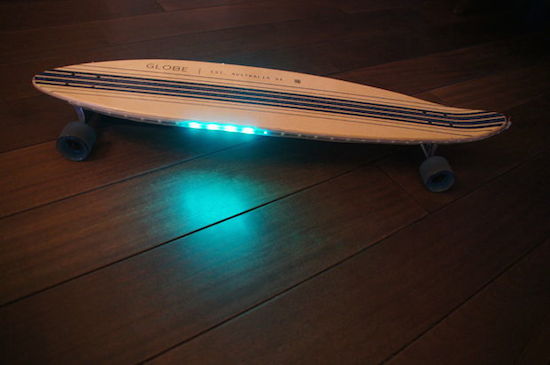
As the Maker explains, four magnets and a Hall effect sensor are used to measure the longboard’s speed so the Adafruit NeoPixels can react at the same pace. To achieve this, the magnets are glued to the inside of each wheel, while a Hall sensor counts the number of revolutions and sends that information over to one of two Arduino Micros. The first Arduino translates that into a speed, while the second Micro converts that speed into a signal for the LEDs. Everything is powered by a power bank.

Intrigued? Head over to the Hut’s project page, where you will find a detailed breakdown of his build along with its code.

A DIY digital Arduino clock designed for and by teachers

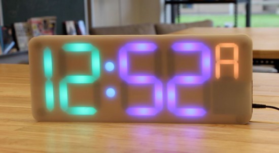
Project-based lessons are a great way to introduce students to the world of electronics. Clearly Jenna Debois agrees, as she has built a DIY classroom clock based on an Arduino Nano. What’s even cooler is that it’s optimized for teachers! 

The device is made using laser-cut wood pieces, NeoPixels, a real-time clock module, and packs plenty of customizable features like:

  • An additional digit that keeps track of the block or period- an especially useful feature for rotating block schedules
  • The ability to program holidays into the code to prevent the block from advancing on days when school is not in session
  • LED digits that fade from green to red as the end of the period or block approaches so that a single glance can convey the remaining class time
  • A countdown timer triggered 6 minutes before the period ends that flashes between the time and the remaining time- a useful feature for signaling cleanup time
  • Other light effects that can be triggered during lunch, free periods, after school, or other special occasions

Debois not only created a step-by-step guide, but also shared all the documentation on GitHub and a detailed video of the build process.

Arduino Pro Mini powers this Pac-Man festival totem

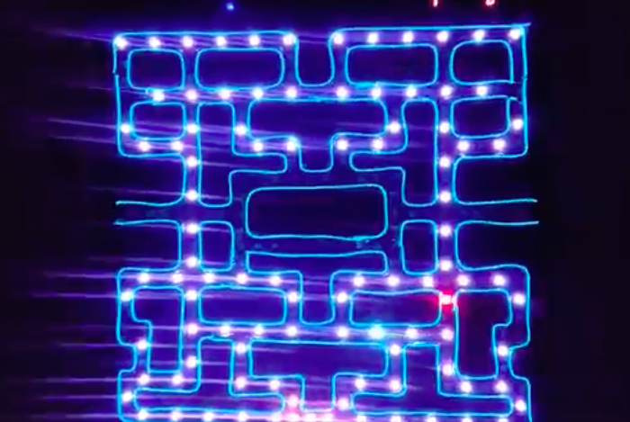
Electric Daisy Carnival Las Vegas is just days away, and YouTuber “Korberos” is ready. The Maker has created an LED Pac-Man totem using 967 lines of code, 256 NeoPixels wired in succession and laid out in a game-inspired map, and an Arduino Pro Mini.

The controller and game lights are powered by a 5V power bank with 10,000mAh of storage, while blue EL wire lights (for the “walls”) are powered by a 12V supply coming from eight AA batteries wired in serial. A MAC7219 7-segment display shows the current level and score.

According to Korberos, two libraries were used in the project: FastLED to control the LED strips and LedControl2 to handle the scoreboard.

Get the party started with these coke bottle lights

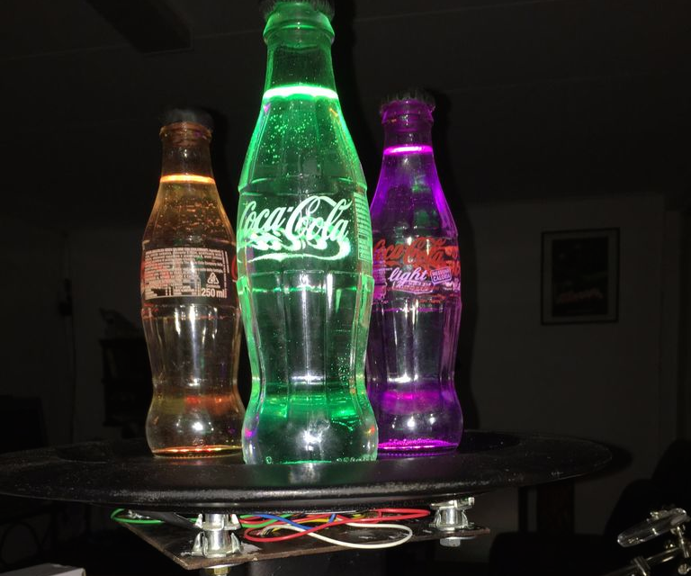
With school just about out for the summer, Brian Fitzgerald’s son was throwing a party to celebrate the end of exam week. Like any cool Maker dad would, he decided to build awesome lights made out of a few old soda bottles, the “gooey innards” of glow sticks, and some other supplies he had lying around the basement.

Fitzgerald used a wooden plate for the base and a playground post bracket for the mount, along with an Arduino Leonardo (though any Arduino would do) and three NeoPixel rings for the colorful effects.

Fill the Coke bottles with water. Alternatively, you can add a drop of milk to get a cloudy effect — it makes the liquid translucent and gives the impression of solid light, but you loose the little bubble and scratch effects that clear water highlights, which we thought was cooler. We put a black Sugru cap on the bottles to avoid a drunken accident involving water and electronics. And filled the countersunk bolt holes with Sugru to hide the bolt heads as well.

I attached the plastic Arduino casing with double-sided velcro to the base unit for easy removal. It’d look nicer if I’d put the whole unit inside the base, but as we’re planning to pull the board out and modify for music sensitivity, I opted for convenience over beauty. If anybody has any cool Arduino code that gets an Adafruit auto-gain mic and NeoPixels jamming via FFT, I’d love to see it. There are some great color organ projects out there, but I can’t seem to find this particular combo. So we may have to write it ourselves!

Plug the 9v wall wart into the Arduino and BOOM. You got yourself a classic party light that’s mesmerizing to look at, throws patterns on the ceiling that look like Hubble images of distant nebulae, a fine conversation piece, and a bunch of cast off junk transformed into a thing of beauty.

Intrigued? You can check out the entire project on Instructables, as well as see it in action below.


Arduino LED Light Box

Description

Long straight lines of LED luminescence is nice, but sometimes you may want to light up something that has an unusual shape, or is not so linear. This is where the 12mm diffused flat digital RGB LED Pixels can come into play. This cool strand of 25 RGB LED pixels fit nicely into 12mm pre-drilled holes of any material you like.

This tutorial is dedicated to making a LED Light Box. I wanted the box to be equally as interesting during the day as it was at night. If you decide you make your own, feel free to be as creative as you want !! However, if you lack artistic acumen, you may need to source a minion or two.


Arduino Libraries and IDE

Before you start to hook up any components, upload the following sketch to the Arduino microcontroller. I am assuming that you already have the Arduino IDE installed on your computer. If not, the IDE can be downloaded from here.

The FastLED library is useful for simplifying the code for programming the RGB LED pixels. The latest "FastLED library" can be downloaded from here. I used FastLED library version 3.0.3 in this project.

If you have a different LED strip or your RGB LED pixels have a different chipset, make sure to change the relevant lines of code to accomodate your hardware. I would suggest you try out a few of the FastLED library examples before using the code below, so that you become more familiar with the library, and will be better equipped to make the necessary changes.

If you have a single strand of 25 RGB LED pixels with the WS8201 chipset, then you will not have to make any modification below.


ARDUINO CODE:

Arduino Code Description

The code above will generate a randomised raindrop pattern on the Arduino LED Light box, however I have written code for a few more LED animations. These animations were written specifically for this light-box setup. In other words, once you have hooked everything up, you will be able to upload these other LED animations to the Arduino board without any further modification to the hardware/wiring, and yet experience a totally different light effect. You can find the code for the other animation effects by clicking on the links below:

  1. Breathing effect
  2. Ripple effect
  3. Clock effect
  4. Rotation effect
  5. Sweep effect
  6. Spiral effect
  7. Lightning effect
  8. Paparazzi in the Rain effect

Hooking it up:

Power requirements

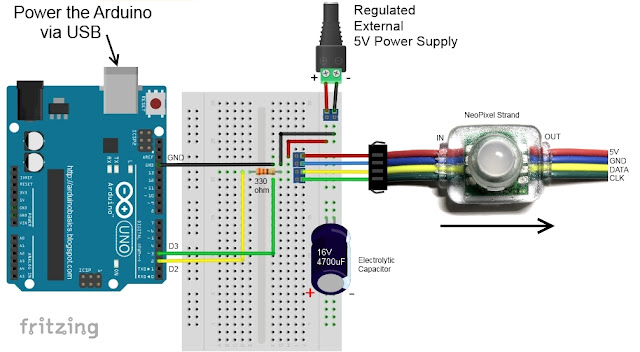
Each LED pixel can draw up to 60 milliamps at maximum brightness (white). ie. 20 mA for each colour (red, green and blue). Therefore you should not try to power the LED strand directly from the Arduino, because the strand will draw too much current and damage the microcontroller(and possibly your USB port too). The LED strand will therefore need to be powered by a separate power supply. The power supply must supply the correct voltage (5V DC) and must also be able to supply sufficient current (1.5A or greater per strand of 25 LEDs).

Excessive voltage will damage or destroy your LED pixel strand. The LEDs will only draw as much current as they need, however your power supply must provide at least 1.5A or greater for each strand. If you chain two strands together, you will need a 5V 3A power supply.

RGB LED pixel strand connection

There are 25 LED pixels per strand. Four of the wires at each end of the strand are terminated with a JST connector. The red wire is for power (VCC), blue wire for ground (GND), yellow wire is for Data, and green wire for Clock. A spare red wire (VCC) and a spare blue wire (GND) are attached to the ends of each strand for convenience, however, I did not use either. Please double check the colour of your wires... they may be different.

If you want to attach the LED strand to a breadboard, you can cut the JST connector off and use the LED pixel strand wires. Alternatively, if you would prefer to preserve the JST connector, you can simply insert jumper wires (or some male header pins) into the JST connector, and then plug them into the breadboard as required.

Each LED pixel is individually controllable using two pins on your Arduino. The strand is directional. i.e. There is an INPUT side and an OUTPUT side. The strand should be connected such that wires from the microcontroller are attached to the INPUT side of the first LED pixel. The arrows on each LED show the direction of data flow from INPUT to OUTPUT. The arrow on the first LED pixel should be pointing towards the second LED pixel, NOT towards the breadboard.

Other considerations

As a precaution, you should use a large capacitor across the + and - terminals of the power supply to prevent the initial onrush of current from damaging the RGB LED pixels. I used a 4700uF 16V Electrolytic capacitor for this purpose. According to Adafruit, a 1000uF 6.3V capacitor (or higher) will also do the trick. You may also want to consider a 330 ohm resistor between the Arduino Digital pin and the strand's DATA pin.

If you want to power the Arduino using the regulated 5V external power supply. Disconnect the USB cable from the Arduino, and then connect the positive terminal of the power supply to the 5V pin on the Arduino. Be warned however, that excess voltage at this pin could damage your Arduino, because the 5V regulator will be bypassed.
 
Providing the USB cable is NOT connected to the Arduino, it should now be safe to plug the power supply into the wall. This setup will allow you to power the RGB LED pixel strand and the Arduino using the same power supply.
 
WARNING: Never change any connections while the circuit is powered.

For more information about these RGB LED pixel strands, you may want to visit the Adafruit site. Adafruit was the source for most of these RGB LED pixel Strand precautions.


Fritzing diagram

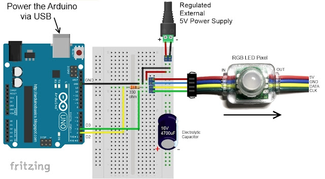
The following diagram demonstrates how to connect the RGB LED pixel Strand to the Arduino and to the External 5V power supply.


This diagram was created using Fritzing


Connection Instructions

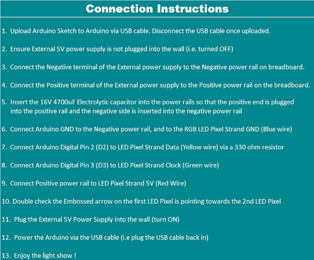
These instructions will help to guide you through the process of connecting your RGB LED pixel strand to the Arduino, and to the external power supply. The instructions assume that you will be powering the Arduino via a USB cable.


LightBox assembly

You will need to drill a 12mm hole into the craft timber box for each LED on the strand. It is worth taking the time to make accurate measurements before drilling the holes.
 
I made 12 holes for the outside circle pattern (12cm diameter), 6 holes for the inside circle pattern (8cm diameter), and a hole in the centre. I also made two holes at the front of the box, two on the left side, and two on the right side. I made one last hole at the back of the box for the 2.1mm DC power line socket.
 
Therefore you should have a total of 26 holes in the box. 25 of the holes are for the RGB LED pixel LEDs and one for the external power supply socket.
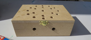
The lid of the box is about 19.5cm x 14.5cm long, which makes for a very tight squeeze. Probably too tight, because you have to account for the inner dimensions of the box. The inside of the box is used to house the Arduino, breadboard, the chipset side of the LEDs and cables/components. The inner dimensions of the box are 18cm x 13cm. Therefore, the housing for the LED chipset PCB (1.8cm x 2.5cm) prevented the box from closing. I used a Dremel to carve out the space required to close the lid.

Each LED is approximately 8cm apart on the strand, however, if you are really keen, you could cut the wires and extend them to any distance you require. But keep in mind that each LED is mounted on a small PCB (with a WS2801 chipset).You will therefore need to leave a minimum of 2cm between each 12mm hole to accomodate the size of the PCB+LED. If you plan carefully, you can probably squeeze a couple of LEDs within a distance of 1cm... but I would recommend that you give yourself a bit more room, because the PCBs are not square, and there is a good chance that you will have to start all over again.

In hindsight, I could have made the circle patterns a bit smaller, however I don't know if I could have packed these LEDs any closer. The diameter of the inner circle pattern must be at least 2cm smaller than the outer circle pattern. So I think "a bigger box" would have been the best option.

Once all of the holes have been drilled, paint and decorate the box to suit your style.

When the paint is dry, insert the LEDs into the drilled holes in number order.
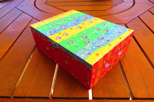
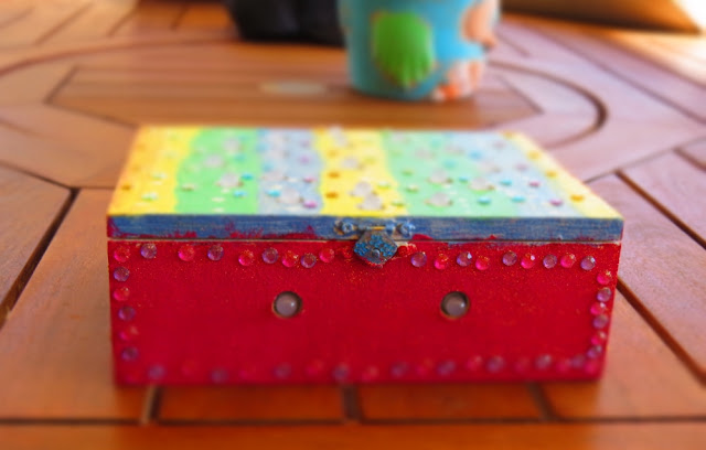
You can see the end result below.


Project Pictures

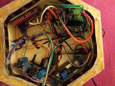
These pictures show the Light box after it has been drilled and painted. The LEDs have been inserted into their respective holes, and all wires + Arduino + breadboard are hidden within the box.


Concluding comments

Once you start writing LED animations for the RGB LED pixel Lightbox, it is very hard to stop. The colour combinations


If you like this page, please do me a favour and show your appreciation :

 
Visit my ArduinoBasics Google + page.
Follow me on Twitter by looking for ScottC @ArduinoBasics.
I can also be found on Pinterest and Instagram.
Have a look at my videos on my YouTube channel.


This project would not have been possible without OpenLab's collaborative effort.
Please visit their site for more cool projects.


However, if you do not have a google profile...
Feel free to share this page with your friends in any way you see fit.

Arduino LED Light Box

Description

Long straight lines of LED luminescence is nice, but sometimes you may want to light up something that has an unusual shape, or is not so linear. This is where the 12mm diffused flat digital RGB LED Pixels can come into play. This cool strand of 25 NeoPixels fit nicely into 12mm pre-drilled holes of any material you like.

This tutorial is dedicated to making a LED Light Box. I wanted the box to be equally as interesting during the day as it was at night. If you decide you make your own, feel free to be as creative as you want !! However, if you lack artistic acumen, you may need to source a minion or two.


Arduino Libraries and IDE

Before you start to hook up any components, upload the following sketch to the Arduino microcontroller. I am assuming that you already have the Arduino IDE installed on your computer. If not, the IDE can be downloaded from here.

The FastLED library is useful for simplifying the code for programming the NeoPixels. The latest "FastLED library" can be downloaded from here. I used FastLED library version 3.0.3 in this project.

If you have a different LED strip or your NeoPixels have a different chipset, make sure to change the relevant lines of code to accomodate your hardware. I would suggest you try out a few of the FastLED library examples before using the code below, so that you become more familiar with the library, and will be better equipped to make the necessary changes.

If you have a single strand of 25 Neopixels with the WS8201 chipset, then you will not have to make any modification below.


ARDUINO CODE:

Arduino Code Description

The code above will generate a randomised raindrop pattern on the NeoPixel LED Light box, however I have written code for a few more LED animations. These animations were written specifically for this light-box setup. In other words, once you have hooked everything up, you will be able to upload these other LED animations to the Arduino board without any further modification to the hardware/wiring, and yet experience a totally different light effect. You can find the code for the other animation effects by clicking on the links below:

  1. Breathing effect
  2. Ripple effect
  3. Clock effect
  4. Rotation effect
  5. Sweep effect
  6. Spiral effect
  7. Lightning effect
  8. Paparazzi in the Rain effect

Hooking it up:

Power requirements

Each Neopixel LED can draw up to 60 milliamps at maximum brightness (white). ie. 20 mA for each colour (red, green and blue). Therefore you should not try to power the LED strand directly from the Arduino, because the strand will draw too much current and damage the microcontroller(and possibly your USB port too). The LED strand will therefore need to be powered by a separate power supply. The power supply must supply the correct voltage (5V DC) and must also be able to supply sufficient current (1.5A or greater per strand of 25 LEDs).

Excessive voltage will damage or destroy your Neopixel strand. The LEDs will only draw as much current as they need, however your power supply must provide at least 1.5A or greater for each strand. If you chain two strands together, you will need a 5V 3A power supply.

Neopixel strand connection

There are 25 Neopixel LEDs per strand. Four of the wires at each end of the strand are terminated with a JST connector. The red wire is for power (VCC), blue wire for ground (GND), yellow wire is for Data, and green wire for Clock. A spare red wire (VCC) and a spare blue wire (GND) are attached to the ends of each strand for convenience, however, I did not use either. Please double check the colour of your wires... they may be different.

If you want to attach the LED strand to a breadboard, you can cut the JST connector off and use the Neopixel strand wires. Alternatively, if you would prefer to preserve the JST connector, you can simply insert jumper wires (or some male header pins) into the JST connector, and then plug them into the breadboard as required.

Each neopixel LED is individually controllable using two pins on your Arduino. The strand is directional. i.e. There is an INPUT side and an OUTPUT side. The strand should be connected such that wires from the microcontroller are attached to the INPUT side of the first neopixel. The arrows on each LED show the direction of data flow from INPUT to OUTPUT. The arrow on the first NeoPixel should be pointing towards the second NeoPixel, NOT towards the breadboard.

Other considerations

As a precaution, you should use a large capacitor across the + and - terminals of the power supply to prevent the initial onrush of current from damaging the Neopixels. I used a 4700uF 16V Electrolytic capacitor for this purpose. According to Adafruit, a 1000uF 6.3V capacitor (or higher) will also do the trick. You may also want to consider a 330 ohm resistor between the Arduino Digital pin and the strand's DATA pin.

If you want to power the Arduino using the regulated 5V external power supply. Disconnect the USB cable from the Arduino, and then connect the positive terminal of the power supply to the 5V pin on the Arduino. Be warned however, that excess voltage at this pin could damage your Arduino, because the 5V regulator will be bypassed.
 
Providing the USB cable is NOT connected to the Arduino, it should now be safe to plug the power supply into the wall. This setup will allow you to power the Neopixel strand and the Arduino using the same power supply.
 
WARNING: Never change any connections while the circuit is powered.

For more information about these NeoPixel strands, you may want to visit the Adafruit site. Adafruit was the source for most of these NeoPixel Strand precautions.


Fritzing diagram

The following diagram demonstrates how to connect the NeoPixel Strand to the Arduino and to the External 5V power supply.


This diagram was created using Fritzing


Connection Instructions

These instructions will help to guide you through the process of connecting your NeoPixel strand to the Arduino, and to the external power supply. The instructions assume that you will be powering the Arduino via a USB cable.


LightBox assembly

You will need to drill a 12mm hole into the craft timber box for each LED on the strand. It is worth taking the time to make accurate measurements before drilling the holes.
 
I made 12 holes for the outside circle pattern (12cm diameter), 6 holes for the inside circle pattern (8cm diameter), and a hole in the centre. I also made two holes at the front of the box, two on the left side, and two on the right side. I made one last hole at the back of the box for the 2.1mm DC power line socket.
 
Therefore you should have a total of 26 holes in the box. 25 of the holes are for the Neopixel LEDs and one for the external power supply socket.

The lid of the box is about 19.5cm x 14.5cm long, which makes for a very tight squeeze. Probably too tight, because you have to account for the inner dimensions of the box. The inside of the box is used to house the Arduino, breadboard, the chipset side of the LEDs and cables/components. The inner dimensions of the box are 18cm x 13cm. Therefore, the housing for the LED chipset PCB (1.8cm x 2.5cm) prevented the box from closing. I used a Dremel to carve out the space required to close the lid.

Each LED is approximately 8cm apart on the strand, however, if you are really keen, you could cut the wires and extend them to any distance you require. But keep in mind that each LED is mounted on a small PCB (with a WS2801 chipset).You will therefore need to leave a minimum of 2cm between each 12mm hole to accomodate the size of the PCB+LED. If you plan carefully, you can probably squeeze a couple of LEDs within a distance of 1cm... but I would recommend that you give yourself a bit more room, because the PCBs are not square, and there is a good chance that you will have to start all over again.

In hindsight, I could have made the circle patterns a bit smaller, however I don't know if I could have packed these LEDs any closer. The diameter of the inner circle pattern must be at least 2cm smaller than the outer circle pattern. So I think "a bigger box" would have been the best option.

Once all of the holes have been drilled, paint and decorate the box to suit your style.

When the paint is dry, insert the LEDs into the drilled holes in number order.
You can see the end result below.


Project Pictures

These pictures show the Light box after it has been drilled and painted. The LEDs have been inserted into their respective holes, and all wires + Arduino + breadboard are hidden within the box.


Concluding comments

Once you start writing LED animations for the NeoPixel Lightbox, it is very hard to stop. The colour combinations


If you like this page, please do me a favour and show your appreciation :

 
Visit my ArduinoBasics Google + page.
Follow me on Twitter by looking for ScottC @ArduinoBasics.
I can also be found on Pinterest and Instagram.
Have a look at my videos on my YouTube channel.


This project would not have been possible without OpenLab's collaborative effort.
Please visit their site for more cool projects.


However, if you do not have a google profile...
Feel free to share this page with your friends in any way you see fit.