Posts with «arduino code example» label

sprintf function

Description

This tutorial will help you to understand the sprintf function, and how to use it. Essentially, the sprintf function allows you to construct a string using a pre-formatted string template to which you can insert variables at pre-defined locations. The sprintf function will "compile" the string and assign it to a char array. All you have to do is make sure that the char array is large enough to hold all of the characters in the string. The best way to understand the sprintf function is with examples. And luckily, I have examples. What are we waiting for ? Let's dive in.

Parts Required: an Arduino and a USB cable.


sprintf ( char* array,   const char* strTemplate,   var1...);


Arduino IDE

While there are many Arduino IDE alternatives out there, I would recommend that you use the official Arduino IDE for this project. I used the official Arduino IDE app (v1.8.5) for Windows 10.
Make sure to get the most up-to-date version for your operating system here.


Arduino Code

The code below will show you how to use the sprintf function and includes a number of different format specifiers to play with. In each case the sprintf function writes to the "data" character array, and subsequently sends it through to the Serial monitor. The string template helps to construct the data output, allowing you to insert variables at specific locations within the text. The format of the variable is defined by the "format specifier" used in the sprintf function. The format specifier is always prefixed with a percentage sign (%).


Serial Monitor Output

  1. Upload the code to the Arduino.
  2. Open the Serial monitor in the Arduino IDE (Ctrl+Shift+M).
  3. Ensure that you have set the baud rate in the Serial monitor to 9600.
  4. You should see the following output:


The sprintf function requires that you have a character array to store the output. In the example code above, the output is stored in the "data" character array. It also requires a template that tells the function where to insert the variables. As you can see from the table below, the variables will be formatted based on the format specifier used. The format specifier can be quite useful for numeric conversions. Eg. decimal to hex conversions.


Format Specifiers

Some of the different format specifiers that can be used with the sprinf function are listed below.

Conclusion

Now that you know all about the sprintf function, I hope it will inspire you to use it in your own projects. Please let me know in the comments below how you use the sprintf function, and whether there was anything that you feel I failed to mention in this tutorial.
Happy Coding !!


If you found this tutorial helpful, please consider supporting me by buying me a virtual coffee/beer.

$3.00 AUD only
 

Social Media

You can find me on various social networks:

Follow me on Twitter: ScottC @ArduinoBasics.
I can also be found on Instagram, Pinterest, and YouTube.
And if all else fails, I have a server on Discord.


Arduino LED Light Box

Description

Long straight lines of LED luminescence is nice, but sometimes you may want to light up something that has an unusual shape, or is not so linear. This is where the 12mm diffused flat digital RGB LED Pixels can come into play. This cool strand of 25 RGB LED pixels fit nicely into 12mm pre-drilled holes of any material you like.

This tutorial is dedicated to making a LED Light Box. I wanted the box to be equally as interesting during the day as it was at night. If you decide you make your own, feel free to be as creative as you want !! However, if you lack artistic acumen, you may need to source a minion or two.


Arduino Libraries and IDE

Before you start to hook up any components, upload the following sketch to the Arduino microcontroller. I am assuming that you already have the Arduino IDE installed on your computer. If not, the IDE can be downloaded from here.

The FastLED library is useful for simplifying the code for programming the RGB LED pixels. The latest "FastLED library" can be downloaded from here. I used FastLED library version 3.0.3 in this project.

If you have a different LED strip or your RGB LED pixels have a different chipset, make sure to change the relevant lines of code to accomodate your hardware. I would suggest you try out a few of the FastLED library examples before using the code below, so that you become more familiar with the library, and will be better equipped to make the necessary changes.

If you have a single strand of 25 RGB LED pixels with the WS8201 chipset, then you will not have to make any modification below.


ARDUINO CODE:

Arduino Code Description

The code above will generate a randomised raindrop pattern on the Arduino LED Light box, however I have written code for a few more LED animations. These animations were written specifically for this light-box setup. In other words, once you have hooked everything up, you will be able to upload these other LED animations to the Arduino board without any further modification to the hardware/wiring, and yet experience a totally different light effect. You can find the code for the other animation effects by clicking on the links below:

  1. Breathing effect
  2. Ripple effect
  3. Clock effect
  4. Rotation effect
  5. Sweep effect
  6. Spiral effect
  7. Lightning effect
  8. Paparazzi in the Rain effect

Hooking it up:

Power requirements

Each LED pixel can draw up to 60 milliamps at maximum brightness (white). ie. 20 mA for each colour (red, green and blue). Therefore you should not try to power the LED strand directly from the Arduino, because the strand will draw too much current and damage the microcontroller(and possibly your USB port too). The LED strand will therefore need to be powered by a separate power supply. The power supply must supply the correct voltage (5V DC) and must also be able to supply sufficient current (1.5A or greater per strand of 25 LEDs).

Excessive voltage will damage or destroy your LED pixel strand. The LEDs will only draw as much current as they need, however your power supply must provide at least 1.5A or greater for each strand. If you chain two strands together, you will need a 5V 3A power supply.

RGB LED pixel strand connection

There are 25 LED pixels per strand. Four of the wires at each end of the strand are terminated with a JST connector. The red wire is for power (VCC), blue wire for ground (GND), yellow wire is for Data, and green wire for Clock. A spare red wire (VCC) and a spare blue wire (GND) are attached to the ends of each strand for convenience, however, I did not use either. Please double check the colour of your wires... they may be different.

If you want to attach the LED strand to a breadboard, you can cut the JST connector off and use the LED pixel strand wires. Alternatively, if you would prefer to preserve the JST connector, you can simply insert jumper wires (or some male header pins) into the JST connector, and then plug them into the breadboard as required.

Each LED pixel is individually controllable using two pins on your Arduino. The strand is directional. i.e. There is an INPUT side and an OUTPUT side. The strand should be connected such that wires from the microcontroller are attached to the INPUT side of the first LED pixel. The arrows on each LED show the direction of data flow from INPUT to OUTPUT. The arrow on the first LED pixel should be pointing towards the second LED pixel, NOT towards the breadboard.

Other considerations

As a precaution, you should use a large capacitor across the + and - terminals of the power supply to prevent the initial onrush of current from damaging the RGB LED pixels. I used a 4700uF 16V Electrolytic capacitor for this purpose. According to Adafruit, a 1000uF 6.3V capacitor (or higher) will also do the trick. You may also want to consider a 330 ohm resistor between the Arduino Digital pin and the strand's DATA pin.

If you want to power the Arduino using the regulated 5V external power supply. Disconnect the USB cable from the Arduino, and then connect the positive terminal of the power supply to the 5V pin on the Arduino. Be warned however, that excess voltage at this pin could damage your Arduino, because the 5V regulator will be bypassed.
 
Providing the USB cable is NOT connected to the Arduino, it should now be safe to plug the power supply into the wall. This setup will allow you to power the RGB LED pixel strand and the Arduino using the same power supply.
 
WARNING: Never change any connections while the circuit is powered.

For more information about these RGB LED pixel strands, you may want to visit the Adafruit site. Adafruit was the source for most of these RGB LED pixel Strand precautions.
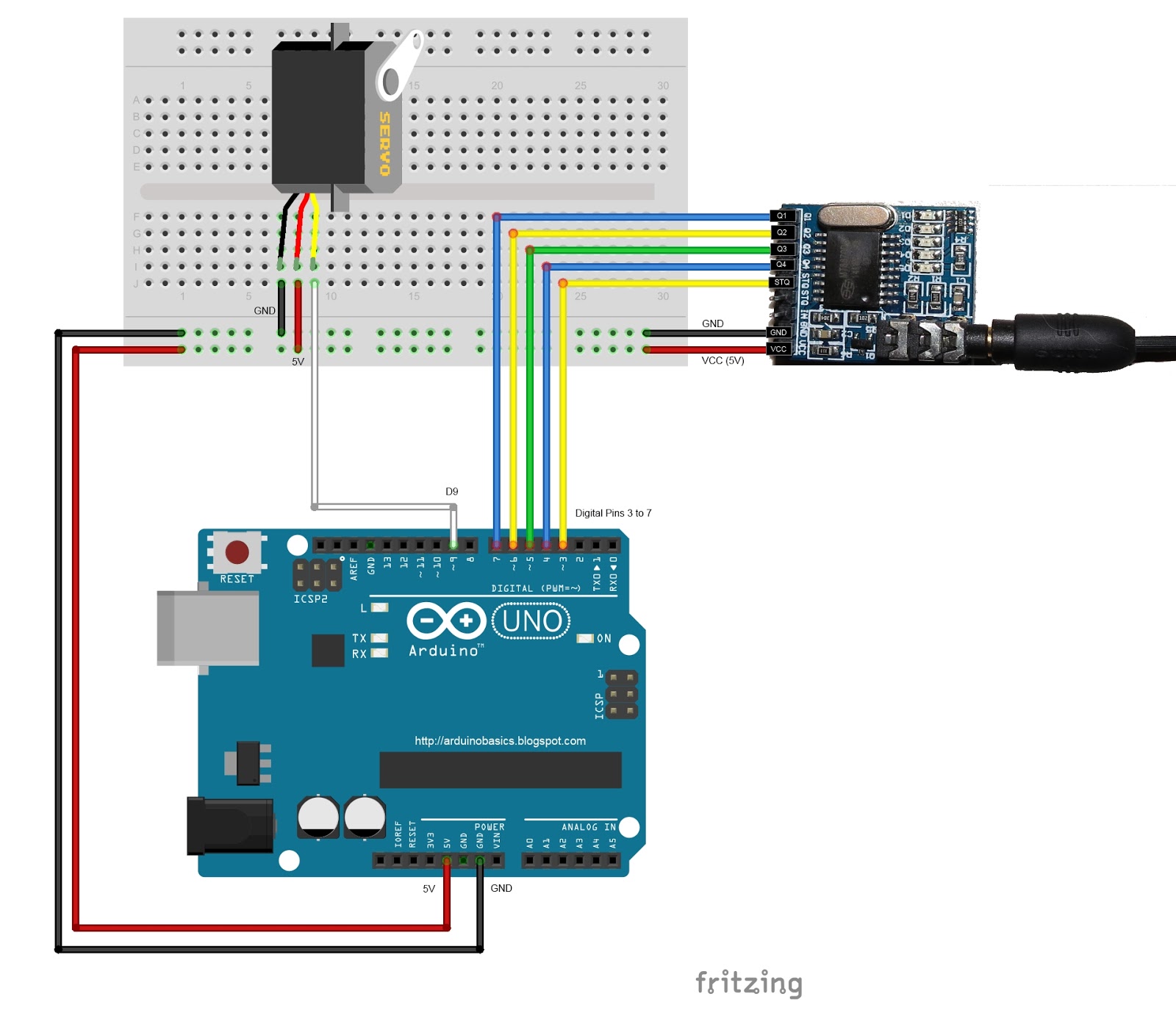

Fritzing diagram

The following diagram demonstrates how to connect the RGB LED pixel Strand to the Arduino and to the External 5V power supply.


This diagram was created using Fritzing


Connection Instructions

These instructions will help to guide you through the process of connecting your RGB LED pixel strand to the Arduino, and to the external power supply. The instructions assume that you will be powering the Arduino via a USB cable.
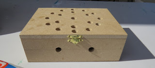


LightBox assembly

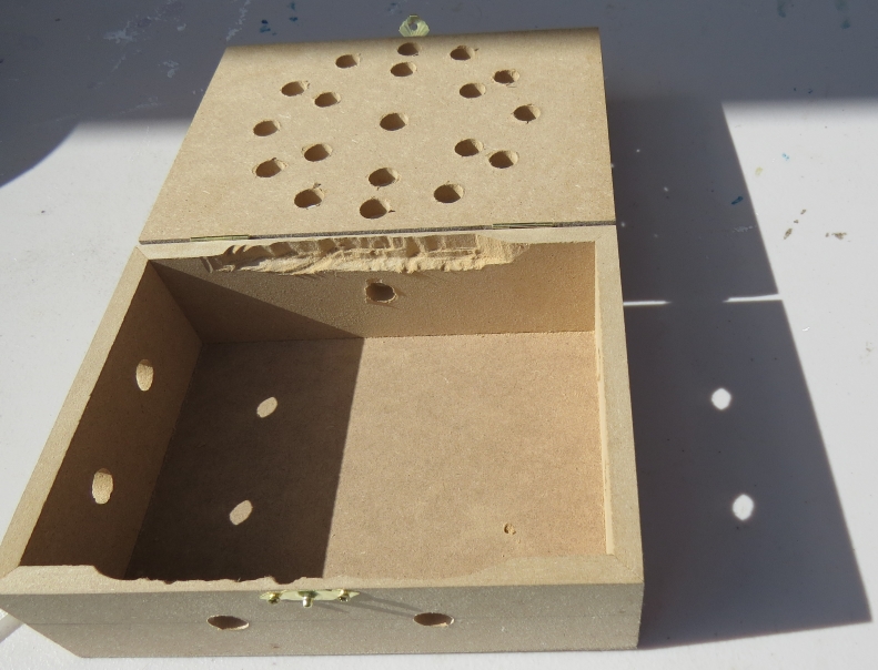
You will need to drill a 12mm hole into the craft timber box for each LED on the strand. It is worth taking the time to make accurate measurements before drilling the holes.
 
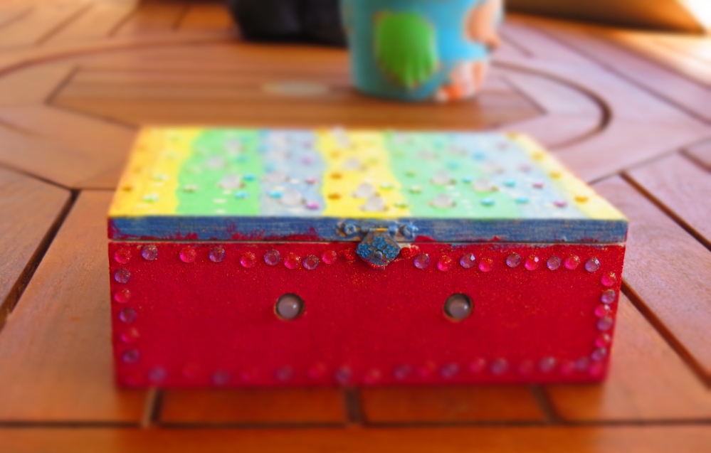
I made 12 holes for the outside circle pattern (12cm diameter), 6 holes for the inside circle pattern (8cm diameter), and a hole in the centre. I also made two holes at the front of the box, two on the left side, and two on the right side. I made one last hole at the back of the box for the 2.1mm DC power line socket.
 
Therefore you should have a total of 26 holes in the box. 25 of the holes are for the RGB LED pixel LEDs and one for the external power supply socket.

The lid of the box is about 19.5cm x 14.5cm long, which makes for a very tight squeeze. Probably too tight, because you have to account for the inner dimensions of the box. The inside of the box is used to house the Arduino, breadboard, the chipset side of the LEDs and cables/components. The inner dimensions of the box are 18cm x 13cm. Therefore, the housing for the LED chipset PCB (1.8cm x 2.5cm) prevented the box from closing. I used a Dremel to carve out the space required to close the lid.

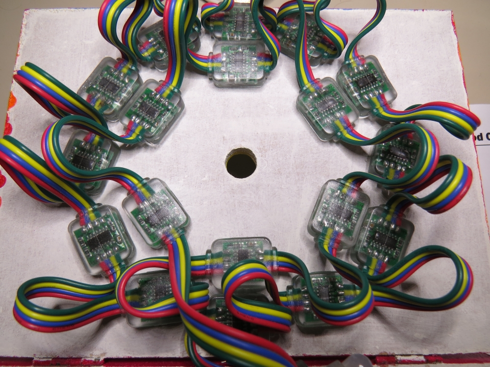
Each LED is approximately 8cm apart on the strand, however, if you are really keen, you could cut the wires and extend them to any distance you require. But keep in mind that each LED is mounted on a small PCB (with a WS2801 chipset).You will therefore need to leave a minimum of 2cm between each 12mm hole to accomodate the size of the PCB+LED. If you plan carefully, you can probably squeeze a couple of LEDs within a distance of 1cm... but I would recommend that you give yourself a bit more room, because the PCBs are not square, and there is a good chance that you will have to start all over again.

In hindsight, I could have made the circle patterns a bit smaller, however I don't know if I could have packed these LEDs any closer. The diameter of the inner circle pattern must be at least 2cm smaller than the outer circle pattern. So I think "a bigger box" would have been the best option.

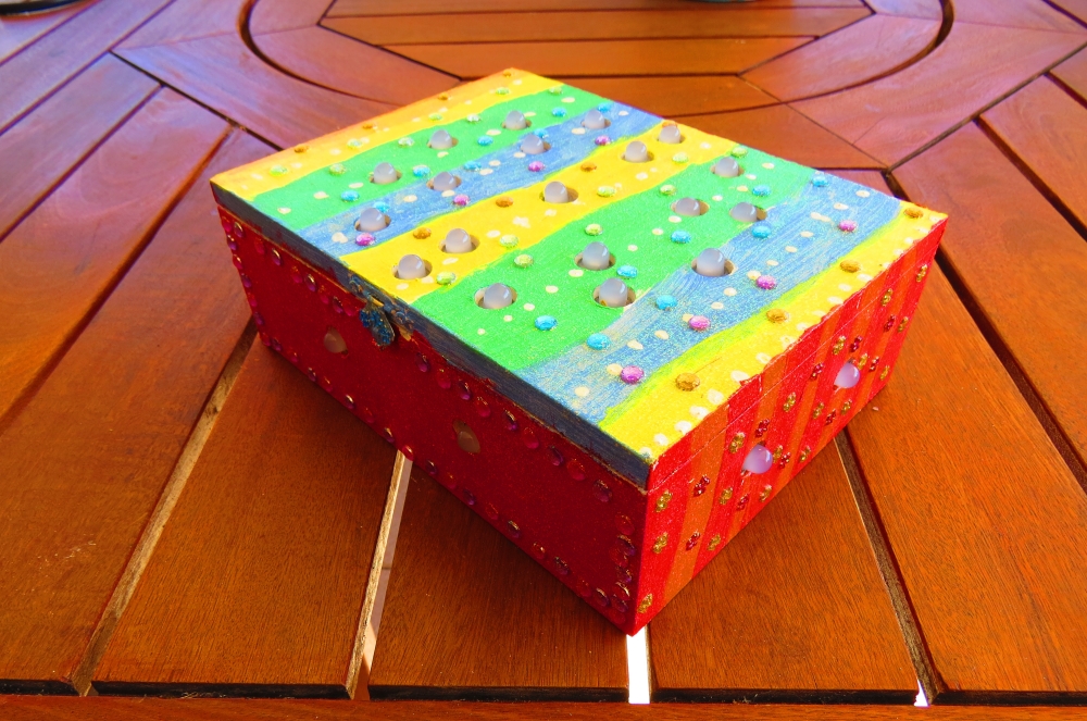
Once all of the holes have been drilled, paint and decorate the box to suit your style.

When the paint is dry, insert the LEDs into the drilled holes in number order.
You can see the end result below.


Project Pictures

These pictures show the Light box after it has been drilled and painted. The LEDs have been inserted into their respective holes, and all wires + Arduino + breadboard are hidden within the box.


Concluding comments

Once you start writing LED animations for the RGB LED pixel Lightbox, it is very hard to stop. The colour combinations


If you like this page, please do me a favour and show your appreciation :

 
Visit my ArduinoBasics Google + page.
Follow me on Twitter by looking for ScottC @ArduinoBasics.
I can also be found on Pinterest and Instagram.
Have a look at my videos on my YouTube channel.


This project would not have been possible without OpenLab's collaborative effort.
Please visit their site for more cool projects.


However, if you do not have a google profile...
Feel free to share this page with your friends in any way you see fit.

MT8870 DTMF - Dual Tone Multi Frequency Decoder

Project Description

We will be using an MT8870 DTMF module with an Arduino UNO to control a small servo motor in this project. The DTMF module gives the Arduino super-powers and allows you to control the Servo motor in so many ways. For example, this tutorial will show you how to control the servo motor using:
  • a YouTube Video
  • a voice recorder
  • A web application (Online tone generator)
  • A smart phone app (DTMF Pad)
  • A touch-tone phone to cell-phone call
All of these control methods will take advantage of the same exact Arduino code/sketch. But how???
The MT8870 DTMF decoder is quite a neat little module that allows you incorporate DTMF technology into your arduino projects. DTMF stands for Dual-Tone Multi-Frequency. DTMF tones are commonly associated with touch-tone phones and other telecommunication systems. When you press the number "1" on a touch-tone phone, two sine waves with frequencies: 697Hz and 1209Hz are combined to produce a unique DTMF signal which can be transmitted through the phone line. The MT8870 DTMF module can take this signal as an input, and decode it to produce a binary output.


The DTMF module does not care how you produce the DTMF tone. However, if it receives this tone, it will decode it. We can take advantage of this feature to supply the module with tones from different sources. The module has a 3.5mm port for line input. Providing you can connect your DTMF source to this line input in some way, it should work. I must warn you, however that this is a line input and NOT a microphone input. If you wanted to use a microphone, you will need to boost or amplify the signal before sending it to the DTMF module.
 
You will need the following parts for this project
 

Parts Required:

Software/Apps Required

Arduino Sketch


Upload the following sketch to the Arduino.
 

1
2
3
4
5
6
7
8
9
10
11
12
13
14
15
16
17
18
19
20
21
22
23
24
25
26
27
28
29
30
31
32
33
34
35
36
37
38
39
40
41
42
43
44
45
46
47
48
49
50
51
52
53
54
55
56
57
58
59
60
61
62
/* ================================================================================================================================================== Project: MT8870 DTMF Servo sketch Author: Scott C Created: 4th August 2015 Arduino IDE: 1.6.4 Website: http://arduinobasics.blogspot.com/p/arduino-basics-projects-page.html Description: This project will allow you to control a Servo motor using an Arduino UNO and a MT8870 DTMF Module. The DTMF signal is received through the 3.5mm port of the DTMF module and is decoded. We will use the decoded output to control the position of the Servo. A SG-5010 Servo motor was used in this project. ===================================================================================================================================================== *///This sketch uses the Servo library that comes with the Arduino IDE #include <Servo.h> //Global variables----------------------------------------------------------------------------------------- Servo SG5010; // The SG5010 variable provides Servo functionality int servoPosition = 0; // The servoPosition variable will be used to set the position of the servo byte DTMFread; // The DTMFread variable will be used to interpret the output of the DTMF module. const int STQ = 3; // Attach DTMF Module STQ Pin to Arduino Digital Pin 3 const int Q4 = 4; // Attach DTMF Module Q4 Pin to Arduino Digital Pin 4 const int Q3 = 5; // Attach DTMF Module Q3 Pin to Arduino Digital Pin 5 const int Q2 = 6; // Attach DTMF Module Q2 Pin to Arduino Digital Pin 6 const int Q1 = 7; // Attach DTMF Module Q1 Pin to Arduino Digital Pin 7 /*========================================================================================================= setup() : will setup the Servo, and prepare the Arduino to receive the MT8700 DTMF module's output. ========================================================================================================== */void setup() { SG5010.attach(9); // The Servo signal cable will be attached to Arduino Digital Pin 9 SG5010.write(servoPosition); // Set the servo position to zero. //Setup the INPUT pins on the Arduino pinMode(STQ, INPUT); pinMode(Q4, INPUT); pinMode(Q3, INPUT); pinMode(Q2, INPUT); pinMode(Q1, INPUT);} /*========================================================================================================= loop() : Arduino will interpret the DTMF module output and position the Servo accordingly ========================================================================================================== */void loop() { if(digitalRead(STQ)==HIGH){ //When a DTMF tone is detected, STQ will read HIGH for the duration of the tone. DTMFread=0; if(digitalRead(Q1)==HIGH){ //If Q1 reads HIGH, then add 1 to the DTMFread variable DTMFread=DTMFread+1; } if(digitalRead(Q2)==HIGH){ //If Q2 reads HIGH, then add 2 to the DTMFread variable DTMFread=DTMFread+2; } if(digitalRead(Q3)==HIGH){ //If Q3 reads HIGH, then add 4 to the DTMFread variable DTMFread=DTMFread+4; } if(digitalRead(Q4)==HIGH){ //If Q4 reads HIGH, then add 8 to the DTMFread variable DTMFread=DTMFread+8; } servoPosition = DTMFread * 8.5; //Set the servoPosition varaible to the combined total of all the Q1 to Q4 readings. Multiply by 8.5 to amplify the servo rotation. } SG5010.write(servoPosition); //Set the servo's position according to the "servoPosition" variable. }


Fritzing Sketch


Connect the Arduino to the MT8870 DTMF module, and to a Servo.
Use the following Fritzing sketch as a guide.
 
(Click the image above to enlarge it)


Discussion


You will need to connect a cable from the DTMF module's 3.5mm port to that of your smart phone, computer, voice recorder or any other DTMF source of your choice.


When you power up your Arduino, the Servo motor should turn all the way to the left to it's zero position. Once the DTMF module receives a DTMF signal, it will identify the relevant frequecies as described in the table at the beginning of this tutorial, and produce a binary like output. You will notice the DTMF module's onboard LEDs light up when a tone is detected. Onboard LED (D5) will turn on for the length of the DTMF tone it just received, and turn off when the tone has stopped. On the other hand, the onboard LEDs (D1 to D4) will light up depending on the tone received, and will remain lit until the module receives another tone. The onboard LEDs are a visual representation of the voltages applied to the DTMF module's pins (Q1 to Q4, and STQ). Q1 matches D1, Q2 matches D2 etc etc. and STQ matches D5.
 
You will notice that there are two STQ pins on the DTMF module. The STQ pin that is closest to Q4 will only go high when a DTMF tone is detected, and will remain high for the duration of the tone. The other STQ pin is the exact opposite. It will switch LOW when a tone is received and remain LOW for the duration of the tone. When there is no tone, this STQ pin will remain HIGH. The table below provides a summary of the DTMF module outputs, with a blue box representing a voltage applied to that pin (HIGH), whereas a black box indicates no voltage applied (LOW).


In order to follow this project, you need a source of DTMF tones. You can produce DTMF tones using a touch-tone phone, or through the use of a DTMF Pad app. If you are feeling creative, you can create a DTMF song/tune like the one I posted on YouTube. You can see the video below:


As you can see from the video, I also recorded the DTMF tune onto a voice recorder, and was able to control the servo that way. If you are not feeling creative, you can visit this website to create DTMF tones from your browser.

Concluding comments


This project was very fun, and shows some novel ways to control your Arduino. After completing the project, I realised that I could use this module to alert me when new emails or messages arrive on my phone or computer. If you have the ability to change the email or message notification sound to a DTMF tone, you should be able to get the module and Arduino to respond accordingly. Oh well, maybe I'll save that project for another day.
 
If this project helped you in anyway or if you use my code within your project, please let me know in the comments below. I would be interested to see what you did.


If you like this page, please do me a favour and show your appreciation :

 
Visit my ArduinoBasics Google + page.
Follow me on Twitter by looking for ScottC @ArduinoBasics.
I can also be found on Pinterest and Instagram.
Have a look at my videos on my YouTube channel.


However, if you do not have a google profile...
Feel free to share this page with your friends in any way you see fit.