Posts with «tronixstuff» label

Hewlett-Packard 5082-7415 LED Display from 1976

In this article we examine a five digit, seven-segment LED display from Hewlett-Packard, the 5082-7415:

We realise they’re most likely now pure unobtanium, but we like some old display p0rn so here you go.

2025 update – Tronixlabs in Australia has a limited quantity of new, old-stock four-digit QDSP6064 displays. Email john at tronixlabs dot com for more information.

According to the data sheet (HP 5082-series.pdf) and other research this was available for a period of time around 1976 and used with other 5082-series modules in other HP products. Such as the Hewlett-Packard 3x series of calculators, for example:

Using the display is very easy – kudos to the engineers at HP for making a simple design that could be reusable in many applications. The 5082-7415 is a common-cathode unit and wiring is very simple – there are the usual eight anodes for segments a~f and the decimal point, and the five cathodes.

As this module isn’t too easily replaceable, I was very conservative with the power supply – feeding just under 1.6V at 10mA to each of the anode pins. A quick test proved very promising:

Excellent – it worked! But now to get it displaying some sort of interesting way. Using the following hardware…

Don’t forget to use the data sheet (HP 5082-series.pdf). You don’t have to use Arduino – any microcontroller with the appropriate I/O can take care of this.

Here is a simple Arduino sketch that scrolls through the digits with and then without the decimal point:

// Arduino sketch to demonstrate HP 5082-7415 LED Display unit
// John Boxall, April 2012
int clockPin=6;
int latchPin=7;
int dataPin=8;
// array for cathodes - sent to second shift register
byte digits[]={
  B10000000,
  B01000000,
  B00100000,
  B00010000,
  B00001000,
  B11111000}; // use digits[6] to turn all on
// array for anodes (to display 0~0) - sent to first shift register
byte numbers[]={
  B11111100,
  B01100000,
  B11011010,
  B11110010,
  B01100110,
  B10110110,
  B10111110,
  B11100000,
  B11111110,
  B11110110};
void setup()
{
  pinMode(clockPin, OUTPUT);
  pinMode(latchPin, OUTPUT);
  pinMode(dataPin, OUTPUT);
}
void loop()
{
  int i;
  for ( i=0 ; i<10; i++ )
  {
    digitalWrite(latchPin, LOW);
    shiftOut(dataPin, clockPin, LSBFIRST, digits[6]);
    shiftOut(dataPin, clockPin, LSBFIRST, numbers[i]);
    digitalWrite(latchPin, HIGH);
    delay(250);
  }
  // now repeat with decimal point
  for ( i=0 ; i<10; i++ )
  {
    digitalWrite(latchPin, LOW);
    shiftOut(dataPin, clockPin, LSBFIRST, digits[6]);
    shiftOut(dataPin, clockPin, LSBFIRST, numbers[i]+1);
    digitalWrite(latchPin, HIGH);
    delay(250);
  }
}

And the results:

Now for something more useful. Here is a function that sends a single digit to a position on the display with the option of turning the decimal point on or off:

void displayDigit(int value, int posit, boolean decPoint)
// displays integer value at digit position posit with decimal point on/off
{
 digitalWrite(latchPin, LOW);
 shiftOut(dataPin, clockPin, LSBFIRST, digits[posit]);
 if (decPoint==true)
 {
 shiftOut(dataPin, clockPin, LSBFIRST, numbers[value]+1); 
 } 
 else 
 {
 shiftOut(dataPin, clockPin, LSBFIRST, numbers[value]); 
 }
 digitalWrite(latchPin, HIGH);
}

So if you wanted to display the number three in the fourth digit, with the decimal point – use

displayDigit(3,3,true);

with the following result:

We make use of the displayDigit() function in our next sketch. We introduce a new function:

displayInteger(number,cycles);

It accepts a long integer between zero and 99999 (number) and displays it on the module for cycles times:

// Arduino sketch to demonstrate HP 5082-7415 LED Display unit
// Displays numbers on request
// John Boxall, April 2012
int clockPin=6;
int latchPin=7;
int dataPin=8;
// array for cathodes - sent to second shift register
byte digits[]={
 B10000000,
 B01000000,
 B00100000,
 B00010000,
 B00001000,
 B11111000}; // use digits[6] to turn all on
// array for anodes (to display 0~0) - sent to first shift register
byte numbers[]={
 B11111100,
 B01100000,
 B11011010,
 B11110010,
 B01100110,
 B10110110,
 B10111110,
 B11100000,
 B11111110,
 B11110110};
void setup()
{
 pinMode(clockPin, OUTPUT);
 pinMode(latchPin, OUTPUT);
 pinMode(dataPin, OUTPUT);
 randomSeed(analogRead(0));
}
void clearDisplay()
// turns off all digits
{
 digitalWrite(latchPin, LOW);
 shiftOut(dataPin, clockPin, LSBFIRST, 0);
 shiftOut(dataPin, clockPin, LSBFIRST, 0); 
 digitalWrite(latchPin, HIGH);
}
void displayDigit(int value, int posit, boolean decPoint)
// displays integer value at digit position posit with decimal point on/off
{
 digitalWrite(latchPin, LOW);
 shiftOut(dataPin, clockPin, LSBFIRST, digits[posit]);
 if (decPoint==true)
 {
 shiftOut(dataPin, clockPin, LSBFIRST, numbers[value]+1); 
 } 
 else 
 {
 shiftOut(dataPin, clockPin, LSBFIRST, numbers[value]); 
 }
 digitalWrite(latchPin, HIGH);
}
void displayInteger(long number,int cycles)
// displays a number 'number' on the HP display. 
{
 long i,j,k,l,z;
 float f;
 clearDisplay();
 for (z=0; z
void loop()
{
 long l2;
 l2=random(0,100001);
 displayInteger(l2,400);
}

For demonstration purposes the sketch displays random numbers, as shown in the video below:

Update – four-digit versions…

They worked very nicely and can be driven in the same method as the 5082-7415s described earlier. In the following video we have run the same sketches with the new displays:

In the meanwhile, I hope you found this article of interest. Thanks to the Vintage Technology Association website and the Museum of HP Calculators for background information.

To keep up to date with new posts at tronixstuff.com, please subscribe to the mailing list in the box on the right, or follow us on x – @tronixstuff.

I hope you enjoyed reading about the displays. If you find this sort of thing interesting, please consider ordering one or more of my books from amazon.

And as always, have fun and make something.

Tutorial – Ethernet Shields and Arduino

In this chapter we will introduce and examine the use of Ethernet networking with Arduino over local networks and the greater Internet.

It will be assumed that you have a basic understanding of computer networking, such as the knowledge of how to connect computers to a hub/router with RJ45 cables, what an IP and MAC address is, and so on. Furthermore, here is a good quick rundown about Ethernet.

Getting Started

You will need an Arduino Uno or compatible board with an Ethernet shield that uses the W5100 Ethernet controller IC (pretty much all of them):

Furthermore you will need to power the board via the external DC socket – the W5100 IC uses more current than the USB power can supply. A 9V 1.5A plug pack/wall wart will suffice.

Finally it does get hot – so be careful not to touch the W5100 after extended use. In case you’re not sure – this is the W5100 IC:

Once you have your Ethernet-enabled Arduino, and have the external power connected – it’s a good idea to check it all works. Open the Arduino IDE and select File > Examples > Ethernet > Webserver. This loads a simple sketch which will display data gathered from the analogue inputs on a web browser. However don’t upload it yet, it needs a slight modification.

You need to specify the IP address of the Ethernet shield – which is done inside the sketch. This is simple, go to the line:

IPAddress ip(192,168,1, 177);

And alter it to match your own setup. For example, in my home the router’s IP address is 10.1.1.1, the printer is 10.1.1.50 and all PCs are below …50. So I will set my shield IP to 10.1.1.77 by altering the line to:

IPAddress ip(10,1,1,77);

You also have the opportunity to change your MAC address. Each piece of networking equipment has a unique serial number to identify itself over a network, and this is normall hard-programmed into the equipments’ firmware. However with Arduino we can define the MAC address ourselves.

If you are running more than one Ethernet shield on your network, ensure they have different MAC addresses by altering the hexadecimal values in the line:

byte mac[] = { 0xDE, 0xAD, 0xBE, 0xEF, 0xFE, 0xED };

However if you only have one shield just leave it be. There may be the very, very, statistically rare chance of having a MAC address the same as your existing hardware, so that would be another time to change it.

Once you have made your alterations, save and upload the sketch. Now open a web browser and navigate to the IP address you entered in the sketch, and you should be presented with something similar to the following:

What’s happening? The Arduino has been programmed to offer a simple web page with the values measured by the analogue inputs. You can refresh the browser to get updated values.

At this point – please note that the Ethernet shields use digital pins 10~13, so you can’t use those for anything else. Some Arduino Ethernet shields may also have a microSD card socket, which also uses another digital pin – so check with the documentation to find out which one.

Nevertheless, now that we can see the Ethernet shield is working we can move on to something more useful. Let’s dissect the previous example in a simple way, and see how we can distribute and display more interesting data over the network. For reference, all of the Ethernet-related functions are handled by the Ethernet Arduino library. If you examine the previous sketch we just used, the section that will be of interest is:

 for (int analogChannel = 0; analogChannel < 6; analogChannel++) 
          {
            int sensorReading = analogRead(analogChannel);
            client.print("analog input ");
            client.print(analogChannel);
            client.print(" is ");
            client.print(sensorReading);
            client.println("<br />");       
          }
          client.println("</html>");

Hopefully this section of the sketch should be familiar – remember how we have used serial.print(); in the past when sending data to the serial monitor box? Well now we can do the same thing, but sending data from our Ethernet shield back to a web browser – on other words, a very basic type of web page.

However there is something you may or may not want to  learn in order to format the output in a readable format – HTML code. I am not a website developer (!) so will not delve into HTML too much.

However if you wish to serve up nicely formatted web pages with your Arduino and so on, here would be a good start. In the interests of simplicity, the following two functions will be the most useful:

client.print(" is ");

Client.print (); allows us to send text or data back to the web page. It works in the same way as serial.print(), so nothing new there. You can also specify the data type in the same way as with serial.print(). Naturally you can also use it to send data back as well. The other useful line is:

client.println("<br />");

which sends the HTML code back to the web browser telling it to start a new line. The part that actually causes the carriage return/new line is the <br /> which is an HTML code (or “tag”) for a new line. So if you are creating more elaborate web page displays, you can just insert other HTML tags in the client.print(); statement.

If you want to learn more about HTML commands, here’s a good tutorial site. Finally – note that the sketch will only send the data when it has been requested, that is when it has received a request from the web browser.

Accessing your Arduino over the Internet

So far – so good. But what if you want to access your Arduino from outside the local network?

You will need a static IP address – that is, the IP address your internet service provider assigns to your connection needs to stay the same. If you don’t have a static IP, as long as you leave your modem/router permanently swiched on your IP shouldn’t change. However that isn’t an optimal solution.

If your ISP cannot offer you a static IP at all, you can still move forward with the project by using an organisation that offers a Dynamic DNS. These organisations offer you your own static IP host name (e.g. mojo.monkeynuts.com) instead of a number, keep track of your changing IP address and linking it to the new host name. From what I can gather, your modem needs to support (have an in-built client for…) these DDNS services. As an example, two companies are No-IP andDynDNS.com. Please note that I haven’t used those two, they are just offered as examples.

Now, to find your IP address… usually this can be found by logging into your router’s administration page – it is usually 192.168.0.1 but could be different. Check with your supplier or ISP if they supplied the hardware. For this example, if I enter 10.1.1.1 in a web browser, and after entering my modem administration password, the following screen is presented:

What you are looking for is your WAN IP address, as you can see in the image above. To keep the pranksters away, I have blacked out some of my address.

The next thing to do is turn on port-forwarding. This tells the router where to redirect incoming requests from the outside world. When the modem receives such a request, we want to send that request to the port number of our Ethernet shield. Using the:

EthernetServer server(125);

function in our sketch has set the port number to 125. Each modem’s configuration screen will look different, but as an example here is one:

So you can see from the line number one in the image above, the inbound port numbers have been set to 125, and the IP address of the Ethernet shield has been set to 10.1.1.77 – the same as in the sketch.

After saving the settings, we’re all set. The external address of my Ethernet shield will be the WAN:125, so to access the Arduino I will type my WAN address with :125 at the end into the browser of the remote web device, which will contact the lonely Ethernet hardware back home.

Furthermore, you may need to alter your modem’s firewall settings, to allow the port 125 to be “open” to incoming requests. Please check your modem documentation for more information on how to do this.

Now from basically any Internet connected device in the free world, I can enter my WAN and port number into the URL field and receive the results. For example, from a phone when it is connected to the Internet via LTE mobile data:

So at this stage you can now display data on a simple web page created by your Arduino and access it from anywhere with unrestricted Internet access. With your previous Arduino knowledge you can now use data from sensors or other parts of a sketch and display it for retrieval.

Displaying sensor data on a web page

As an example of displaying sensor data on a web page, let’s use an inexpensive and popular temperature and humidity sensor – the DHT22. You will need to install the DHT22 Arduino library which can be found on this page. If this is your first time with the DHT22, experiment with the example sketch that’s included with the library so you understand how it works.

Connect the DHT22 with the data pin to Arduino D2, Vin to the 5V pin and GND to … GND.

Now for our sketch – to display the temperature and humidity on a web page. If you’re not up on HTML you can use online services such as this to generate the code, which you can then modify to use in the sketch.

In the example below, the temperature and humidity data from the DHT22 is served in a simple web page:

#include <SPI.h>
#include <Ethernet.h>

// for DHT22 sensor
#include "DHT.h"
#define DHTPIN 2
#define DHTTYPE DHT22

// Enter a MAC address and IP address for your controller below.
// The IP address will be dependent on your local network:
byte mac[] = {   0xDE, 0xAD, 0xBE, 0xEF, 0xFE, 0xED };
IPAddress ip(10,1,1,77);

// Initialize the Ethernet server library
// with the IP address and port you want to use 
// (port 80 is default for HTTP):
EthernetServer server(125);
DHT dht(DHTPIN, DHTTYPE);

void setup() 
{
  dht.begin();
 // Open serial communications and wait for port to open:
  Serial.begin(9600);
   while (!Serial) {
    ; // wait for serial port to connect. Needed for Leonardo only
  }
  // start the Ethernet connection and the server:
  Ethernet.begin(mac, ip);
  server.begin();
  Serial.print("server is at ");
  Serial.println(Ethernet.localIP());
}

void loop() 
{
  // listen for incoming clients
  EthernetClient client = server.available();
  if (client) {
    Serial.println("new client");
    // an http request ends with a blank line
    boolean currentLineIsBlank = true;
    while (client.connected()) {
      if (client.available()) {
        char c = client.read();
        Serial.write(c);
        // if you've gotten to the end of the line (received a newline
        // character) and the line is blank, the http request has ended,
        // so you can send a reply
        if (c == 'n' && currentLineIsBlank) 
        {
          // send a standard http response header
          client.println("HTTP/1.1 200 OK");
          client.println("Content-Type: text/html");
          client.println("Connection: close");  // the connection will be closed after completion of the response
	  client.println("Refresh: 30");  // refresh the page automatically every 30 sec
          client.println();
          client.println("<!DOCTYPE HTML>");
          client.println("<html>");

          // get data from DHT22 sensor
          float h = dht.readHumidity();
          float t = dht.readTemperature();
          Serial.println(t);
          Serial.println(h);

          // from here we can enter our own HTML code to create the web page
          client.print("<head><title>Office Weather</title></head><body><h1>Office Temperature</h1><p>Temperature - ");
          client.print(t);
          client.print(" degrees Celsius</p>");
          client.print("<p>Humidity - ");
          client.print(h);
          client.print(" percent</p>");
          client.print("<p><em>Page refreshes every 30 seconds.</em></p></body></html>");
          break;
        }
        if (c == 'n') {
          // you're starting a new line
          currentLineIsBlank = true;
        } 
        else if (c != 'r') {
          // you've gotten a character on the current line
          currentLineIsBlank = false;
        }
      }
    }
    // give the web browser time to receive the data
    delay(1);
    // close the connection:
    client.stop();
    Serial.println("client disonnected");
  }
}

It is a modification of the IDE’s webserver example sketch that we used previously – with a few modifications. First, the webpage will automatically refresh every 30 seconds – this parameter is set in the line:

client.println("Refresh: 30");  // refresh the page automatically every 30 sec

… and the custom HTML for our web page starts below the line:

// from here we can enter our own HTML code to create the web page

You can then simply insert the required HTML inside client.print() functions to create the layout you need.

Finally – here’s an example screen shot of the example sketch at work:

You now have the framework to create your own web pages that can display various data processed with your Arduino.

Conclusion

I hope you enjoyed making this or at least reading about it. If you find this sort of thing interesting, please consider ordering one or more of my books from amazon.

And as always, have fun and make something.

To keep up to date with new posts at tronixstuff.com, please subscribe to the mailing list in the box on the right, or follow us on twitter @tronixstuff.

Tronixstuff 09 Apr 08:09

Tutorial – the Arduino AREF Pin

Learn how to measure smaller voltages with greater accuracy using your Arduino.

In this tutorial we’ll look at how you can measure smaller voltages with greater accuracy using the analogue input pins on your Arduino Uno R1 to R3 (not R4!) or compatible board in conjunction with the AREF pin. However first we’ll do some revision to get you up to speed. Please read this post entirely before working with AREF the first time.

Revision

You may recall from previous Arduino tutorials that we used the analogRead() function to measure the voltage of an electrical current from sensors and so on using one of the analogue input pins. The value returned from analogRead() would be between zero an 1023, with zero representing zero volts and 1023 representing the operating voltage of the Arduino board in use.

And when we say the operating voltage – this is the voltage available to the Arduino after the power supply circuitry. For example, if you have a typical Arduino Uno board and run it from the USB socket – sure, there is 5V available to the board from the USB socket on your computer or hub – but the voltage is reduced slightly as the current winds around the circuit to the microcontroller – or the USB source just isn’t up to scratch.

This can easily be demonstrated by connecting an Arduino Uno to USB and putting a multimeter set to measure voltage across the 5V and GND pins. Some boards will return as low as 4.8 V, some higher but still below 5V. So if you’re gunning for accuracy, power your board from an external power supply via the DC socket or Vin pin – such as 9V DC. Then after that goes through the power regulator circuit you’ll have a nice 5V, for example:

This is important as the accuracy of any analogRead() values will be affected by not having a true 5 V. If you don’t have any option, you can use some maths in your sketch to compensate for the drop in voltage. For example, if your voltage is 4.8V – the analogRead() range of 0~1023 will relate to 0~4.8V and not 0~5V. This may sound trivial, however if you’re using a sensor that returns a value as a voltage (e.g. the TMP36 temperature sensor) – the calculated value will be wrong. So in the interests of accuracy, use an external power supply.

Why does analogRead() return a value between 0 and 1023?

This is due to the resolution of the ADC. The resolution (for this article) is the degree to which something can be represented numerically. The higher the resolution, the greater accuracy with which something can be represented. We measure resolution in the terms of the number of bits of resolution.

For example, a 1-bit resolution would only allow two (two to the power of one) values – zero and one. A 2-bit resolution would allow four (two to the power of two) values – zero, one, two and three. If we tried to measure  a five volt range with a two-bit resolution, and the measured voltage was four volts, our ADC would return a numerical value of 3 – as four volts falls between 3.75 and 5V. It is easier to imagine this with the following image:

 So with our example ADC with 2-bit resolution, it can only represent the voltage with four possible resulting values. If the input voltage falls between 0 and 1.25, the ADC returns numerical 0; if the voltage falls between 1.25 and 2.5, the ADC returns a numerical value of 1. And so on. With our Arduino’s ADC range of 0~1023 – we have 1024 possible values – or 2 to the power of 10. So our Arduinos have an ADC with a 10-bit resolution.

So what is AREF? 

To cut a long story short, when your Arduino takes an analogue reading, it compares the voltage measured at the analogue pin being used against what is known as the reference voltage. In normal analogRead use, the reference voltage is the operating voltage of the board. For the more popular Arduino boards such as the Uno, Mega, Duemilanove and Leonardo/Yún boards, the operating voltage of 5V. If you have an Arduino Due board, the operating voltage is 3.3V. If you have something else – check the Arduino product page or ask your board supplier.

So if you have a reference voltage of 5V, each unit returned by analogRead() is valued at 0.00488 V. (This is calculated by dividing 1024 into 5V). What if we want to measure voltages between 0 and 2, or 0 and 4.6? How would the ADC know what is 100% of our voltage range?

And therein lies the reason for the AREF pin. AREF means Analogue REFerence. It allows us to feed the Arduino a reference voltage from an external power supply. For example, if we want to measure voltages with a maximum range of 3.3V, we would feed a nice smooth 3.3V into the AREF pin – perhaps from a voltage regulator IC. Then the each step of the ADC would represent around 3.22 millivolts (divide 1024 into 3.3).

Note that the lowest reference voltage you can have is 1.1V. There are two forms of AREF – internal and external, so let’s check them out.

External AREF

An external AREF is where you supply an external reference voltage to the Arduino board. This can come from a regulated power supply, or if you need 3.3V you can get it from the Arduino’s 3.3V pin. If you are using an external power supply, be sure to connect the GND to the Arduino’s GND pin. Or if you’re using the Arduno’s 3.3V source – just run a jumper from the 3.3V pin to the AREF pin.

To activate the external AREF, use the following in void setup():

analogReference(EXTERNAL); // use AREF for reference voltage

This sets the reference voltage to whatever you have connected to the AREF pin – which of course will have a voltage between 1.1V and the board’s operation voltage.

Very important note – when using an external voltage reference, you must set the analogue reference to EXTERNAL before using analogRead(). This will prevent you from shorting the active internal reference voltage and the AREF pin, which can damage the microcontroller on the board.

If necessary for your application, you can revert back to the board’s operating voltage for AREF (that is – back to normal) with the following:

analogReference(DEFAULT);

Now to demonstrate external AREF at work. Using a 3.3V AREF, the following sketch measures the voltage from A0 and displays the percentage of total AREF and the calculated voltage:

#include <LiquidCrystal.h>
LiquidCrystal lcd(8,9,4,5,6,7);

int analoginput = 0; // our analog pin
int analogamount = 0; // stores incoming value
float percentage = 0; // used to store our percentage value
float voltage =0; // used to store voltage value

void setup()
{
  lcd.begin(16, 2);
  analogReference(EXTERNAL); // use AREF for reference voltage
}

void loop()
{
  lcd.clear();
  analogamount=analogRead(analoginput);
  percentage=(analogamount/1024.00)*100;
  voltage=analogamount*3.222; // in millivolts
  lcd.setCursor(0,0);
  lcd.print("% of AREF: ");
  lcd.print(percentage,2);
  lcd.setCursor(0,1);  
  lcd.print("A0 (mV): ");
  lcd.println(voltage,2);
  delay(250);
}

The results of the sketch above are shown in the following video:

Internal AREF

The microcontrollers on our Arduino boards can also generate an internal reference voltage of 1.1V and we can use this for AREF work. Simply use the line:

analogReference(INTERNAL);

For Arduino Mega boards, use:

analogReference(INTERNAL1V1);

in void setup() and you’re off. If you have an Arduino Mega there is also a 2.56V reference voltage available which is activated with:

analogReference(INTERNAL2V56);

Finally – before settling on the results from your AREF pin, always calibrate the readings against a known good multimeter.

Conclusion

The AREF function gives you more flexibility with measuring analogue signals. If you are interested in using specific ADC components, we have tutorials on the ADS1110 16-bit ADC and the NXP PCF 8591 8-bit A/D and D/A IC.

To keep up to date with new posts at tronixstuff.com, please subscribe to the mailing list in the box on the right, or follow us on X – @tronixstuff.

I hope you enjoyed making this or at least reading about it. If you find this sort of thing interesting, please consider ordering one or more of my books from amazon.

And as always, have fun and make something.

Tutorial – Numeric Keypads and Arduino

Numeric keypads can provide a simple end-user alternative for various interfaces for your projects. Or if you need a lot of buttons, they can save you a lot of time with regards to construction. We’ll run through connecting them, using the Arduino library and then finish with a useful example sketch.

Getting Started

No matter where you get your keypads from, make sure you can get the data sheet – as this will make life easier when wiring them up. For example:

The data sheet is important as it will tell you which pins or connectors on the keypad are for the rows and columns. If you don’t have the data sheet – you will need to manually determine which contacts are for the rows and columns.

This can be done using the continuity function of a multimeter (the buzzer). Start by placing one probe on pin 1, the other probe on pin 2, and press the keys one by one. Make a note of when a button completes the circuit, then move onto the next pin. Soon you will know which is which. For example, on the example keypad pins 1 and 5 are for button “1″, 2 and 5 for “4″, etc…

At this point please download and install the keypad Arduino library. Now we’ll demonstrate how to use both keypads in simple examples. 

Using a 12 digit keypad

We’ll use the small black keypad, an Arduino Uno-compatible and an LCD with an I2C interface for display purposes. If you don’t have an LCD you could always send the text to the serial monitor instead.

Wire up your LCD then connect the keypad to the Arduino in the following manner:
  • Keypad row 1 to Arduino digital 5
  • Keypad row 2 to Arduino digital 4
  • Keypad row 3 to Arduino digital 3
  • Keypad row 4 to Arduino digital 2
  • Keypad column 1 to Arduino digital 8
  • Keypad column 2 to Arduino digital 7
  • Keypad column 3 to Arduino digital 6

If your keypad is different to ours, take note of the lines in the sketch from:

// keypad type definition

As you need to change the numbers in the arrays rowPins[ROWS] and colPins[COLS]. You enter the digital pin numbers connected to the rows and columns of the keypad respectively.

Furthermore, the array keys stores the values displayed in the LCD when a particular button is pressed. You can see we’ve matched it with the physical keypad used, however you can change it to whatever you need. But for now, enter and upload the following sketch once you’re satisfied with the row/pin number allocations:

/* Numeric keypad and I2C LCD
   http://tronixstuff.com
   Uses Keypad library for Arduino
   http://www.arduino.cc/playground/Code/Keypad
   by Mark Stanley, Alexander Brevig */

#include "Keypad.h"
#include "Wire.h" // for I2C LCD
#include "LiquidCrystal_I2C.h" // for I2C bus LCD module 
// http://www.dfrobot.com/wiki/index.php/I2C/TWI_LCD1602_Module_(SKU:_DFR0063)
LiquidCrystal_I2C lcd(0x27,16,2);  // set the LCD address to 0x27 for a 16 chars and 2 line display

// keypad type definition
const byte ROWS = 4; //four rows
const byte COLS = 3; //three columns
char keys[ROWS][COLS] =
 {{'1','2','3'},
  {'4','5','6'},
  {'7','8','9'},
  {'*','0','#'}};

byte rowPins[ROWS] = {
  5, 4, 3, 2}; //connect to the row pinouts of the keypad
byte colPins[COLS] = {
  8, 7, 6}; // connect to the column pinouts of the keypad

int count=0;

Keypad keypad = Keypad( makeKeymap(keys), rowPins, colPins, ROWS, COLS );

void setup()
{
  lcd.init();          // initialize the lcd
  lcd.backlight(); // turn on LCD backlight
}

void loop()
{
  char key = keypad.getKey();
  if (key != NO_KEY)
  {
    lcd.print(key);
    count++;
    if (count==17)
    {
      lcd.clear();
      count=0;
    }
  }
}

And the results of the sketch are shown in this video.

So now you can see how the button presses can be translated into data for use in a sketch. We’ll now repeat this demonstration with the larger keypad.

Using a 16 digit keypad

We’ll use the larger 4×4 keypad, an Arduino Uno-compatible and for a change the I2C LCD from Akafugu for display purposes. Again, if you don’t have an LCD you could always send the text to the serial monitor instead. Wire up the LCD and then connect the keypad to the Arduino in the following manner:

  • Keypad row 1 (pin eight) to Arduino digital 5
  • Keypad row 2 (pin 1) to Arduino digital 4
  • Keypad row 3 (pin 2) to Arduino digital 3
  • Keypad row 4 (pin 4) to Arduino digital 2
  • Keypad column 1 (pin 3) to Arduino digital 9
  • Keypad column 2 (pin 5) to Arduino digital 8
  • Keypad column 3 (pin 6) to Arduino digital 7
  • Keypad column 4 (pin 7) to Arduino digital 6
Now for the sketch – take note how we have accommodated for the larger numeric keypad:
  • the extra column in the array char keys[]
  • the extra pin in the array colPins[]
  • and the byte COLS = 4.
/* Numeric keypad and I2C LCD
   http://tronixstuff.com
   Uses Keypad library for Arduino
   http://www.arduino.cc/playground/Code/Keypad
   by Mark Stanley, Alexander Brevig */

#include "Keypad.h"
#include "Wire.h" // for I2C LCD
#include "TWILiquidCrystal.h"
// http://store.akafugu.jp/products/26
LiquidCrystal lcd(12, 11, 5, 4, 3, 2);

const byte ROWS = 4; //four rows
const byte COLS = 4; //four columns
char keys[ROWS][COLS] =
 {{'1','2','3','A'},
  {'4','5','6','B'},
  {'7','8','9','C'},
  {'*','0','#','D'}};
byte rowPins[ROWS] = {
  5, 4, 3, 2}; //connect to the row pinouts of the keypad
byte colPins[COLS] = {
  9, 8, 7, 6}; //connect to the column pinouts of the keypad
int count=0;

Keypad keypad = Keypad( makeKeymap(keys), rowPins, colPins, ROWS, COLS );

void setup()
{
  Serial.begin(9600);
  lcd.begin(16, 2);
  lcd.print("Keypad test!");  
  delay(1000);
  lcd.clear();
}

void loop()
{
  char key = keypad.getKey();
  if (key != NO_KEY)
  {
    lcd.print(key);
    Serial.print(key);
    count++;
    if (count==17)
    {
      lcd.clear();
      count=0;
    }
  }
}

And again you can see the results of the sketch above in this video.

And now for an example project, one which is probably the most requested use of the numeric keypad…

Example Project – PIN access system

The most-requested use for a numeric keypad seems to be a “PIN” style application, where the Arduino is instructed to do something based on a correct number being entered into the keypad. The following sketch uses the hardware described for the previous sketch and implements a six-digit PIN entry system. The actions to take place can be inserted in the functions correctPIN() and incorrectPIN(). And the PIN is set in the array char PIN[6]. With a little extra work you could create your own PIN-change function as well. 

// PIN switch with 16-digit numeric keypad
// http://tronixstuff.com
#include "Keypad.h"
#include <Wire.h>
#include <TWILiquidCrystal.h>
LiquidCrystal lcd(12, 11, 5, 4, 3, 2);

const byte ROWS = 4; //four rows
const byte COLS = 4; //four columns
char keys[ROWS][COLS] =
{
  {
    '1','2','3','A'  }
  ,
  {
    '4','5','6','B'  }
  ,
  {
    '7','8','9','C'  }
  ,
  {
    '*','0','#','D'  }
};
byte rowPins[ROWS] = {
  5, 4, 3, 2}; //connect to the row pinouts of the keypad
byte colPins[COLS] = {
  9, 8, 7, 6}; //connect to the column pinouts of the keypad

Keypad keypad = Keypad( makeKeymap(keys), rowPins, colPins, ROWS, COLS );

char PIN[6]={
  '1','2','A','D','5','6'}; // our secret (!) number
char attempt[6]={ 
  '0','0','0','0','0','0'}; // used for comparison
int z=0;

void setup()
{
  Serial.begin(9600);
  lcd.begin(16, 2);
  lcd.print("PIN Lock ");
  delay(1000);
  lcd.clear();
  lcd.print("  Enter PIN...");
}

void correctPIN() // do this if correct PIN entered
{
  lcd.print("* Correct PIN *");
  delay(1000);
  lcd.clear();
  lcd.print("  Enter PIN...");
}

void incorrectPIN() // do this if incorrect PIN entered
{
  lcd.print(" * Try again *");
  delay(1000);
  lcd.clear();
  lcd.print("  Enter PIN...");
}

void checkPIN()
{
  int correct=0;
  int i;
  for ( i = 0;   i < 6 ;  i++ )
  {

    if (attempt[i]==PIN[i])
    {
      correct++;
    }
  }
  if (correct==6)
  {
    correctPIN();
  } 
  else
  {
    incorrectPIN();
  }

  for (int zz=0; zz<6; zz++) 
  {
    attempt[zz]='0';
  }
}

void readKeypad()
{
  char key = keypad.getKey();
  if (key != NO_KEY)
  {
    attempt[z]=key;
    z++;
    switch(key)
    {
    case '*':
      z=0;
      break;
    case '#':
      z=0;
      delay(100); // for extra debounce
      lcd.clear();
      checkPIN();
      break;
    }
  }
}

void loop()
{
  readKeypad();
}

The project is demonstrated in this video.

Conclusion

So now you have the ability to use twelve and sixteen-button keypads with your Arduino systems. I’m sure you will come up with something useful and interesting using the keypads in the near future.

To keep up to date with new posts at tronixstuff.com, please subscribe to the mailing list in the box on the right, or follow us on x – @tronixstuff.

I hope you enjoyed making this or at least reading about it. If you find this sort of thing interesting, please consider ordering one or more of my books from amazon.

And as always, have fun and make something.

Tutorial – Using the 0.96″ 80 x 160 Full Color IPS LCD Module with Arduino

The purpose of this guide is to get your 0.96″ color LCD display successfully operating with your Arduino, so you can move forward and experiment and explore further types of operation with the display. This includes installing the Arduino library, making a succesful board connection and running a demonstration sketch.

Although you can use the display with an Arduino Uno or other boad with an ATmega328-series microcontroller – this isn’t recommended for especially large projects. The library eats up a fair amount of flash memory – around 60% in most cases.

So if you’re running larger projects we recommend using an Arduino Mega or Due-compatible board due to the increased amount of flash memory in their host microcontrollers.

Installing the Arduino library

So let’s get started. We’ll first install the Arduino library then move on to hardware connection and then operating the display.

(As the display uses the ST7735S controller IC, you may be tempted to use the default TFT library included with the Arduino IDE – however it isn’t that reliable. Instead, please follow the instructions below). 

First – download the special Arduino library for your display and save it into your Downloads or a temp folder.

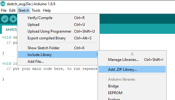
Next – open the Arduino IDE and select the Sketch > Include Library > Add .ZIP library option as shown below:

A dialog box will open – navigate to and select the zip file you downloaded earlier. After a moment or two the IDE will then install the library.

Please check that the library has been installed – to do this, select the Sketch > Include Library option in the IDE and scroll down the long menu until you see “ER-TFTM0.96-1” as shown below:

Once that has been successful, you can wire up your display.

Connecting the display to your Arduino

The display uses the SPI data bus for communication, and is a 3.3V board. You can use it with an Arduino or other 5V board as the logic is tolerant of higher voltages.

Arduino to Display

GND ----- GND (GND)
3.3V ---- Vcc (3.3V power supply)
D13 ----- SCL (SPI bus clock)
D11 ----- SDA (SPI bus data out from Arduino)
D10 ----- CS (SPI bus "Chip Select")
D9 ------ DC (Data instruction select pin)
D8 ------ RES (reset input)

If your Arduino has different pinouts than the Uno, locate the SPI pins for your board and modify as appropriate.

Demonstration sketch

Open a new sketch in the IDE, then copy and paste the following sketch into the IDE:

// https://pmdway.com/products/0-96-80-x-160-full-color-lcd-module
#include <UTFT.h>

// Declare which fonts we will be using
extern uint8_t SmallFont[];

// Initialize display
// Library only supports software SPI at this time
//NOTE: support  DUE , MEGA , UNO 
//SDI=11  SCL=13  /CS =10  /RST=8  D/C=9
UTFT myGLCD(ST7735S_4L_80160,11,13,10,8,9);    //LCD:  4Line  serial interface      SDI  SCL  /CS  /RST  D/C    NOTE:Only support  DUE   MEGA  UNO

// Declare which fonts we will be using
extern uint8_t BigFont[];

int color = 0;
word colorlist[] = {VGA_WHITE, VGA_BLACK, VGA_RED, VGA_BLUE, VGA_GREEN, VGA_FUCHSIA, VGA_YELLOW, VGA_AQUA};
int  bsize = 4;

void drawColorMarkerAndBrushSize(int col)
{
  myGLCD.setColor(VGA_BLACK);
  myGLCD.fillRect(25, 0, 31, 239);
  myGLCD.fillRect(myGLCD.getDisplayXSize()-31, 161, myGLCD.getDisplayXSize()-1, 191);
  myGLCD.setColor(VGA_WHITE);
  myGLCD.drawPixel(25, (col*30)+15);
  for (int i=1; i<7; i++)
    myGLCD.drawLine(25+i, ((col*30)+15)-i, 25+i, ((col*30)+15)+i);
  
  if (color==1)
    myGLCD.setColor(VGA_WHITE);
  else
    myGLCD.setColor(colorlist[col]);
  if (bsize==1)
    myGLCD.drawPixel(myGLCD.getDisplayXSize()-15, 177);
  else
    myGLCD.fillCircle(myGLCD.getDisplayXSize()-15, 177, bsize);
    
  myGLCD.setColor(colorlist[col]);
}
void setup()
{
  randomSeed(analogRead(0));
  
// Setup the LCD
  myGLCD.InitLCD();
  myGLCD.setFont(SmallFont);
}

void loop()
{
  int buf[158];
  int x, x2;
  int y, y2;
  int r;

// Clear the screen and draw the frame
  myGLCD.clrScr();

  myGLCD.setColor(255, 0, 0);
  myGLCD.fillRect(0, 0, 159, 13);
  myGLCD.setColor(64, 64, 64);
  myGLCD.fillRect(0, 114, 159, 127);
  myGLCD.setColor(255, 255, 255);
  myGLCD.setBackColor(255, 0, 0);
  myGLCD.print("pmdway.com.", CENTER, 1);
  myGLCD.setBackColor(64, 64, 64);
  myGLCD.setColor(255,255,0);
  myGLCD.print("pmdway.com", LEFT, 114);


  myGLCD.setColor(0, 0, 255);
  myGLCD.drawRect(0, 13, 159, 113);

// Draw crosshairs
  myGLCD.setColor(0, 0, 255);
  myGLCD.setBackColor(0, 0, 0);
  myGLCD.drawLine(79, 14, 79, 113);
  myGLCD.drawLine(1, 63, 158, 63);
  
 myGLCD.setColor(0, 0, 255);
 myGLCD.drawLine(0, 79, 159, 79);
 
  for (int i=9; i<150; i+=10)
    myGLCD.drawLine(i, 61, i, 65);
  for (int i=19; i<110; i+=10)
    myGLCD.drawLine(77, i, 81, i);
    

// Draw sin-, cos- and tan-lines  
  myGLCD.setColor(0,255,255);
  myGLCD.print("Sin", 5, 15);
  for (int i=1; i<158; i++)
  {
    myGLCD.drawPixel(i,63+(sin(((i*2.27)*3.14)/180)*40));
  }
  
  myGLCD.setColor(255,0,0);
  myGLCD.print("Cos", 5, 27);
  for (int i=1; i<158; i++)
  {
    myGLCD.drawPixel(i,63+(cos(((i*2.27)*3.14)/180)*40));
  }

  myGLCD.setColor(255,255,0);
  myGLCD.print("Tan", 5, 39);
  for (int i=1; i<158; i++)
  {
    myGLCD.drawPixel(i,63+(tan(((i*2.27)*3.14)/180)));
  }

  delay(2000);

  myGLCD.setColor(0,0,0);
  myGLCD.fillRect(1,14,158,113);
  myGLCD.setColor(0, 0, 255);
  myGLCD.setBackColor(0, 0, 0);
  myGLCD.drawLine(79, 14, 79, 113);
  myGLCD.drawLine(1, 63, 158, 63);

 myGLCD.setColor(0, 0, 255);
 myGLCD.drawLine(0, 79, 159, 79);  

// Draw a moving sinewave
  x=1;
  for (int i=1; i<(158*20); i++) 
  {
    x++;
    if (x==159)
      x=1;
    if (i>159)
    {
      if ((x==79)||(buf[x-1]==63))
        myGLCD.setColor(0,0,255);
      else
        myGLCD.setColor(0,0,0);
      myGLCD.drawPixel(x,buf[x-1]);
    }
    myGLCD.setColor(0,255,255);
    y=63+(sin(((i*2.5)*3.14)/180)*(40-(i / 100)));
    myGLCD.drawPixel(x,y);
    buf[x-1]=y;
  }

  delay(2000);
 
  myGLCD.setColor(0,0,0);
  myGLCD.fillRect(1,14,158,113);
  
 myGLCD.setColor(0, 0, 255);
 myGLCD.drawLine(0, 79, 159, 79);  

// Draw some filled rectangles
  for (int i=1; i<6; i++)
  {
    switch (i)
    {
      case 1:
        myGLCD.setColor(255,0,255);
        break;
      case 2:
        myGLCD.setColor(255,0,0);
        break;
      case 3:
        myGLCD.setColor(0,255,0);
        break;
      case 4:
        myGLCD.setColor(0,0,255);
        break;
      case 5:
        myGLCD.setColor(255,255,0);
        break;
    }
    myGLCD.fillRect(39+(i*10), 23+(i*10), 59+(i*10), 43+(i*10));
  }

  delay(2000);
  
  myGLCD.setColor(0,0,0);
  myGLCD.fillRect(1,14,158,113);
  myGLCD.setColor(0, 0, 255);
 myGLCD.drawLine(0, 79, 159, 79);   

// Draw some filled, rounded rectangles
  for (int i=1; i<6; i++)
  {
    switch (i)
    {
      case 1:
        myGLCD.setColor(255,0,255);
        break;
      case 2:
        myGLCD.setColor(255,0,0);
        break;
      case 3:
        myGLCD.setColor(0,255,0);
        break;
      case 4:
        myGLCD.setColor(0,0,255);
        break;
      case 5:
        myGLCD.setColor(255,255,0);
        break;
    }
    myGLCD.fillRoundRect(99-(i*10), 23+(i*10), 119-(i*10), 43+(i*10));
  }

  delay(2000);
  
  myGLCD.setColor(0,0,0);
  myGLCD.fillRect(1,14,158,113);

 myGLCD.setColor(0, 0, 255);
 myGLCD.drawLine(0, 79, 159, 79);  
// Draw some filled circles
  for (int i=1; i<6; i++)
  {
    switch (i)
    {
      case 1:
        myGLCD.setColor(255,0,255);
        break;
      case 2:
        myGLCD.setColor(255,0,0);
        break;
      case 3:
        myGLCD.setColor(0,255,0);
        break;
      case 4:
        myGLCD.setColor(0,0,255);
        break;
      case 5:
        myGLCD.setColor(255,255,0);
        break;
    }
    myGLCD.fillCircle(49+(i*10),33+(i*10), 15);
  }

  delay(2000);
    
  myGLCD.setColor(0,0,0);
  myGLCD.fillRect(1,14,158,113);
  
 myGLCD.setColor(0, 0, 255);
 myGLCD.drawLine(0, 79, 159, 79);    

// Draw some lines in a pattern
  myGLCD.setColor (255,0,0);
  for (int i=14; i<113; i+=5)
  {
    myGLCD.drawLine(1, i, (i*1.44)-10, 112);
  }
  myGLCD.setColor (255,0,0);
  for (int i=112; i>15; i-=5)
  {
    myGLCD.drawLine(158, i, (i*1.44)-12, 14);
  }
  myGLCD.setColor (0,255,255);
  for (int i=112; i>15; i-=5)
  {
    myGLCD.drawLine(1, i, 172-(i*1.44), 14);
  }
  myGLCD.setColor (0,255,255);
  for (int i=15; i<112; i+=5)
  {
    myGLCD.drawLine(158, i, 171-(i*1.44), 112);
  }

  delay(2000);
  
  myGLCD.setColor(0,0,0);
  myGLCD.fillRect(1,14,158,113);
  
 myGLCD.setColor(0, 0, 255);
 myGLCD.drawLine(0, 79, 159, 79);    

// Draw some random circles
  for (int i=0; i<100; i++)
  {
    myGLCD.setColor(random(255), random(255), random(255));
    x=22+random(116);
    y=35+random(57);
    r=random(20);
    myGLCD.drawCircle(x, y, r);
  }

  delay(2000);
  
  myGLCD.setColor(0,0,0);
  myGLCD.fillRect(1,14,158,113);
  
 myGLCD.setColor(0, 0, 255);
 myGLCD.drawLine(0, 79, 159, 79);    
  

// Draw some random rectangles
  for (int i=0; i<100; i++)
  {
    myGLCD.setColor(random(255), random(255), random(255));
    x=2+random(156);
    y=16+random(95);
    x2=2+random(156);
    y2=16+random(95);
    myGLCD.drawRect(x, y, x2, y2);
  }

  delay(2000);
  
  myGLCD.setColor(0,0,0);
  myGLCD.fillRect(1,14,158,113);
  
 myGLCD.setColor(0, 0, 255);
 myGLCD.drawLine(0, 79, 159, 79);    

// Draw some random rounded rectangles
  for (int i=0; i<100; i++)
  {
    myGLCD.setColor(random(255), random(255), random(255));
    x=2+random(156);
    y=16+random(95);
    x2=2+random(156);
    y2=16+random(95);
    myGLCD.drawRoundRect(x, y, x2, y2);
  }

  delay(2000);
  
  myGLCD.setColor(0,0,0);
  myGLCD.fillRect(1,14,158,113);
  
 myGLCD.setColor(0, 0, 255);
 myGLCD.drawLine(0, 79, 159, 79);  
 
  for (int i=0; i<100; i++)
  {
    myGLCD.setColor(random(255), random(255), random(255));
    x=2+random(156);
    y=16+random(95);
    x2=2+random(156);
    y2=16+random(95);
    myGLCD.drawLine(x, y, x2, y2);
  }

  delay(2000);
  
  myGLCD.setColor(0,0,0);
  myGLCD.fillRect(1,14,158,113);
  
 myGLCD.setColor(0, 0, 255);
 myGLCD.drawLine(0, 79, 159, 79);  
 
  for (int i=0; i<5000; i++)
  {
    myGLCD.setColor(random(255), random(255), random(255));
    myGLCD.drawPixel(2+random(156), 16+random(95));
  }

  delay(2000);

  myGLCD.fillScr(0, 0, 255);
  myGLCD.setColor(255, 0, 0);
  myGLCD.fillRoundRect(10, 17, 149, 72);
  
  myGLCD.setColor(255, 255, 255);
  myGLCD.setBackColor(255, 0, 0);
  myGLCD.print("That's it!", CENTER, 20);
  myGLCD.print("Restarting in a", CENTER, 45);
  myGLCD.print("few seconds...", CENTER, 57);
  
  myGLCD.setColor(0, 255, 0);
  myGLCD.setBackColor(0, 0, 255);
  myGLCD.print("Runtime: (msecs)", CENTER, 103);
  myGLCD.printNumI(millis(), CENTER, 115);

  delay (5000);   
}


Once you’re confident with the physical connection, upload the sketch. It should result with output as shown in the video below:

Now that you have succesfully run the demonstration sketch – where to from here?

The library used is based on the uTFT library by Henning Karlsen. You can find all the drawing and other commands in the user manual – so download the pdf and enjoy creating interesting displays.

This post brought to you by pmdway.com – everything for makers and electronics enthusiasts, with free delivery worldwide.

To keep up to date with new posts at tronixstuff.com, please subscribe to the mailing list in the box on the right, or follow us on twitter @tronixstuff.

Tronixstuff 29 Aug 09:15

Tutorial – Using the 0.96″ 128 x 64 Graphic I2C OLED Displays with Arduino

The purpose of this guide is to have an SSD1306-based OLED display successfully operating with your Arduino, so you can move forward and experiment and explore further types of operation with the display.

This includes installing the Arduino library, making a succesful board connection and running a demonstration sketch. So let’s get started!

Connecting the display to your Arduino

The display uses the I2C data bus for communication, and is a 5V and 3.3V-tolerant board.

Arduino Uno to Display

GND ---- GND (GND)
5V/3.3V- Vcc (power supply, can be 3.3V or 5V)
A5 ----- SCL (I2C bus clock)
A4 ----- SDA (I2C bus data)

I2C pinouts vary for other boards. Arduino Leonard uses D2/D3 for SDA and SCL or the separate pins to the left of D13. Arduino Mega uses D20/D21 for SDA and SCL. If you can’t find your I2C pins on other boards, ask your display supplier.

Installing the Arduino library

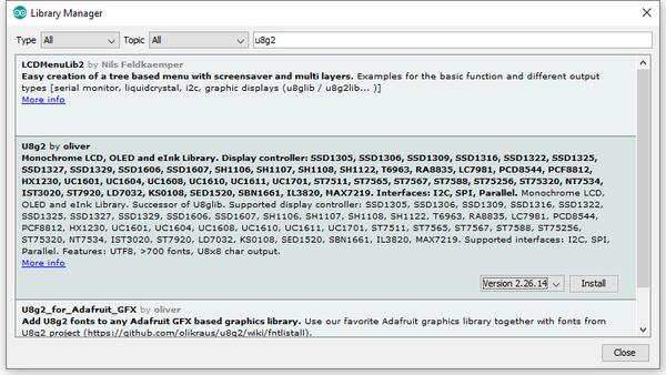
To install the library – simply open the Arduino IDE and select Manage Libraries… from the Tools menu. Enter “u8g2” in the search box, and after a moment it should appear in the results as shown in the image below. Click on the library then click “Install”:

After a moment the library will be installed and you can close that box.

Now it’s time to check everything necessary is working. Open a new sketch in the IDE, then copy and paste the following sketch into the IDE:

// Display > https://pmdway.com/products/0-96-128-64-graphic-oled-displays-i2c-or-spi-various-colors

#include <Arduino.h>
#include <U8x8lib.h>

#ifdef U8X8_HAVE_HW_SPI
#include <SPI.h>
#endif
#ifdef U8X8_HAVE_HW_I2C
#include <Wire.h>
#endif

  U8X8_SSD1306_128X64_NONAME_HW_I2C u8x8(/* reset=*/ U8X8_PIN_NONE);   

/*
  This example will probably not work with the SSD1606, because of the
  internal buffer swapping
*/

void setup(void)
{
  /* U8g2 Project: KS0108 Test Board */
  //pinMode(16, OUTPUT);
  //digitalWrite(16, 0);  

  /* U8g2 Project: Pax Instruments Shield: Enable Backlight */
  //pinMode(6, OUTPUT);
  //digitalWrite(6, 0); 

  u8x8.begin();
  //u8x8.setFlipMode(1);
}

void pre(void)
{
  u8x8.setFont(u8x8_font_amstrad_cpc_extended_f);    
  u8x8.clear();

  u8x8.inverse();
  u8x8.print(" U8x8 Library ");
  u8x8.setFont(u8x8_font_chroma48medium8_r);  
  u8x8.noInverse();
  u8x8.setCursor(0,1);
}

void draw_bar(uint8_t c, uint8_t is_inverse)
{ 
  uint8_t r;
  u8x8.setInverseFont(is_inverse);
  for( r = 0; r < u8x8.getRows(); r++ )
  {
    u8x8.setCursor(c, r);
    u8x8.print(" ");
  }
}

void draw_ascii_row(uint8_t r, int start)
{
  int a;
  uint8_t c;
  for( c = 0; c < u8x8.getCols(); c++ )
  {
    u8x8.setCursor(c,r);
    a = start + c;
    if ( a <= 255 )
      u8x8.write(a);
  }
}

void loop(void)
{
  int i;
  uint8_t c, r, d;
  pre();
  u8x8.print("github.com/");
  u8x8.setCursor(0,2);
  u8x8.print("olikraus/u8g2");
  delay(2000);
  u8x8.setCursor(0,3);
  u8x8.print("Tile size:");
  u8x8.print((int)u8x8.getCols());
  u8x8.print("x");
  u8x8.print((int)u8x8.getRows());
  
  delay(2000);
   
  pre();
  for( i = 19; i > 0; i-- )
  {
    u8x8.setCursor(3,2);
    u8x8.print(i);
    u8x8.print("  ");
    delay(150);
  }
  
  draw_bar(0, 1);
  for( c = 1; c < u8x8.getCols(); c++ )
  {
    draw_bar(c, 1);
    draw_bar(c-1, 0);
    delay(50);
  }
  draw_bar(u8x8.getCols()-1, 0);

  pre();
  u8x8.setFont(u8x8_font_amstrad_cpc_extended_f); 
  for( d = 0; d < 8; d ++ )
  {
    for( r = 1; r < u8x8.getRows(); r++ )
    {
      draw_ascii_row(r, (r-1+d)*u8x8.getCols() + 32);
    }
    delay(400);
  }

  draw_bar(u8x8.getCols()-1, 1);
  for( c = u8x8.getCols()-1; c > 0; c--)
  {
    draw_bar(c-1, 1);
    draw_bar(c, 0);
    delay(50);
  }
  draw_bar(0, 0);

  pre();
  u8x8.drawString(0, 2, "Small");
  u8x8.draw2x2String(0, 5, "Scale Up");
  delay(3000);

  pre();
  u8x8.drawString(0, 2, "Small");
  u8x8.setFont(u8x8_font_px437wyse700b_2x2_r);
  u8x8.drawString(0, 5, "2x2 Font");
  delay(3000);

  pre();
  u8x8.drawString(0, 1, "3x6 Font");
  u8x8.setFont(u8x8_font_inb33_3x6_n);
  for(i = 0; i < 100; i++ )
  {
    u8x8.setCursor(0, 2);
    u8x8.print(i);      // Arduino Print function
    delay(10);
  }
  for(i = 0; i < 100; i++ )
  {
    u8x8.drawString(0, 2, u8x8_u16toa(i, 5)); // U8g2 Build-In functions
    delay(10);    
  }

  pre();
  u8x8.drawString(0, 2, "Weather");
  u8x8.setFont(u8x8_font_open_iconic_weather_4x4);
  for(c = 0; c < 6; c++ )
  {
    u8x8.drawGlyph(0, 4, '@'+c);
    delay(300);
  }
  

  pre();
  u8x8.print("print \\n\n");
  delay(500);
  u8x8.println("println");
  delay(500);
  u8x8.println("done");
  delay(1500);

  pre();
  u8x8.fillDisplay();
  for( r = 0; r < u8x8.getRows(); r++ )
  {
    u8x8.clearLine(r);
    delay(100);
  }
  delay(1000);
}

Your display should go through the demonstration of various things as shown in the video below:

If the display did not work – you may need to manually set the I2C bus address. To do this, wire up your OLED then run this sketch (open the serial monitor for results). It’s an I2C scanner tool that will return the I2C bus display. 

Then use the following line in void setup():

u8x8.setI2CAddress(address)

Replace u8x8 with your display reference, and address with the I2C bus address (for example. 0x17).

Moving on…

By now you have an idea of what is possible with these great-value displays.

Now your display is connected and working, it’s time to delve deeper into the library and the various modes of operations. There are three, and they are described in the library documentation – click here to review them

Whenever you use one of the three modes mentioned above, you need to use one of the following constructor lines:

U8G2_SSD1306_128X64_NONAME_F_HW_I2C u8g2(U8G2_R0, /* reset=*/ U8X8_PIN_NONE); // full buffer mode

U8X8_SSD1306_128X64_NONAME_HW_I2C u8x8(/* reset=*/ U8X8_PIN_NONE); // 8x8 character mode

U8G2_SSD1306_128X64_NONAME_1_HW_I2C u8g2(U8G2_R0, /* reset=*/ U8X8_PIN_NONE); // page buffer mode

Match the mode you wish to use with one of the constructors above. For example, in the demonstration sketch you ran earlier, we used the 8×8 character mode constructor in line 14.

Where to from here?

Now it’s time for you to explore the library reference guide which explains all the various functions available to create text and graphics on the display, as well as the fonts and so on. These can all be found on the right-hand side of the driver wiki page.

This post brought to you by pmdway.com – everything for makers and electronics enthusiasts, with free delivery worldwide.

To keep up to date with new posts at tronixstuff.com, please subscribe to the mailing list in the box on the right, or follow us on twitter @tronixstuff.

Tronixstuff 29 Aug 08:38

First Look – Arduino M0 Pro with 32 bit ARM Cortex M0

Here at tronixstuff we keep an open mind with regards to new hardware, and in this spirit we have the following “first look” of the new Arduino M0 Pro (previously called the Arduino Zero) from Arduino SRL. If the term Arduino SRL is new to you – click here to learn more.

This is the second Arduino-branded board that takes the leap from 8-bit to 32-bit microcontrollers (with the Due being the first), and according to Arduino SRL offers a lot of promise:

With the new Arduino M0 pro board, the more creative individual will have the potential to create one’s most imaginative and new ideas for IoT devices, wearable technologies, high tech automation, wild robotics and other not yet thinkable adventures in the world of makers.

The Arduino M0 pro represents a simple, yet powerful, 32-bit extension of the Arduino UNO platform. The board is powered by Atmel’s SAMD21 MCU, featuring a 32-bit ARM Cortex® M0 core.

With the addition of the M0 board, the Arduino family becomes larger with a new member providing increased performance.

The power of its Atmel’s core gives this board an upgraded flexibility and boosts the scope of projects one can think of and make; moreover, it makes the M0 Pro the ideal educational tool for learning about 32-bit application development.
Atmel’s Embedded Debugger (EDBG), integrated in the board, provides a full debug interface with no need for additional hardware, making debugging much easier. EDBG additionally supports a virtual COM port for device programming and traditional Arduino boot loader functionality uses.

Lots of buzzwords in there, so let’s push that aside and first consider the specifications:

Microcontroller – ATSAMD21G18, 48pins LQFP – the “main” microcontroller
EDBG Microcontroller – AT32UC3A4256, 100pins VFBGA
Operating Voltage – 3.3 V
DC Input Voltage (recommended) – 6-15 V
DC Input Voltage (limits) – 4.5-20 V
Digital I/O Pins – 14, with 12 PWM and UART
Analogue Input Pins – 6, 12-bit ADC channels
Analogue Output Pins – 1, 10-bit DAC
DC Current per I/O Pin – 7 mA
Flash Memory – 256 KB
SRAM – 32 KB
Clock Speed – 48 MHz

Lots of good stuff there – increased clock speed, increased flash memory (sketch space) and SRAM (working memory). No EEPROM however you can emulate one.

Note that the M0 Pro is a 3.3V board – and also the DC current per I/O pin is only 7 mA. Once again the user will need to carefully consider their use of external circuitry and shields to ensure compatibility (as the “classic” Arduino boards are 5V and can happily source/sink much more current per I/O pin).

The ADC (analogue-to-digital) converters have an increased resolution – 12-bit… and the addition of a true DAC (digital-to-analogue) converter allows for a true variable voltage output. This could be useful for sound generation or other effects. You can pore over the complete details including board schematics from the arduino.org website.

Moving on, let’s have a look around the Arduino M0 Pro board itself:

You can’t miss the sticker asking you to download the IDE – as Arduino SRL have forked up the Arduino IDE and run off with it. Click here to download. Upon removing the sticker you have:

Note the connector for the JTAG interface which works in conjunction with Atmel Studio software for debugging. You can also use the USB connection which connects to the EDBG microcontroller (example). When Atmel offers a native MacOS version we’ll investigate that further. SPI isn’t D10~D13 as per the older boards, instead it is accessed via the six pins on the right-hand side of the board. Turning the M0 Pro over doesn’t reveal any surprises:

And like the Due there are two USB ports:

A Programming USB port for uploading sketches through the Arduino IDE and “normal” use, along with a native USB port for direct connection to the main microcontroller’s serial connection. For “regular” Arduino IDE use, you can stick with the Programming port as usual.

So let’s try out the M0 Pro. We’ve downloaded the arduino.org IDE (which can co-exist with the arduino.cc IDE). Drivers are included with the IDE for Windows users, so the board should be plug and play. Note that if you need to reflash the Arduino bootloader – Atmel Studio is required. Moving on – within the Arduino IDE you need to set the board type to “Arduino M0 Pro (Programming Port)”:

… and the Programmer to “M0 Pro Programming Port”:

… both of these options are found in the Tools menu. When using these faster boards we like to run a simple speed test that calculates Newton Approximation for pi using an infinite series, written by Steve Curd from the Arduino forum. You can download the sketch to try yourself.

In previous tests the Arduino Mega2560 completed the test in 5765 ms, and the Arduino Due crushed it in 690 ms. As you can see below the M0 Pro needed 1950 ms for the test:

Not bad at all compared to a Mega. Thus the M0 Pro offers you a neat speed bump in an Uno-compatible form-factor. At this point those of you who enjoy making your own boards and dealing with surface-mount components have an advantage – the Atmel ATSAMD21G18 is available in TQFP package for under US$6… so you could cook up your own high-performance boards. Example.

At this point I’m curious about the onboard 10-bit DAC that’s connected to pin A0, so I connected the DSO to A0 and GND, and uploaded the following sketch:

void setup() 
{
  pinMode(A0,OUTPUT);
}

void loop() 
{
  for (int i=0; i<1024; i++)
  {
    analogWrite(A0,i);
  }
  for (int i=1023; i>=0; --i)
  {
    analogWrite(A0,i);
  }
}

… which resulted with the following neat triangle waveform:

… and here it is with the statistics option:

With a frequency of 108.7 Hz there’s a lot of CPU overhead – no doubt controlling the MCU without the Arduino abstraction will result with increased performance. Finally – for some other interesting examples and “how to” guides for the M0 Pro, visit the Arduino labs page for this board.

Conclusion for now

There are many pros and cons with the Arduino M0 Pro. It is not the best “all round” or beginner’s board due to the limitations of the hardware GPIO. There’s the DAC which could be useful for creating Arduino-controlled power supplies – and plenty of PWM outputs… but don’t directly connect servos to them. However if you can live with the current limits – and need a faster clock speed with an Arduino Uno-compatible board type – then the M0 Pro is an option for you.

Furthermore the M0 Pro offers an interesting bridge into the world of 32-bit microcontrollers, and no doubt the true performance of the MCU can be unlocked by moving away from the Arduino IDE and using Atmel Studio. If you have any questions for the arduino.org team about the Arduino M0 Pro ask in their support forum.

And if you would like your own Arduino M0 Pro – tronixlabs.com is offering a 10% discount off this new board until the end of November 2015. Enter the coupon code “tronixstuff” in the shopping cart page to activate the discount**. tronixlabs.com – which along with being Australia’s #1 Adafruit distributor, also offers a growing range and great value for supported hobbyist electronics from Altronics, DFRobot, Freetronics, Jaycar, Seeedstudio and much much more.

As always, have fun and keep checking into tronixstuff.com. Why not follow things on twitterGoogle+, subscribe  for email updates or RSS using the links on the right-hand column, or join our forum – dedicated to the projects and related items on this website.

** discount not available in conjunction with any other offer, and not valid for CCHS/MELBPC deliveries or pickup orders. 

The post First Look – Arduino M0 Pro with 32 bit ARM Cortex M0 appeared first on tronixstuff.

Control your Arduino over the Internet using Blynk

Introduction

There are many ways of remotely-controlling your Arduino or compatible hardware over the Internet. Some are more complex than others, which can be a good thing or a bad thing depending on your level of expertise. Lately we’ve become more interested in this topic and have come across Blynk, which appeared to be a simple solution – and thus the topic of our review.

What is Blynk?

From their website: “Blynk is a Platform with iOS and Android apps to control Arduino, Raspberry Pi and the likes over the Internet. It’s a digital dashboard where you can build a graphic interface for your project by simply dragging and dropping widgets. 

It’s really simple to set everything up and you’ll start tinkering in less than 5 mins. Blynk is not tied to some specific board or shield. Instead, it’s supporting hardware of your choice. Whether your Arduino or Raspberry Pi is linked to the Internet over Wi-Fi, Ethernet or this new ESP8266 chip, Blynk will get you online and ready for the Internet Of Your Things.” Here is the original launch video:


Blynk started off as an idea, and raised initial funding through Kickstarter – which was successful and the system has now launched. Blynk comprises of an app on your smartphone (Android or iOS) inside which you can add widgets (controls) to send commands back to your development board (Arduino etc.).

For example, you can add a switch to turn a digital output on or off. Furthermore, data from sensors connected to the development board can be send back to the smartphone. The data passes through the Blynk Cloud server, or you can download and run your own server on your own hardware and infrastructure.

How much does it cost?

Right now (September 2015) the Blynk system is free. We downloaded the app and experimented without charge. We believe that over time there will be payment required for various functions, however you can try it out now to see if Blynk suits your needs then run with it later or experiment with other platforms.

Getting Started

Well enough talk, let’s try Blynk out. Our hardware is an Android smartphone (the awesome new Oppo R7+) for control, and a Freetronics EtherTen connected to our office modem/router:

You can also use other Arduino+Ethernet combinations, such as an Arduino Uno with an Ethernet shield. First you need to download the app for your phone – click here for the links. Then from the same page, download the Arduino library – and install it like you would any other Arduino library.

For our first example, we’ll use an LED connected to digital pin 7 (via a 560 ohm resistor) shown above. Now it’s time to set up the Blynk app. When you run the app for the first time, you need to sign in – so enter an email address and password:

Then click the “+” at the top-right of the display to create a new project, and you should see the following screen:

You can name your project, select the target hardware (Arduino Uno) – then click “E-mail” to send that auth token to yourself – you will need it in a moment. Then click “Create” to enter the main app design screen. Next, press “+” again to get the “Widget Box” menu as shown below, then press “Button”:

This will place a simple button on your screen:

Press the button to open its’ settings menu:

From this screen you can name your button, and also determine whether it will be “momentary” (i.e., only on when you press the button) – or operate as a switch (push on… push off…). Furthermore you need to select which physical Arduino pin the button will control – so press “PIN”, which brings up the scrolling menu as shown below:

We set ours to D7 then pressed “Continue”. Now the app is complete. Now head back to your computer, open the Arduino IDE, and load the “Arduino_Ethernet” sketch included with the library:

Then scroll down to line 30 and enter the auth key that was sent to you via email:

Save then upload the sketch to your Arduino. Now head back to your smartphone, and click the “Play” (looks like a triangle pointing right) button. After a moment the app will connect to the Blynk server… the Arduino will also be connected to the server – and you can press the button on the screen to control the LED.

And that’s it – remote control really is that easy. We’ve run through the process in the following short video:

Now what else can we control? How about some IKEA LED strips from our last article. Easy… that consisted of three digital outputs, with PWM. The app resembles the following:

… and watch the video below to see it in action:

Monitoring data from an Arduino via Blynk

Data can also travel in the other direction – from your Arduino over the Internet to your smartphone. At the time of writing this (September 2015) you can monitor the status of analogue and digital pins, and widgets can be added in the app to do just that. They can display the value returned from each ADC, which falls between zero and 1023 – and display the values in various forms – for example:

The bandwidth required for this is just under 2 K/s, as you can see from the top of the image above. You can see this in action through the video below:

Conclusion

We have only scratched the surface of what is possible with Blynk – which is an impressive, approachable and usable “Internet of Things” platform. Considering that you can get an inexpensive Android smartphone or tablet for under AU$50, the overall cost of using Blynk is excellent and well worth consideration, even just to test out the “Internet of Things” buzz yourself. So to get started head over to the Blynk site.

And finally a plug for our own store – tronixlabs.com – which along with being Australia’s #1 Adafruit distributor, also offers a growing range and Australia’s best value for supported hobbyist electronics from DFRobot, Freetronics, Seeedstudio and much much more.

As always, have fun and keep checking into tronixstuff.com. Why not follow things on twitterGoogle+, subscribe  for email updates or RSS using the links on the right-hand column, or join our forum – dedicated to the projects and related items on this website.

The post Control your Arduino over the Internet using Blynk appeared first on tronixstuff.

Tronixstuff 20 Sep 09:30

Control your Arduino over the Internet using Blynk

Introduction

There are many ways of remotely-controlling your Arduino or compatible hardware over the Internet. Some are more complex than others, which can be a good thing or a bad thing depending on your level of expertise. Lately we’ve become more interested in this topic and have come across Blynk, which appeared to be a simple solution – and thus the topic of our review.

What is Blynk?

From their website: “Blynk is a Platform with iOS and Android apps to control Arduino, Raspberry Pi and the likes over the Internet. It’s a digital dashboard where you can build a graphic interface for your project by simply dragging and dropping widgets. 

It’s really simple to set everything up and you’ll start tinkering in less than 5 mins. Blynk is not tied to some specific board or shield. Instead, it’s supporting hardware of your choice. Whether your Arduino or Raspberry Pi is linked to the Internet over Wi-Fi, Ethernet or this new ESP8266 chip, Blynk will get you online and ready for the Internet Of Your Things.” Here is the original launch video:

Blynk started off as an idea, and raised initial funding through Kickstarter – which was successful and the system has now launched. Blynk comprises of an app on your smartphone (Android or iOS) inside which you can add widgets (controls) to send commands back to your development board (Arduino etc.).

For example, you can add a switch to turn a digital output on or off. Furthermore, data from sensors connected to the development board can be send back to the smartphone. The data passes through the Blynk Cloud server, or you can download and run your own server on your own hardware and infrastructure.

How much does it cost?

Right now (September 2015) the Blynk system is free. We downloaded the app and experimented without charge. We believe that over time there will be payment required for various functions, however you can try it out now to see if Blynk suits your needs then run with it later or experiment with other platforms.

Getting Started

Well enough talk, let’s try Blynk out. Our hardware is an Android smartphone (the awesome new Oppo R7+) for control, and a Freetronics EtherTen connected to our office modem/router:

You can also use other Arduino+Ethernet combinations, such as an Arduino Uno with an Ethernet shield. First you need to download the app for your phone – click here for the links. Then from the same page, download the Arduino library – and install it like you would any other Arduino library.

For our first example, we’ll use an LED connected to digital pin 7 (via a 560 ohm resistor) shown above. Now it’s time to set up the Blynk app. When you run the app for the first time, you need to sign in – so enter an email address and password:

Then click the “+” at the top-right of the display to create a new project, and you should see the following screen:

You can name your project, select the target hardware (Arduino Uno) – then click “E-mail” to send that auth token to yourself – you will need it in a moment. Then click “Create” to enter the main app design screen. Next, press “+” again to get the “Widget Box” menu as shown below, then press “Button”:

This will place a simple button on your screen:

Press the button to open its’ settings menu:

From this screen you can name your button, and also determine whether it will be “momentary” (i.e., only on when you press the button) – or operate as a switch (push on… push off…). Furthermore you need to select which physical Arduino pin the button will control – so press “PIN”, which brings up the scrolling menu as shown below:

We set ours to D7 then pressed “Continue”. Now the app is complete. Now head back to your computer, open the Arduino IDE, and load the “Arduino_Ethernet” sketch included with the library:

Then scroll down to line 30 and enter the auth key that was sent to you via email:

Save then upload the sketch to your Arduino. Now head back to your smartphone, and click the “Play” (looks like a triangle pointing right) button. After a moment the app will connect to the Blynk server… the Arduino will also be connected to the server – and you can press the button on the screen to control the LED.

And that’s it – remote control really is that easy. We’ve run through the process in the following short video:

Now what else can we control? How about some IKEA LED strips from our last article. Easy… that consisted of three digital outputs, with PWM. The app resembles the following:

… and watch the video below to see it in action:

Monitoring data from an Arduino via Blynk

Data can also travel in the other direction – from your Arduino over the Internet to your smartphone. At the time of writing this (September 2015) you can monitor the status of analogue and digital pins, and widgets can be added in the app to do just that. They can display the value returned from each ADC, which falls between zero and 1023 – and display the values in various forms – for example:

The bandwidth required for this is just under 2 K/s, as you can see from the top of the image above. You can see this in action through the video below:

Conclusion

We have only scratched the surface of what is possible with Blynk – which is an impressive, approachable and usable “Internet of Things” platform. Considering that you can get an inexpensive Android smartphone or tablet for under AU$50, the overall cost of using Blynk is excellent and well worth consideration, even just to test out the “Internet of Things” buzz yourself. So to get started head over to the Blynk site.

Tronixstuff 20 Sep 09:30

Experimenting with Arduino and IKEA DIODER LED Strips

Introduction

A few weeks ago I found a DIODER LED strip set from a long-ago trek to IKEA, and considered that something could be done with it.  So in this article you can see how easy it is to control the LEDs using an Arduino or compatible board with ease… opening it up to all sorts of possibilities.

This is not the most original project – however things have been pretty quiet around here, so I thought it was time to share something new with you. Furthermore the DIODER control PCB has changed, so this will be relevant to new purchases. Nevertheless, let’s get on with it.

So what is DIODER anyhow? 

As you can see in the image below, the DIODER pack includes four RGB LED units each with nine RGB LEDs per unit. A controller box allows power and colour choice, a distribution box connects between the controller box and the LED strips, and the whole thing is powered by a 12V DC plugpack:

The following is a quick video showing the DIODER in action as devised by IKEA:


Thankfully the plugpack keeps us away from mains voltages, and includes a long detachable cable which connects to the LED strip distribution box. The first thought was to investigate the controller, and you can open it with a standard screwdriver. Carefully pry away the long-side, as two clips on each side hold it together…


… which reveals the PCB. Nothing too exciting here – you can see the potentiometer used for changing the lighting effects, power and range buttons and so on:

Our DIODER has the updated PCB with the Chinese market microcontroller. If you have an older DIODER with a Microchip PIC – you can reprogram it yourself.

The following three MOSFETs are used to control the current to each of the red, green and blue LED circuits. These will be the key to controlling the DIODER’s strips – but are way too small for me to solder to. The original plan was to have an Arduino’s PWM outputs tap into the MOSFET’s gates – but instead I will use external MOSFETs.

So what’s a MOSFET?

In the past you may have used a transistor to switch higher current from an Arduino, however a MOSFET is a better solution for this function. The can control large voltages and high currents without any effort. We will use N-channel MOSFETs, which have three pins – Source, Drain and Gate. When the Gate is HIGH, current will flow into the Drain and out of the Source:

A simplistic explanation is that it can be used like a button – and when wiring your own N-MOSFET a 10k resistor should be used between Gate and Drain to keep the Gate low when the Arduino output is set to LOW (just like de-bouncing a button). To learn more about MOSFETS – get yourself a copy of “The Art of Electronics“. It is worth every cent.

However being somewhat time poor (lazy?), I have instead used a Freetronics NDrive Shield for Arduino – which contains six N-MOSFETs all on one convenient shield  – with each MOSFET’s Gate pin connected to an Arduino PWM output.

So let’s head back to the LED strips for a moment, in order to determine how the LEDs are wired in the strip. Thanks to the manufacturer – the PCB has the markings as shown below:

They’re 12V LEDs in a common-anode configuration. How much current do they draw? Depends on how many strips you have connected together…

For the curious I measured each colour at each length, with the results in the following table:

So all four strips turned on, with all colours on – the strips will draw around 165 mA of current at 12V. Those blue LEDs are certainly thirsty.

Moving on, the next step is to connect the strips to the MOSFET shield. This is easy thanks to the cable included in the DIODER pack, just chop the white connector off as shown below:

By connecting an LED strip to the other end of the cable you can then determine which wire is common, and which are the cathodes for red, green and blue.

The plugpack included with the DIODER pack can be used to power the entire project, so you will need cut the DC plug (the plug that connects into the DIODER’s distribution box) off the lead, and use a multimeter to determine which wire is negative, and which is positive.

Connect the negative wire to the GND terminal on the shield, and the positive wire to the Vin terminal.  Then…

  • the red LED wire to the D3 terminal,
  • the green LED wire to the D9 terminal,
  • and the blue LED wire to the D10 terminal.

Finally, connect the 12V LED wire (anode) into the Vin terminal. Now double-check your wiring. Then check it again.

Testing

Now to run a test sketch to show the LED strip can easily be controlled. We’ll turn each colour on and off using PWM (Pulse-Width Modulation) – a neat way to control the brightness of each colour. The following sketch will pulse each colour in turn, and there’s also a blink function you can use.

// Controlling IKEA DIODER LED strips with Arduino and Freetronics NDRIVE N-MOSFET shield
// CC by-sa-nc John Boxall 2015 - tronixstuff.com 
// Components from tronixlabs.com

#define red 3
#define green 9
#define blue 10
#define delaya 2

void setup() 
{
  pinMode(red, OUTPUT);
  pinMode(green, OUTPUT);
  pinMode(blue, OUTPUT);
}

void blinkRGB()
{
  digitalWrite(red, HIGH);
  delay(1000);
  digitalWrite(red, LOW);
  digitalWrite(green, HIGH);
  delay(1000);
  digitalWrite(green, LOW);
  digitalWrite(blue, HIGH);
  delay(1000);
  digitalWrite(blue, LOW);
}

void pulseRed()
{
  for (int i=0; i<256; i++)
  {
    analogWrite(red,i);
    delay(delaya);
  }
  for (int i=255; i>=0; --i)
  {
    analogWrite(red,i);
    delay(delaya);
  }
}

void pulseGreen()
{
  for (int i=0; i<256; i++)
  {
    analogWrite(green,i);
    delay(delaya);
  }
  for (int i=255; i>=0; --i)
  {
    analogWrite(green,i);
    delay(delaya);
  }
}

void pulseBlue()
{
  for (int i=0; i<256; i++)
  {
    analogWrite(blue,i);
    delay(delaya);
  }
  for (int i=255; i>=0; --i)
  {
    analogWrite(blue,i);
    delay(delaya);
  }
}

void loop()
{
  pulseRed();
  pulseGreen();
  pulseBlue();
}

Success. And for the non-believers, watch the following video:

Better LED control

As always, there’s a better way of doing things and one example of LED control is the awesome FASTLED library by Daniel Garcia and others. Go and download it now – https://github.com/FastLED/FastLED. Apart from our simple LEDS, the FASTLED library is also great with WS2812B/Adafruit NeoPixels and others.

One excellent demonstration included with the library is the AnalogOutput sketch, which I have supplied below to work with our example hardware:

#include <FastLED.h>

// Example showing how to use FastLED color functions
// even when you're NOT using a "pixel-addressible" smart LED strip.
//
// This example is designed to control an "analog" RGB LED strip
// (or a single RGB LED) being driven by Arduino PWM output pins.
// So this code never calls FastLED.addLEDs() or FastLED.show().
//
// This example illustrates one way you can use just the portions 
// of FastLED that you need.  In this case, this code uses just the
// fast HSV color conversion code.
// 
// In this example, the RGB values are output on three separate
// 'analog' PWM pins, one for red, one for green, and one for blue.
 
#define REDPIN   3
#define GREENPIN 9
#define BLUEPIN  10

// showAnalogRGB: this is like FastLED.show(), but outputs on 
// analog PWM output pins instead of sending data to an intelligent,
// pixel-addressable LED strip.
// 
// This function takes the incoming RGB values and outputs the values
// on three analog PWM output pins to the r, g, and b values respectively.
void showAnalogRGB( const CRGB& rgb)
{
  analogWrite(REDPIN,   rgb.r );
  analogWrite(GREENPIN, rgb.g );
  analogWrite(BLUEPIN,  rgb.b );
}


// colorBars: flashes Red, then Green, then Blue, then Black.
// Helpful for diagnosing if you've mis-wired which is which.
void colorBars()
{
  showAnalogRGB( CRGB::Red );   delay(500);
  showAnalogRGB( CRGB::Green ); delay(500);
  showAnalogRGB( CRGB::Blue );  delay(500);
  showAnalogRGB( CRGB::Black ); delay(500);
}

void loop() 
{
  static uint8_t hue;
  hue = hue + 1;
  // Use FastLED automatic HSV->RGB conversion
  showAnalogRGB( CHSV( hue, 255, 255) );
  
  delay(20);
}


void setup() {
  pinMode(REDPIN,   OUTPUT);
  pinMode(GREENPIN, OUTPUT);
  pinMode(BLUEPIN,  OUTPUT);

  // Flash the "hello" color sequence: R, G, B, black.
  colorBars();
}

You can see this in action through the following video:

Control using a mobile phone?

Yes – click here to learn how.

Conclusion

So if you have some IKEA LED strips, or anything else that requires more current than an Arduino’s output pin can offer – you can use MOSFETs to take over the current control and have fun. And finally a plug for my own store – tronixlabs.com – offering a growing range and Australia’s best value for supported hobbyist electronics from adafruit, DFRobot, Freetronics, Seeed Studio and much much more.

As always, have fun and keep checking into tronixstuff.com. Why not follow things on twitterGoogle+, subscribe  for email updates or RSS using the links on the right-hand column, or join our forum – dedicated to the projects and related items on this website.