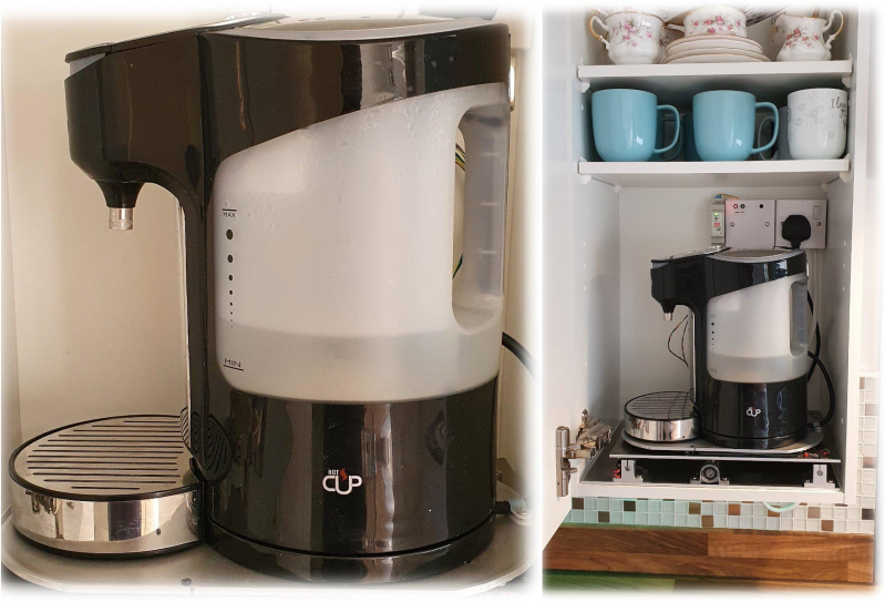
How far would you go for your cup of tea? [samsungite]’s missus doesn’t like clutter on her countertops, so away the one-cup kettle would go back into the cupboard for next time while the tea steeped. As long as there’s room for it in there, why not install it there permanently? That’s the idea behind RoboTray, which would only be cooler if it could be plumbed somehow.
RoboTray went through a few iterations, most importantly the switch from 6mm MDF to 4 mm aluminum plate. A transformer acts as a current sensor, and when the kettle is powered on, the tray first advances forward 7 cm using a 12 VDC motor and an Arduino. Then it pivots 90° on a lazy Susan driven by another 12 VDC motor. The kettle is smart enough to turn itself off when finished, and the Arduino senses this and reverses all the steps after a ten-second warning period. Check it out in action after the break.
If [samsungite] has any more Arduinos lying around, he might appreciate this tea inventory tracker.
Traditionally, the useless machine is a simple one that invites passersby to switch it on. When they do, the machine somehow, some way, turns itself off; usually with a finger or finger-like object that comes out from the box in what feels like an annoyed fashion. Honestly, that’s probably part of what drives people to turn them on over and over again.
What’s really happening is that an Arduino is getting a signal from the toggle switch, and is then rotating it on a ball bearing with a stepper motor driven through an H-bridge.
It shouldn’t be too hard to make one of these yourself, given that [Bart] has provided the schematic and STLs. If we weren’t living in such touchy times, we might suggest building one of these into your Halloween candy distribution scheme somehow. Sell the switch as one that turns on a candy dispenser, and then actually dispense it after three or five tries.
We’re not going to question why [Absorber Of Light] needs to cut a bazillion little fragments of aluminum stock. We assume his reasoning is sound, so all we’re interested in is the automated chop saw he built to make the job less tedious, and potentially less finger-choppy.
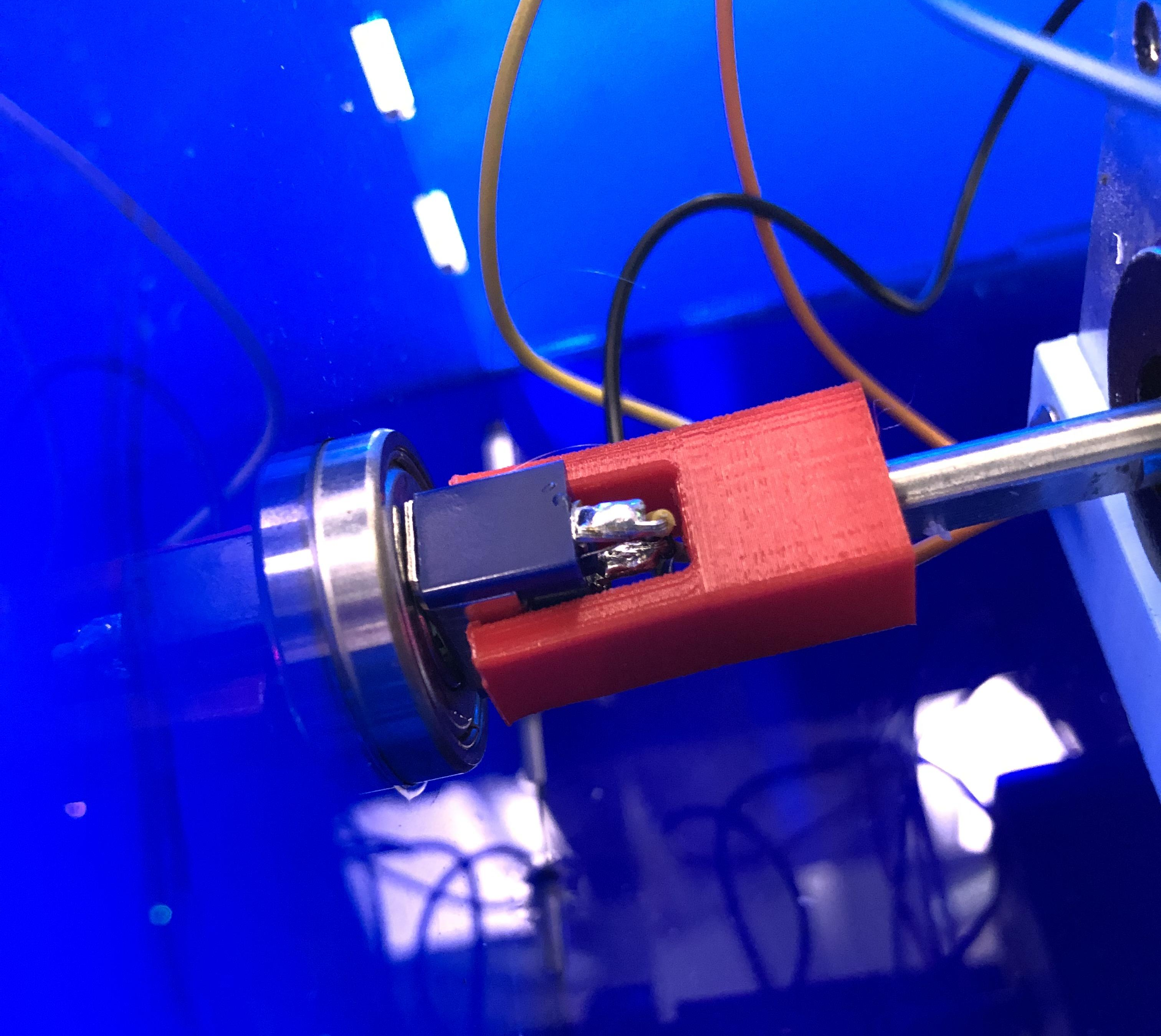
There are probably many ways to go about this job, but [Absorber] leaves few clues as to why he chose this particular setup. Whatever the reason, the build looks like fun, with a long, stepper-driven threaded rod pushing a follower down a track to a standard chop saw. The aluminum stock rides in the track and gets pushed out a set amount before being lopped off cleanly as the running saw is lowered by a linear actuator. The cycle then repeats until the stock is gone.
An Arduino controls the stock-advance stepper in the usual way, but the control method for the linear actuator is somewhat unconventional. A second stepper motor has two cams offset by 180° on the shaft. The cams actuate four microswitches which are set up in an H-bridge configuration. The stepper swivels back and forth to run the linear actuator first in one direction then the other, with a neutral position in between. It’s an interesting approach using mechanical rather than the typical optical isolation. Check it out in action in the video below.
We’ll admit to some curiosity as to the use of the coupons this rig produces, so maybe we’ll get lucky with some details from [Absorber Of Light] in the comment section. After all, we knew exactly what the brass tubes being cut by the similar “Auto Mega Cut-O-Matic” were being used for.
It’s ridiculously easy to lay hands on a cheap DC-to-AC inverter these days. They’re in just about every discount or variety store and let you magically plug in mains powered devices where no outlets exist. Need 120- or 240-VAC in your car? No problem – a little unit that plugs into the lighter socket is available for a few bucks.
So are these commodity items worth building yourself? Probably not as [GreatScott!] explains, but learning how they work and what their limitations are will probably help your designs. The cheapest and most common inverters have modified square wave outputs, which yield a waveform that’s good enough for most electronics and avoids the extra expense of producing a pure sinusoidal output. He explains that the waveform is just a square wave with a slight delay at the zero-crossing points to achieve the stepped pattern, and shows a simple H-bridge circuit to produce it. He chose to drive the output section with an Arduino, to easily produce the zero-crossing delay. He uses this low-voltage inverter to demonstrate how much more complicated the design needs to get to overcome the spikes caused by inductive loads and the lack of feedback from the output.
Bottom line: it’s nice to know how inverters work, but some things are better bought than built. That won’t stop people from building them, of course, and knowing what you’re doing in this field has been worth big bucks in the past.
Imagine trying to make a ball-shaped robot that rolls in any direction but with a head that stays on. When I saw the BB-8 droid doing just that in the first Star Wars: The Force Awakens trailer, it was an interesting engineering challenge that I couldn’t resist. All the details for how I made it would fill a book, so here are the highlights: the problems I ran into, how I solved them and what I learned.
The Design Criteria: Portable and Inexpensive
Carrying BB-8
I had two design criteria in mind. The first was to keep it low-cost. Some spend $1000 to $1500 on their BB-8s. I wanted to spend as little as I could, so as many parts as possible had to come from my existing stock and from online classifieds and thrift stores. Not counting the parts that were discarded along the way, the cost came in just shy of $300.
The second design criteria was to make it portable. It had to be something I could take on the bus or carry while walking a reasonable distance (I once carried it twenty-five minutes to a nearby school).
Both of these criteria meant that it had to be smaller than full size. A full size ball is 20″ in diameter. Mine has a 12″ ball which makes it 3/5 scale. Also, the larger it is, the more powerful and costly the motors, batteries, motor controllers, magnets, and so on.
Version One: Quick And Easy
First I tried a minimalist approach. For the ball, I found my 12″ cardboard globe on kijiji.ca. I bought an RC toy truck at a yard sale and attached a pole to it for holding magnets near the top of the globe. I then made a head with corresponding magnets under it. The head magnets attract to the pole magnets, keeping the head on. Meanwhile, the truck rolling inside the ball makes the ball move.
Making the ball roll around was easy. Making it roll around while keeping the head on was very hard. The magnets at the top of the pole attract the magnets under the head, pulling them down hard onto the surface of the globe. That essentially glues the truck to the top of the globe.
To overcome that the truck needs sufficient traction. That also means the truck needs to be heavy. And lastly, the truck’s motor needs to be powerful enough to overcome its own weight and the grip of the magnets on the ball. The alternative is to make the magnetic attraction weaker, but if it’s too weak the head falls off. It’s a tricky balancing act, in both senses of the word.
But the most dome-like head I could make stay on was just a cardboard skeleton. Anything more filled out would be heavier and require a stronger magnetic attraction. The toy truck’s motor would not be up to it.
Version Two: Drill Motors And Drill Batteries
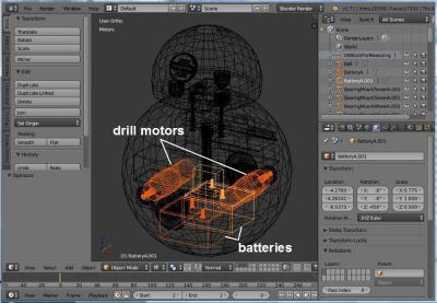
Batteries and motors in Blender
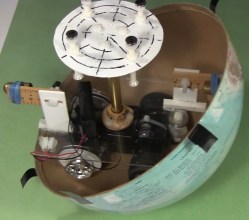
For more powerful motors and more mass I figured I could kill two birds with one stone by going with drill motors and drill batteries in a hamster drive configuration. Using drill parts kept costs down as the batteries and one drill came from yard sales while the other drill was free through freecycle.org. Meanwhile, both are heavy.
To make sure it all fit, I drew up a 3D model in Blender, the free 3D modelling and animation software that I use a lot. In fact, finding out how to make the batteries and motors fit was the first step. They had to be as low as possible. Their large mass low down is what keeps the droid vertical, with the much lighter head at the highest point.
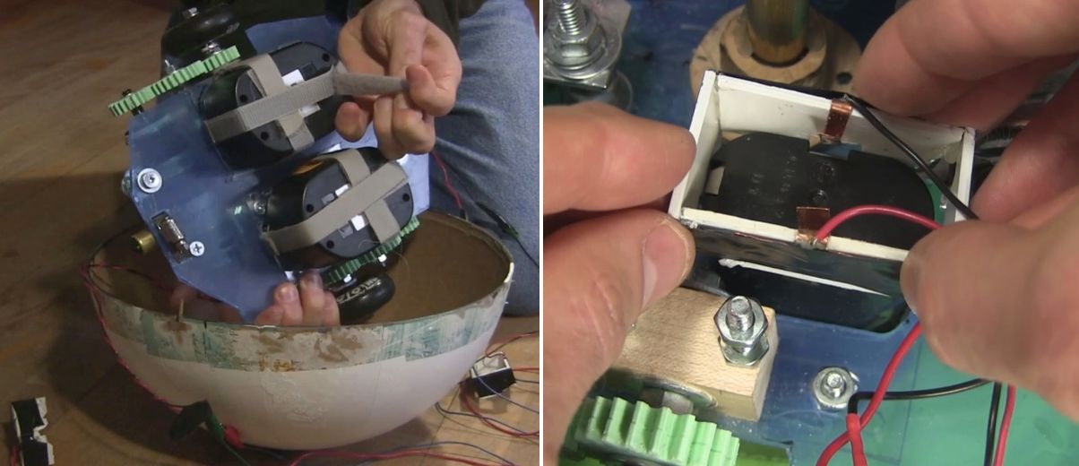
Batteries Velcroed and a connector
The drill batteries had to be easily removable for recharging. To hold them under the drive plate I simply used Velcro. Meanwhile, the drill battery stems went up through a hole in the drive plate. I made a connector to electrically connect to the battery terminals. It is a plastic rectangle with thin copper sheet metal for the contacts. Once the battery was Velcroed in place, this plastic and metal piece was lowered down onto the stem, the copper metal making contact with the battery terminals.
The Electronics
For the brains I used an Arduino UNO. To drive the motors I had all the parts for making two H-bridge driver boards, with the exception of 4 MOSFETs and some fuses. The Arduino does pulse width modulation (PWM) to the driver boards for speed control, as well as playing sounds at certain times when the motors are turned on.
For remote control, I hacked the RC receiver from the toy truck and added an extra set of AA batteries in parallel for more runtime. A problem I ran into right away though, was that the RC receiver put out voltages of both polarities based on which direction the motors should rotate, whereas the Arduino’s pins take only positive voltages. To solve that I came up with a converter board to go between them.
Getting all that to work reliably took a while. Before I added fuses, I burned a few MOSFETs. At one point I’d put an N-type MOSFET where a P-type should have gone and vice versa. That resulting problem alone took a few days of spare time to figure out.
The wheels were old Rollerblade wheels — I keep a small bucket of these in my shop. I decided I wanted the ball to roll at around 1 foot per second and doing the math, that meant the wheels would have to rotate at around 2 rotations per second or 120 RPM. I found a PWM value that would give something close to that and started blowing fuses. I started with 1 amp fuses, then 2, 5, and finally settled on 10 amp fuses.
My final hurdle was that the motors would behave oddly when the motors were told to turn in opposite directions but were fine when they were told to turn in the same direction. This turned out to be a bad assumption on my part about how the RC receiver was wired internally — none of the output wires were common inside. After some changes to the circuit, I now had stable electronics.
I had basically been treating the RC receiver as a black box, but when I asked for help about my converter board here on Hackaday, it was pointed out that the receiver likely contained H bridges. Opening it up, that’s exactly what I found. The converter board works fine for now, but in the near further I’ll use one of the suggestions from that Hackaday post to eliminate the board altogether. I might even try all of the suggestions, just for fun.
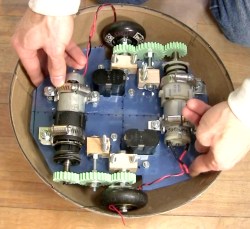
The Drive System
The drive system
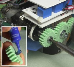
The motors were too long to fit in line between the wheels and so had to be mounted off to the sides. To transfer rotation to the wheels, I drew up some gears in Blender and 3D printed them at our local University of Ottawa Makerspace. In the print settings I used 2 shells and only 50% infill. The gears are held firmly onto the shafts solely using nuts and washers on either side. They’ve held up amazingly well, even with slipping and grinding during development.
For the bearings for the center gears and the wheels I used an old trick of making bearing blocks from hardwood.
Putting Loctite and screwing gear to motor shaft
I wanted to keep as much room as possible on the drive plate available for adding things later and so initially I’d mounted the motors at only three points. But this allowed the motors to move a little causing the gears to slip. To fix that I later added a fourth mounting point and haven’t had any slipping since.
At the end of the shaft for the drill motors is a hole that a screw goes into. That’s part of how the chuck is kept on a drill motor, and that’s how one gear was kept on. However, this screw had a tendency to get loose. Putting a little Loctite on the threads fixed that.
Stability
Rearranging BB-8’s internals
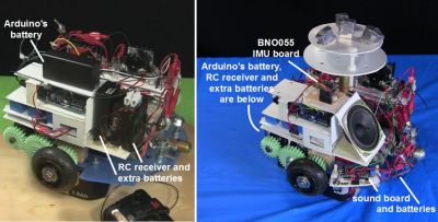
Given that I was trying to fit a lot in a small droid, I had to mount some things higher than I’d have liked to. When the droid stops, mass high up causes the droid to wobble. In the BB-8 droid used for promotional events they’ve gone to a great extent to keep the majority of the mass as low as possible. Originally I had the Arduino batteries and the RC receiver with its extra batteries fairly high up. I later mounted them much lower. When holding the internals in my hands I could tell the difference but it didn’t make a noticeable difference with the wobble.
Instead, for that I added Adafruit’s BNO055 inertial measurement unit (IMU) board. With it I could tell what angle the droid was at when stopping and experimented with PID loops and other algorithms of my own to minimize wobble. That helped.
The Ball
As I said, I used a 12″ cardboard globe. To increase the traction of the wheels inside the globe I sprayed the globe’s interior with an anti-slip spray from a hardware store. This made a huge difference. However, over time the anti-slip coating vanished, and so I’m looking for another, more permanent coating, perhaps urethane or something. If anyone has any suggestions, please let me know in the comments. It also has to stop off-gassing eventually. The anti-slip spray had an odor for a long time.
Sealing globes – cardboard and fiberglass
But the main problem with the cardboard globe was its thinness. With the huge weight of the internals pushing down on it where the wheels are, it warped significantly and required a lot of effort and a copious amount of tape to keep the two hemispheres together. This large amount of tape also made an uneven ridge for the head to slide over, making it get stuck. At that point either the drive system continued to move while the head fell off or the drive system couldn’t move at all.
The solution was to carefully coat a new globe in three layers of fiberglass. I took my time doing this, over a month and a half, applying one piece at a time and then sanding before putting the next piece. The result was a fantastic improvement. It no longer deformed and now it takes a minimal effort to attach the two hemispheres with only eight narrow strips of transparent duct tape.
The Never-ending Saga
My DIY BB-8 in action
My BB-8 is now at the point that I can call it finished. At least it’s finished as far as all the engineering is concerned, and that’s usually where I call it quits.
While the paint job worked out well, up close you can see that the details are painted on. It’d be nice to have at least the lines on the head be actual grooves. Also, these drill motors are brushed motors and I’ve since learned that doing high frequency PWM to brushed motors damages them over time. I’d like to replace them with brushless motors. And as anyone who’s use cordless drills a lot knows, drill batteries don’t last long, and so it’d be great to switch to LiPos.
But for now, the reactions I get from both kids and adults is beyond my wildest expectations. Kids threat it like a friend while adults have petted it and called to it like it was a baby or a dog wagging its tail. I’d call that a success.
I have a good background working with high voltage, which for me means over 10,000 volts, but I have many gaps when it comes to the lower voltage realm in which RC control boards and H-bridges live. When working on my first real robot, a BB-8 droid, I stumbled when designing a board to convert varying polarities from an RC receiver board into positive voltages only for an Arduino.
Today’s question is, how do you convert a negative voltage into a positive one?
In the end I came up with something that works, but I’m sure there’s a more elegant solution, and perhaps an obvious one to those more skilled in this low voltage realm. What follows is my journey to come up with this board. What I have works, but it still nibbles at my brain and I’d love to see the Hackaday community’s skill and experience applied to this simple yet perplexing design challenge.
The Problem
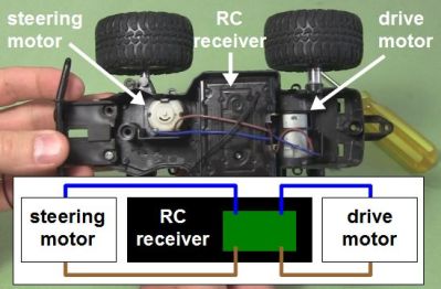
RC toy truck and circuit with no common
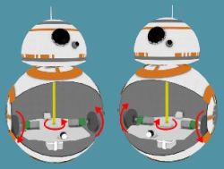
I have an RC receiver that I’ve taken from a toy truck. When it was in the truck, it controlled two DC motors: one for driving backwards and forwards, and the other for steering left and right. That means the motors are told to rotate either clockwise or counterclockwise as needed. To make a DC motor rotate in one direction you connect the two wires one way, and to make it rotate in the other direction you reverse the two wires, or you reverse the polarity. None of the output wires are common inside the RC receiver, something I discovered the hard way as you’ll see below.
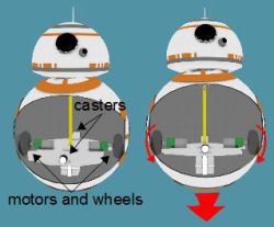
I wasn’t using the RC receiver with the toy truck. I extracted it from the truck and was using it to control my BB-8 droid. My BB-8 droid has two motors configured as what in the BB-8 builders world is called a hamster drive, though is more widely known as a tank drive or differential drive (see the illustrations). Rotate both wheels in the same direction with respect to the droid and the droid moves in that direction. Reverse both wheels and it drives in the opposite direction. Make the wheels rotate in opposite directions and it turns on the spot.
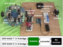
The big picture – RC to drill motors
The motors in my BB-8 are drill motors and are controlled by two H-bridge boards. An Arduino does pulse width modulation to the H-bridge boards for speed control, and controls which direction the motors should turn. Finally, the RC receiver is what tells the Arduino what to do. But a converter board, the subject of this article, is needed between the RC receiver and the Arduino. Note that the Arduino is necessary also for countering when the BB-8 droid wobbles and for synchronizing sounds with the movement, but those aren’t addressed here.
Since there are two motors and two directions for each motor, the RC receiver needs to control four pins on the Arduino to make the two drill motors behave as follows: motor 1/clockwise, motor 1/counterclockwise, motor 2/clockwise, motor 2/counterclockwise. And whatever voltages the receiver puts on those pins has to be relative to the Ardunio’s ground.
And herein lies the problem. The Arduino expects positive voltages with respect to its ground on all those pins. So I needed a way to map the RC receiver’s two sets of motor control wires, which can have either positive or negative voltages across them, to the Arduino pins which only want positive voltages. And remember, none of those RC receiver wires are common inside the receiver.
My Fumbling First Approach
Now, keep in mind, electronics is a general interest of mine and except for what we were taught in high school physics class, I’m self-taught. That means I’ve “read ahead” but much of my knowledge has been determined by what projects I’ve done. So I have gaps in my knowledge. I’d never turned negative voltages into positive before. It sounded simple enough. Searching online didn’t help though. The closest I got was in two old posts in forums where the answers were “It’s easy to do. I can do it with a single resistor.” But there was no further explanation and I didn’t ask my own question anywhere at that point.
Using a transistor
Instead I came up with my own approach with just one set of wires from the RC receiver first. The wires coming from the receiver were blue and brown and could have either polarity depending on which way the receiver is being told to rotate the motor: clockwise or counterclockwise. That meant I needed two diodes to create two possible paths for the different polarities the brown wire could be: positive or negative. I then added a battery for the one path that was negative, to turn it into a positive.
Next, I put a PNP transistor between the positive of the battery and the receiver. With no signal from the RC transmitter, the transistor’s base is negative with respect to the emitter, but not enough to turn the transistor on. That’s because the battery’s negative is connected to the receiver’s blue wire and since there’s no signal from the transmitter, the brown wire is also at the same potential as the blue wire, and with battery negative.
The idea was that when the transmitter sent a signal to make that brown wire negative with respect to the blue wire, it would become even more negative and turn on the PNP transistor. A positive signal would then go from the battery, through the transistor to the Arduino.
The most obvious problem was that the Arduino wanted to see 3 volts to register as a HIGH input, meaning the battery would have to be at least 3 volts and so even with no signal from the transmitter, that would be -3 volts to the transistor, turning it on when it wasn’t supposed to be on.
Using A Relay Instead
Using a relay
And so I immediately thought of using a relay instead. I’d use the current running through the negative path to energize the relay, closing a switch that was completely independent of the RC receiver. The Arduino has a 5V output pin, so I made that switch close a circuit between the 5V pin and the Arduino’s pin 7, giving pin 7 the needed positive voltage.
The 1 in the circle in the schematic shows where I wanted to put a resistor in order to limit the current going through the relay’s coil. However, I tried with resistors all the way down to 4.7 ohms but the coil didn’t have enough current to close the switch. With no resistor, it worked and the current was 70mA. The relay’s coil was rated for 3V/120mA so I left it.
Using a relay did seem very heavy-handed, but it was the only solution I could come up with and I already had the relay in stock.
The next step was to add a second relay, doing the same for the second set of wires coming from the RC receiver for the second motor.
No Common In The Receiver
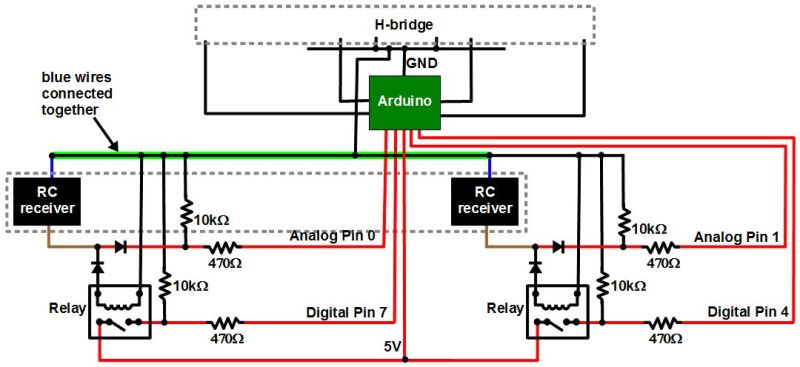
Schematic with common blue RC wires
But the behavior was seemingly sporadic. And keep in mind that there was a whole dual H-bridge circuit that was also connected to the Arduino’s ground. I’d worked with relays a lot before, and the RC receiver came from a commercially made and functional toy so I had no reason to suspect that. On the other hand, I’d made the H-bridge circuit from scratch since I already had most of the parts, and I was new to H-bridges and MOSFETs. So at first I spent a good two weeks of spare time thinking my problem was with the H-bridge and drill motor side. I’m sure we’ve all experienced the same blindness, thinking the most likely culprit is the part you had a hand in.
But at some point I disconnected the H-bridge and tested just the RC receiver circuit, watching the voltages at the Arduino pins while I remotely turned on both “motors” in both directions in all combinations (no motors were connected at the time though). The only odd behavior I saw was when I turned the motors on in opposite directions.
Notice in the schematic that I’d connected together both blue wires coming from the RC receiver. Up to that point I’d been assuming that the blue wires were common inside the receiver and that it was only the brown wires that switched from positive to negative with respect to the blue wires. From the behavior I was seeing it looked like both wires were switching polarity, possibly around some other internal common reference.
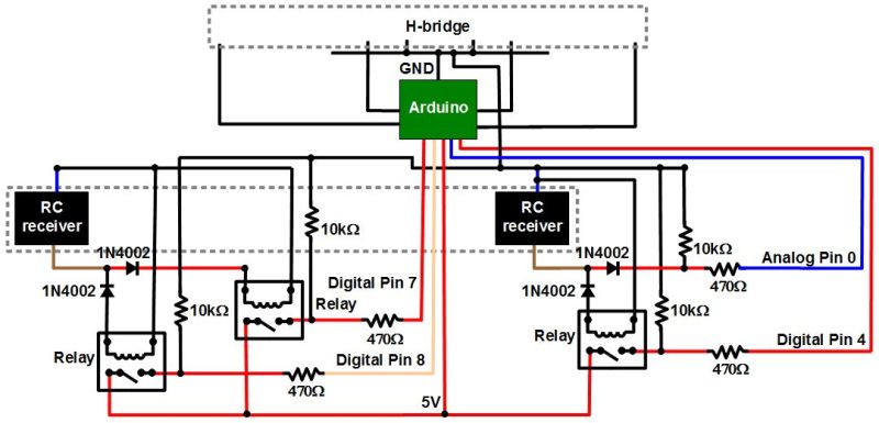
Finished RC-to-Arduino converter schematic
So I added a third relay on one of the positive paths of one of the sets of wires. That meant the corresponding blue wire no longer needed to be grounded, keeping both of the receiver’s blue wires separate. Note that I didn’t bother putting in a fourth relay for the remaining positive path, and it turned out to not be necessary. At that point the circuits worked great and continue to do so.
The Ask
And so I ask, is there a better way to convert the RC receiver output to something the Arduino can use? Relays require power, so it would be nice if there was a solution that didn’t require any extra power. My relay solution seems very early 1900s. Or maybe it’s a good solution after all, but just one of many. Let us know in the comments below.
A vise, a hacksaw and file, some wrenches – the fanciest tools [HomoFaciens] uses while building his DIY hardware store CNC machine (YouTube link) are a drill press and some taps. And the bill of materials for this surprisingly precise build is similarly modest: the X- and Y-axes ride on cheap bearings that roll on steel tube stock and aluminum angles; drives are threaded rods with homemade encoders and powered by small brushed DC gear motors; and the base plate appears to be a scrap of ping-pong table. The whole thing is controlled by an Arduino and four H-bridges.
The first accuracy tests using a ball point pen for tooling are quite impressive. [HomoFaciens] was able to draw concentric circles eyeball-accurate to within a few tenths of a millimeter, and was able to show good repeatability in returning to a point from both directions on both the X- and Y-axis. After the pen tests, he shows off a couple of other hardware store tooling options for the Z-axis – a Proxxon rotary tool with a burr for engraving glass; a soldering iron for cutting styrofoam; and a mini-router that works well enough to cut some acrylic gears.
We’re impressed by this build, which demonstrates that you don’t need a fancy shop to build a CNC machine. If you’re getting the itch to jump into the shallow end of the CNC pool, check out some of the builds we’ve featured before, like this PVC CNC machine, or this $250 build.
I am really new to robotics, and only just recently got my arduino uno. i've played around a bit here and there to learn how to control servo's and such, so i figured it's time for me to build my first robot. but in the design, i've come across a few problems: