Posts with «processing» label

Darkroom Robot Automates Away the Tedium of Film Developing

Anyone who has ever processed real analog film in a darkroom probably remembers two things: the awkward fumbling in absolute darkness while trying to get the film loaded into the developing reel, and the tedium of getting the timing for each solution just right. This automatic film-developing machine can’t help much with the former, but it more than makes up for that by taking care of the latter.

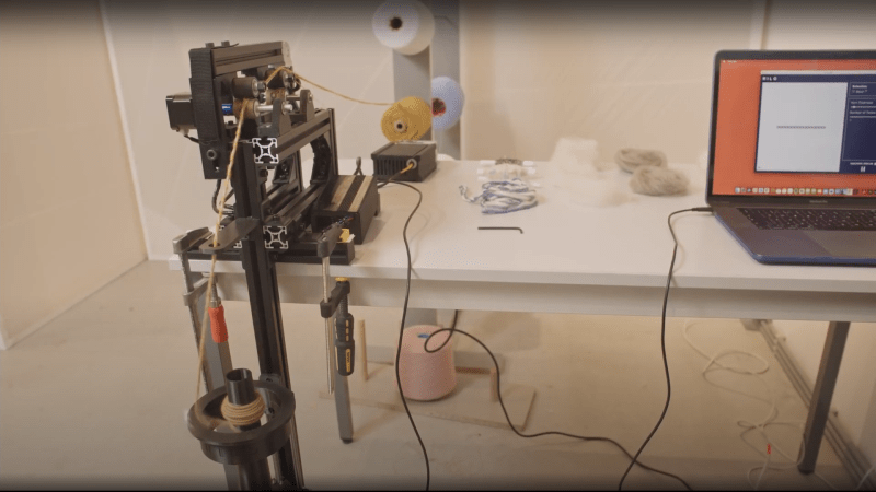
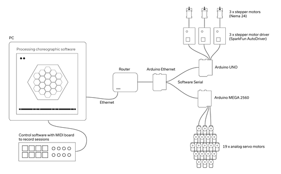
For those who haven’t experienced the pleasures of the darkroom — and we mean that sincerely; watching images appear before your eyes is straight magic — film processing is divided into two phases: developing the exposed film from the camera, and making prints from the film. [kauzerei]’s machine automates development and centers around a modified developing tank and a set of vessels for the various solutions needed for different film processes. Pumps and solenoid valves control the flow of solutions in and out of the developing tank, while a servo mounted on the tank’s cover gently rotates the reel to keep the film exposed to fresh solutions; proper agitation is the secret sauce of film developing.

The developing machine has a lot of other nice features that really should help with getting consistent results. The developing tank sits on a strain gauge, to ensure the proper amount of each solution is added. To avoid splotches that can come from using plain tap water, rinse water is filtered using a household drinking water pitcher. The entire rig can be submerged in a heated water bath for a consistent temperature during processing. And, with four solution reservoirs, the machine is adaptable to multiple processes. [kauzerei] lists black and white and C41 color negative processes, but we’d imagine it would be easy to support a color slide process like E6 too.

This looks like a great build, and while it’s not the first darkroom bot we’ve seen — we even featured one made from Lego Technics once upon a time — this one has us itching to get back into the darkroom again.

An Open Hardware Automatic Spinning Machine

The team at the Berlin-based Studio HILO has been working on ideas and tools around developing a more open approach to small-scale textile production environments. Leveraging open-source platforms and tools, the team has come up with a simple open hardware spinning machine that can be used for interactive yarn production, right on the desktop. The frame is built with 3030 profile aluminium extrusions, with a handful of 3D printed, and a smidge of laser cut parts. Motion is thanks to, you guessed it, NEMA 17 stepper motors and the once ubiquitous Arduino Mega 2560 plus RAMPS 1.4 combination that many people will be very familiar with.

The project really shines on the documentation side of things, with the project GitLab positively dripping with well-organised information. One minor niggle is that you’ll need access to a polyjet or very accurate multi-material 3D printer to run off the drive wheel and the associated trailing wheel. We’re sure there’s a simple enough way to do it without those tools, for those sufficiently motivated.

We liked the use of Arduino for the firmware, keeping things simple, and in the same vein, Processing for the user interface. That makes sending values from the on-screen slider controls over the USB a piece of cake. Processing doesn’t seem to pop up on these pages too often, which is a shame as it’s a great tool to have at one’s disposal. On the subject of the user interface, it looks like for now only basic parameters can be tweaked on the fly, with some more subtle parameters needing fixing at firmware compilation time. With a bit more time, we’re sure the project will flesh out a bit more, and that area will be improved.

Of course, if you only have raw fibers, that are not appropriately aligned, you need a carder, like this one maybe?

Thanks [Daniel] for the tip!

3D Printed SCARA Arm With 3D Printer Components

One of the side effects of the rise of 3D printers has been the increased availability and low cost of 3D printer components, which are use fill for range of applications. [How To Mechatronics] capitalized on this and built a SCARA robot arm using 3D-printed parts and common 3D-printer components.

The basic SCARA mechanism is a two-link arm, similar to a human arm. The end of the second joint can move through the XY-plane by rotating at the base and elbow of the mechanism. [How To Mechatronics] added Z-motion by moving the base of the first arm on four vertical linear rods with a lead screw. A combination of thrust bearings and ball bearings allow for smooth rotation of each of the joints, which are belt-driven with NEMA17 stepper motors. Each joint has a microswitch at a certain position in its rotation to give it a home position. The jaws of the gripper slide on two parallel linear rods, and are actuated with a servo. For controlling the motors, an Arduino Uno and CNC stepper shield was used.

The arm is operated from a computer with a GUI written in Processing, which sends instructions to the Arduino over serial. The GUI allows for both direct forward kinematic control of the joints, and inverse kinematic control,  which will automatically move the gripper to a specified coordinate. The GUI can also save positions, and then string them together to do complete tasks autonomously.

The base joint is a bit wobbly due to the weight of the rest of the arm, but this could be fixed by using a frame to support it at the top as well. We really like the fact that commonly available components were used, and the link in the first paragraph has detailed instructions and source files for building your own. If the remaining backlash can be solved, it could be a decent light duty CNC platform, especially with the small footprint and large travel area. This is very similar to a wooden SCARA robots we’ve seen before, except that one put the Z-axis at the gripper. We’ve also seen a few 3D printers and pen plotters that used this layout.

Arduino Does Multitouch

A lot of consumer gadgets use touch sensors now. It is a cheap and reliable way to replace a variety of knobs and switches on everything from headphones to automobiles. However, creating a custom touch controller for a one-off project can be daunting. A recent ACM paper shows how just about any capacitive sensor can work as a multitouch sensor with nothing more than an Arduino although a PC running processing interprets the data for higher-level functions.

The key is that the Arduino excites the grid using PWM and then examines the signal coming out of the grid. Finger poking changes the response quite a bit and the Arduino can sense it using the analog to digital converters onboard. You can find the actual software kit online. The tutorial document is probably more interesting than the ACM paper if you only want to use the kit.

The optimum drive frequency is 10 MHz. The examples rely on harmonics of a lower frequency PWM signal to get there. The analog conversion, of course, isn’t that fast but since your finger touch rate is relatively slow, they treat the signal as an amplitude-modulated input which is very easy to decode.

The sensors can be conductive ink, thread, or copper strips. There are several example applications, including a 3D printed bunny you can pet, a control panel on a sleeve, and an interactive greeting card.

The sensor forms an image and OpenCV detects the actual touch configuration. It appears you can use the raw data from the Arduino, too, but it might be a little harder.

We imagine aluminum foil would work with this technique. If you get to the point of laying out a PCB, this might come in handy.

Arduino and processing based GUI person counter

In this post, we will make arduino and processing based GUI person counter. For person counter, we are using infrared sensor (IR). It's output is digital and is fed to pin number 7 of arduino.

The connections are as follows:


Arduino Code:

int switchPin=7;
int ledPin=13;

void setup() {
pinMode(switchPin,INPUT);
digitalWrite(switchPin,HIGH);
pinMode(ledPin,OUTPUT);
Serial.begin(9600);
}

void loop() {
  if(digitalRead(switchPin))
    {
    while(digitalRead(switchPin));        
    Serial.print(1,DEC);
    }
  else
    {
    Serial.print(0,DEC);
    }
    delay(100);
} 

Processing Code:

import processing.serial.*;

Serial port;
int val;
int count=0;
PFont f;                           // STEP 1 Declare PFont variable

void setup()  {
    size(400,400);
    noStroke();
    println(Serial.list());  // print list of available serial port 
    port=new Serial(this,Serial.list()[0],9600);        
    f = createFont("Arial",16,true); // STEP 2 Create Font
 }
  
void draw()  {
  if(0<port.available())
  {
    val=port.read();
  } 
    background(204);
    println(val);

  if(val==48)
{     fill(255,0,0);   // red
  rect(50,50,300,300);  // green
}
  else if(val==49)
{     fill(0,255,0);   // green
  rect(50,50,300,300);  // green
  count++;
}

  textFont(f,30);               
  fill(0);                         
  text("Number of Person is: " + count , 30, 30);
//text(count, 100, 100);
delay(100);

 }

/* END OF CODE */

Music Box Plays “Still Alive” Thanks to Automated Hole Puncher

Custom hole punch and feed system

Most projects have one or two significant aspects in which custom work or clever execution is showcased, but this Music Box Hole Punching Machine by [Josh Sheldon] and his roommate [Matt] is a delight on many levels. Not only was custom hardware made to automate punching holes in long spools of paper for feeding through a music box, but a software front end to process MIDI files means that in a way, this project is really a MIDI-to-hand-cranked-music-box converter. What a time to be alive.

The hole punch is an entirely custom-made assembly, and as [Josh] observes, making a reliable hole punch turns out to be extremely challenging. Plenty of trial and error was involved, and the project’s documentation as well as an overview video go into plenty of detail. Don’t miss the music box version of “Still Alive”, either. Both are embedded below.

As [Josh] mentioned on his project page, he was inspired by a tutorial video showing how to punch music by hand. It led to this tool to take a MIDI file and cut the music paper out on a laser cutter, whereas [Josh] and [Matt] were inspired to automate the entire process in their own way.

For those of you who don’t think science should stop there, why not automate the creation of the music itself with the output of this Bach-emulating Recurring Neural Network?

Thanks to [Tim Trzepacz] for giving us a heads up on this delightful project!


Filed under: musical hacks

Particle Flow makes granules tumble in interesting patterns

This Arduino-based project creates interesting tumbling patterns using a system that tilts a plane in a controlled manner while deforming its surface.

NEOANALOG, a “studio for hybrid things and spaces,” was commissioned to build the Particle Flow installation, which explores how granules tumble under the control of gravity. This mechanism takes the form of a large hexagon held in three corners by linkages pushed up and down by NEMA 24 stepper motors. As these rods are lifted, the granules inside the “arena” are steered over to the opposite side producing a zen-like experience.

Inside the main hexagon are 19 smaller hexagons, each controlled by servos to lift an individual section of the rolling surface up and down. Control of the entire system is accomplished via a PC running Processing, which sends commands via Ethernet to an Arduino Mega and the steppers to an Arduino Uno with three motor drivers. 

A moving slanted plane and a grid of motorized stamps control the elements to form infinite variations of behaviors and patterns. The result is a zen-like experience that is both: fascinating and contemplative. Software controlled motion follows a complex choreography and enables precise steering of physical particles in a variety of ways: from subtle to obvious, from slow to high paced, from random-like to symmetric.

Intrigued? Be sure to check out Creative Applications Network’s write-up on this piece as well as NEOANALOG’s page for more details.

DIY Vacuum Chamber Proves Thermodynamics Professor Isn’t Making It All Up

[Mr_GreenCoat] is studying engineering. His thermodynamics teacher agreed with the stance that engineering is best learned through experimentation, and tasked [Mr_GreenCoat]’s group with the construction of a vacuum chamber to prove that the boiling point of a liquid goes down with the pressure it is exposed to.

His group used black PVC pipe to construct their chamber. They used an air compressor to generate the vacuum. The lid is a sheet of lexan with a silicone disk. We’ve covered these sorts of designs before. Since a vacuum chamber is at max going to suffer 14.9 ish psi distributed load on the outside there’s no real worry of their design going too horribly wrong.

The interesting part of the build is the hardware and software built to boil the water and log the temperatures and pressures. Science isn’t done until something is written down after all. They have a power resistor and a temperature probe inside of the chamber. The temperature over time is logged using an Arduino and a bit of processing code.

In the end their experiment matched what they had been learning in class. The current laws of thermodynamics are still in effect — all is right in the universe — and these poor students can probably save some money and get along with an old edition of the textbook. Video after the break.


Filed under: Arduino Hacks, tool hacks

Cartesio – low cost cartesian plotter robot

Primary image

What does it do?

Plotter robot arm

Recently the famous site evilmadscientist introduced the new art robot called Axidraw.I saw the robot in action and it is very similar to the robot I built in the 2015, called Cartesio, a 3d printed cartesian robot.

Cost to build

$60, 00

Embedded video

Finished project

Complete

Number

Time to build

Type

URL to more information

Weight

read more

How to turn data into cocktails!

Data Cocktail is a device which translates in a tasty way the Twitter activity and running on Arduino Due and Arduino Pro Mini. When you want a cocktail, the machine will look for the five latest messages around the world quoting one of the available ingredients. These messages define the drink composition and Data Cocktail not only provides a unique kind of drink, but it also prints the cocktail’s recipe along with the corresponding tweets.
Once the cocktail mix is done, Data Cocktail thanks the tweeters who have helped at making the recipe, without knowing it. Check the video below to see how it works:

Data Cocktail was created in a workshop held at Stereolux in Nantes by a theme composed by Bertille Masse, Manon Le Moal-Joubel, Sébastien Maury, Clément Gault & Thibaut Métivier.

They made it using Processing and Arduino:

A first application, developed in Processing, pilots the device. The requests are performed using the Twitter4J library, then the application processes the data and controls the device, i.e. the robot, the solenoid valves and the light. The robot itself is based on a modified Zumo frame, an Arduino Pro, a Motor Shield and a Bluetooth module. The solenoid valves and the LEDs are controlled by an Arduino Due connected via USB. The impression is realized by Automator.

To prepare a cocktail, the machine can take up to a minute and may provide up to 6 different ingredients!