Posts with «tips and tricks» label

Assembling the Pro Mini OLED clock shield kit

Customers complained about the lack of documentation on the Pro Mini OLED clock kit.

I listened and I agree. Even though the silkscreen should provide the necessary directions for soldering the parts on the shield itself, adding the Pro Mini board and the OLED display are still ambiguous, especially because there are multiple options.

Here is a quick, but hopefully adequate, step-by-step guide on one way to assemble this clock kit.

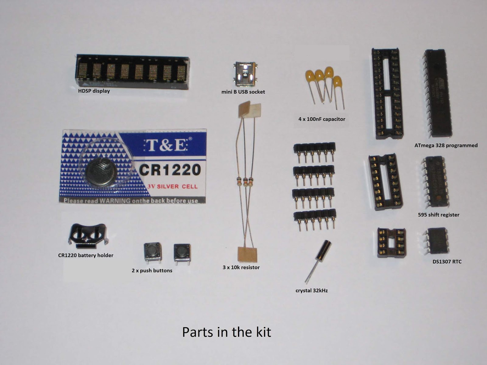
1. Make sure you source the correct Pro Mini board, that looks similar to the one in the photos below. It features an ATmega328 clocked at 16MHz.


Note that SCL and SDA (A5, A4 respectively) are broken out. Also, the FTDI connects directly to the side of the Pro Mini board.


2. Program the board itself with the OLED Clock sketch. In Tools/Board, select "Arduino Duemilanove w/ ATmega328". Upload using the FTDI adapter. This step is important because you want to make sure your Pro Mini works before you mount/solder it.

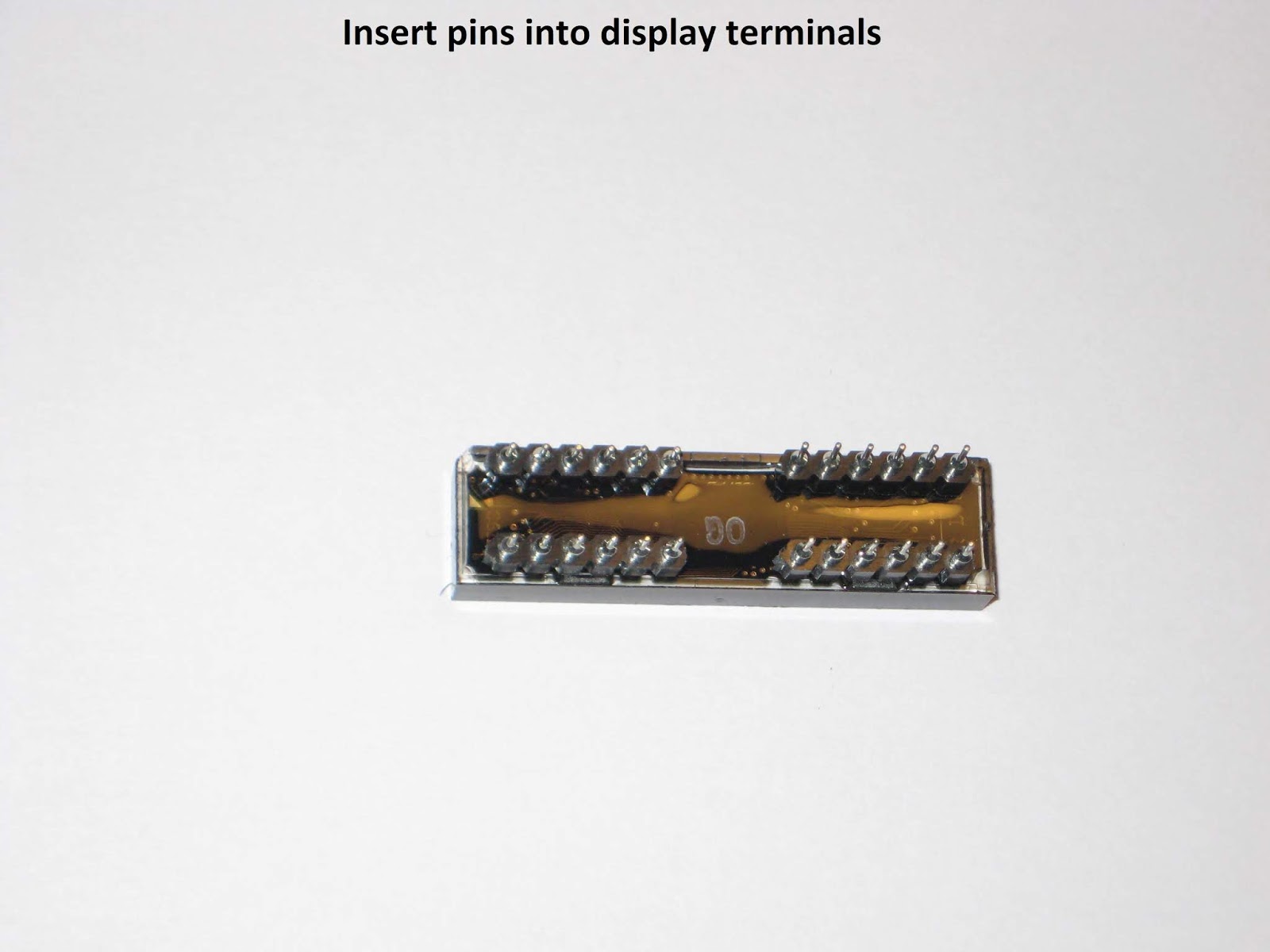
3. Make sure you source the correct I2C 128x64 OLED display, like the one shown below.


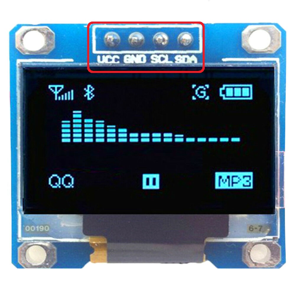
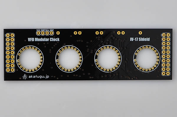
The pins at the top must be in the order (left to right) VCC-GND-SCL-SDA or VCC-GND-SDA-SCL.

In case your display has a different arrangement of the pins, e.g. GND-VCC-SCL-SDA, you will need to swap the leftmost two pins, by rewiring the traces (cut, then reconnect) on the shield's PCB (not on the display, which remains untouched), as explained in Step 6.

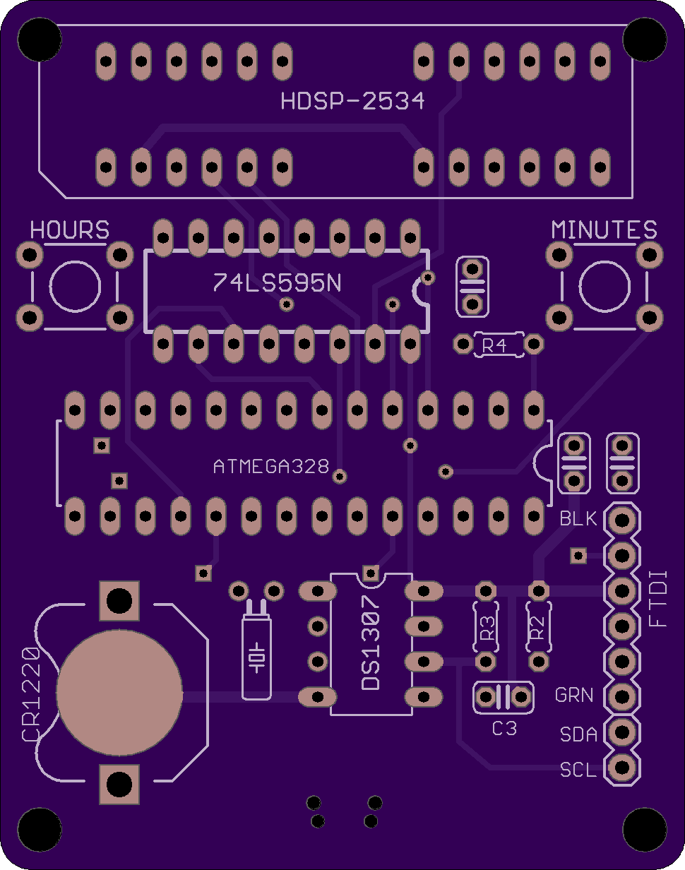
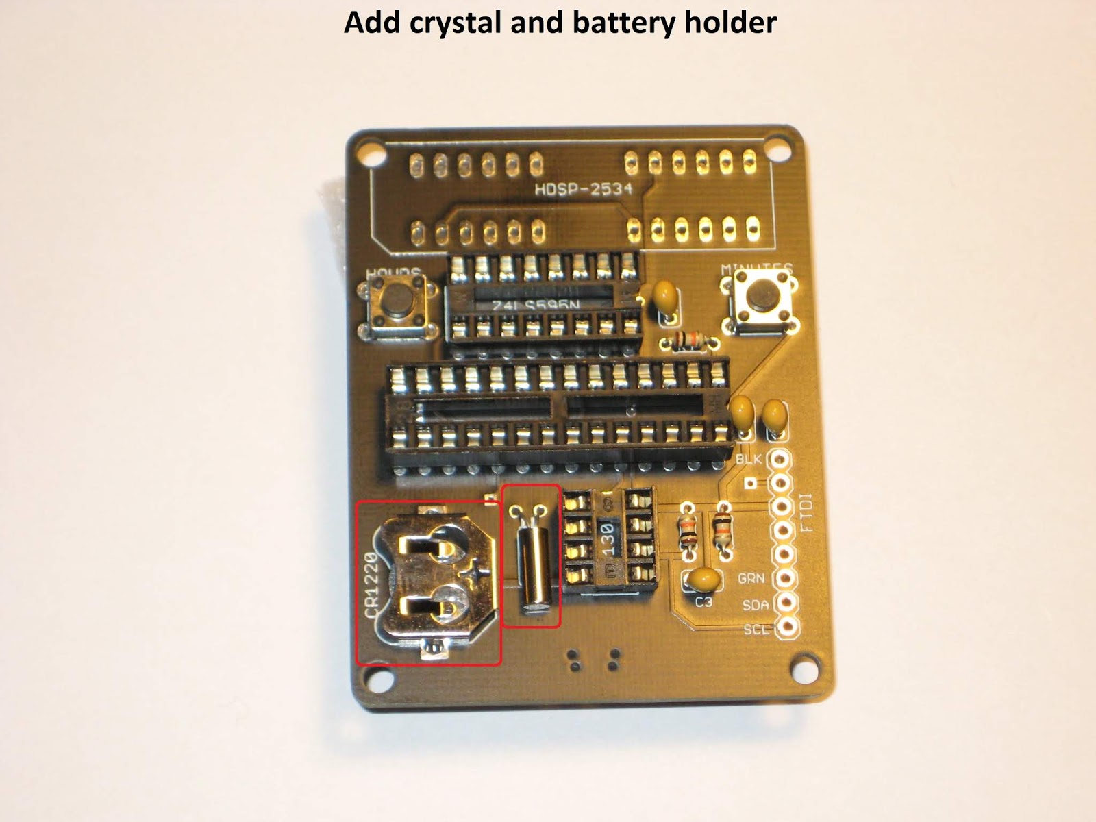
4. Solder the DS1307, paying attention to the correct orientation (notch up), then the 2 resistors and the crystal.

5. Solder the 2 jumper bridges according to the OLED display you are going to use.


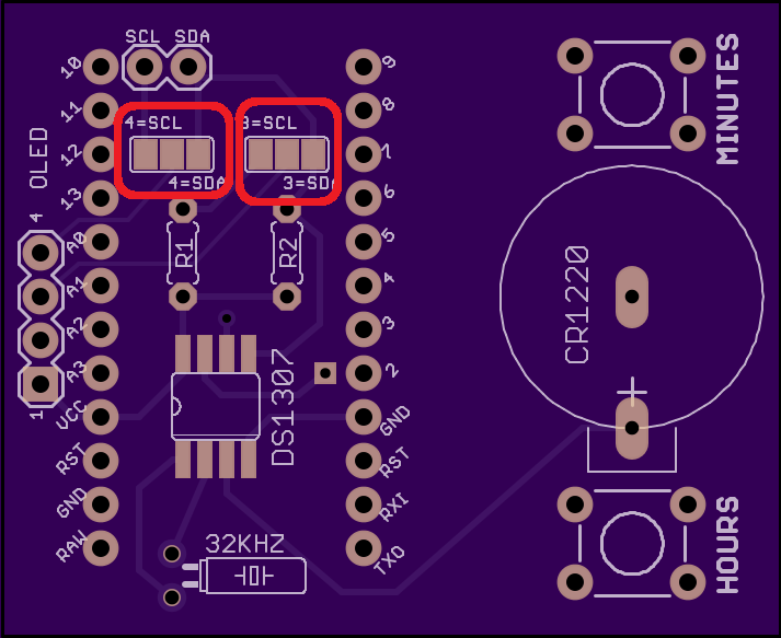
If your OLED has pin 3 and 4 configured as SCL and SDA respectively, then solder the right bridge of the left jumper and the left bridge of the right jumper (see the photo below).


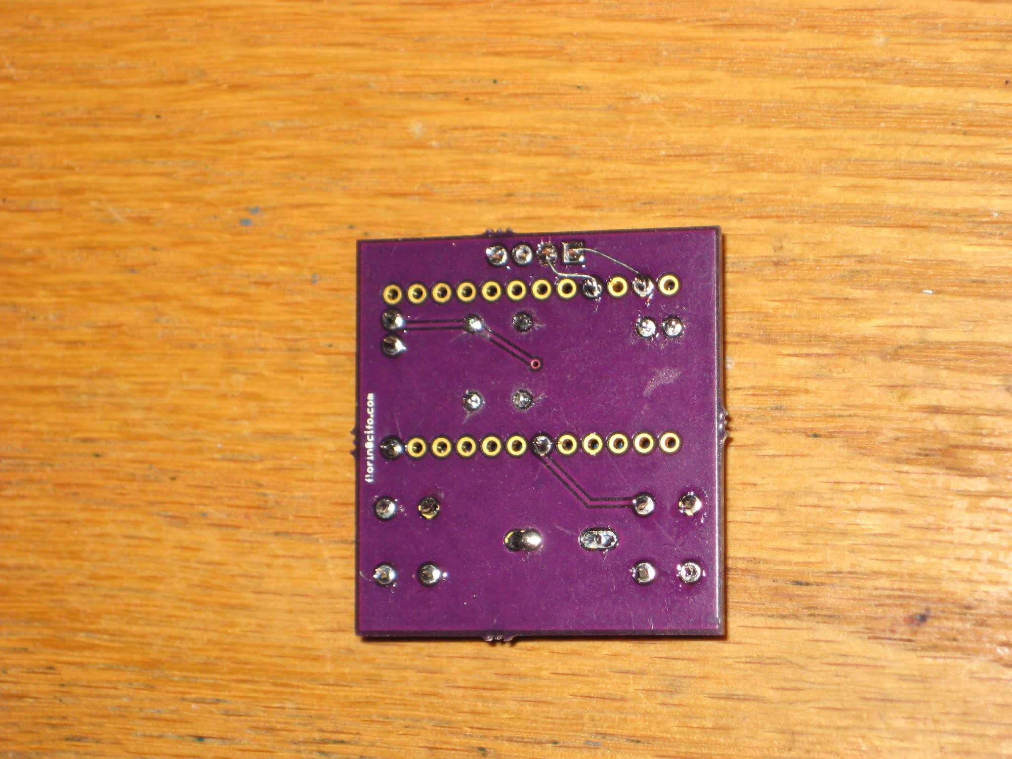
6. Only if necessary
Remember, the Pro Mini OLED shield was designed for I2C OLED displays that have pin 1 as VCC and pin 2 as GND. If that is not the case (as in the photo below),

those first 2 pins must be rewired, as shown (after the traces had been cut and pins isolated).


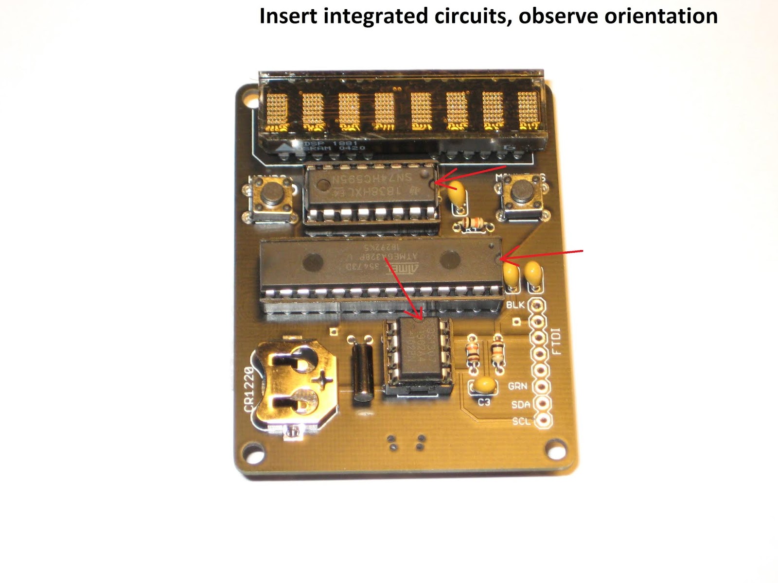
7. Solder the Pro Mini board on top and close to the OLED shield, using machined male pins (included in the kit). Only the relevant pins, highlighted in the photo below, need to be soldered.


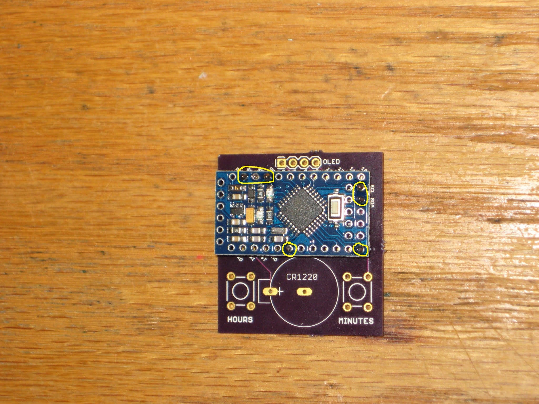
Pay attention, since this is a hard-to-reverse move. Fixing a mistake here involves de-soldering. Also, the parts underneath cannot be (easily) accessed anymore.

8. Solder the 4-pin female header, the 2 buttons and the battery holder, then insert the CR1225 battery, with the correct polarity (+ on top).


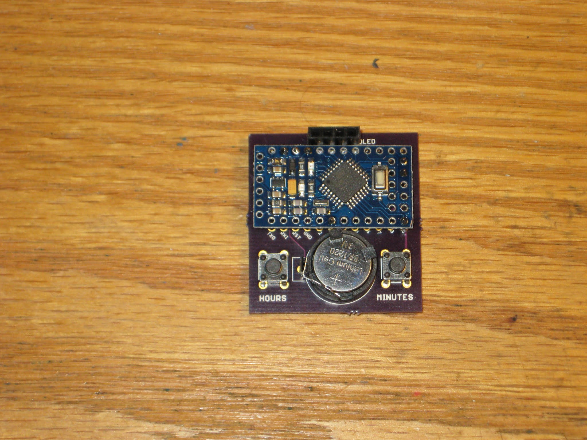
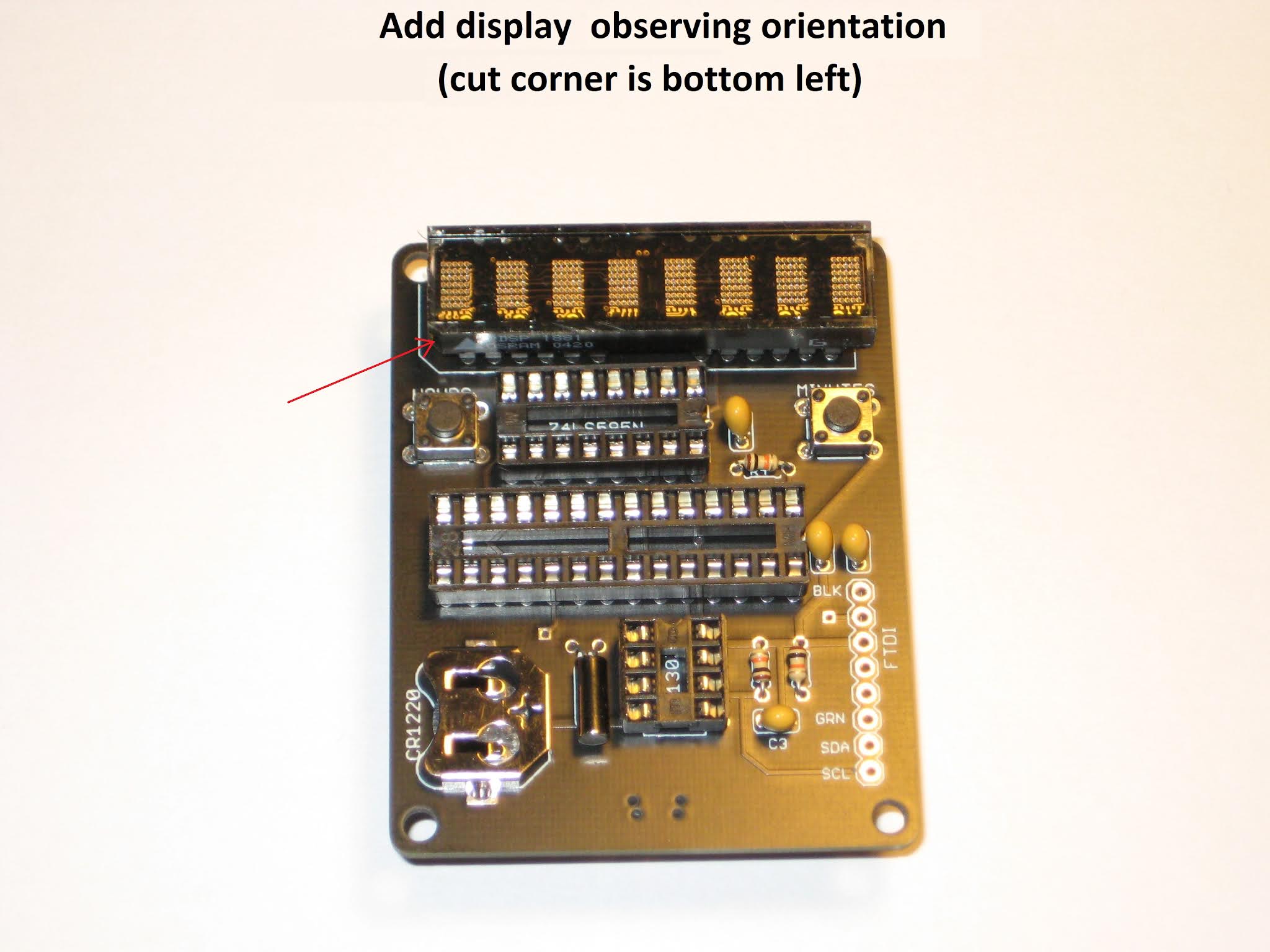
9. Insert the OLED display.

10. Power the clock through the FTDI breakout (observe the correct orientation) or by directly wiring VCC and GND to a 5V or battery source.
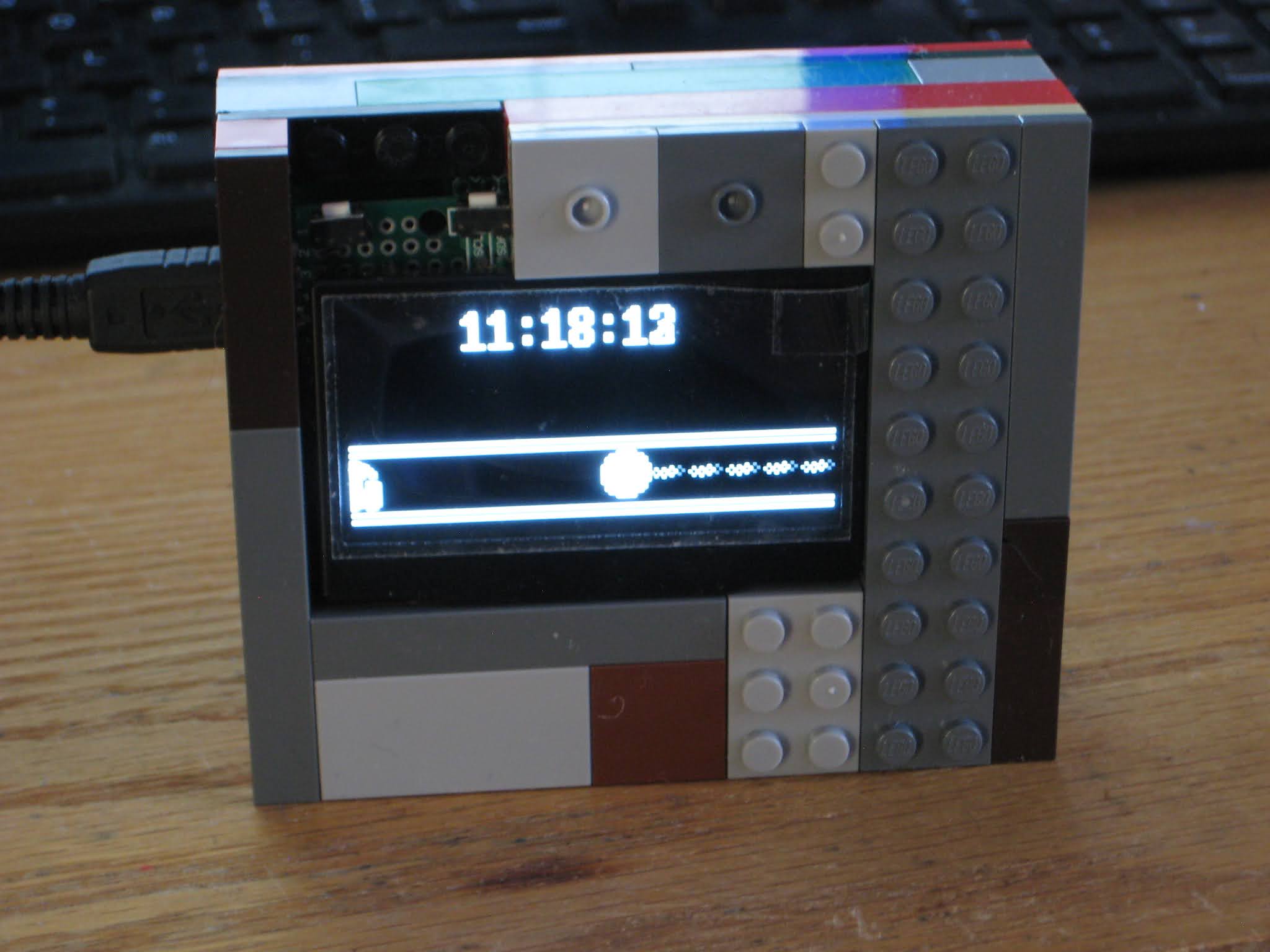
Any of the 5 clock faces can be selected by pushing simultaneously the 2 buttons.
Pressing each button individually will increment either the hours or the minutes.


Enclosure ideas for WiFiChron and other clocks

It turns out that most electronics, even prototypes, can be easily enclosed with Lego. And that means no screws, no glue, no fasteners, zero tools, just the bricks and some imagination.

This is the HDSP clock variant with 1" displays driven by HT16K33 (introduced here). The board was cut and filed (0.5mm on each side) to fit snug between the walls (see this).


Next is a HDSP clock variant with two Adafruit Quad Alphanumeric displays.


Similarly, the PCB was cut and filed a bit. The assembly fits solidly between the bricks (no movement when shaken). As in the previous build, the exposed PCB is kind-of-required to allow access to the two buttons (set hours, set minutes).

Both of the above can be mounted on a Lego wall (as found in schools) or they can desk-stand on their own.

Here is an example of a Lego-encapsulated WifiChron.


The PCB was also filed about 0.5mm on each side to fit between the lateral brick walls. It did not have to be fastened in any other way. The ESP8266 module fits inside nicely. The 3 buttons and the USB mini B connector are all easily accessible from the back.

Below is the Lego version of the Axiris clock.


Since it does not have any buttons, the time is set through Bluetooth (command "SET TIME=hh:mm", sent from Terminal app while BT paired).

And finally, a couple of OLED clocks, both running the same software on similar hardware: pro-mini + OLED shield and wsduino + 2.42" OLED shield, respectively.


Note that this is the prototype version, using a LiPo battery with charger (similar to the one shown here).


Again, all the above enclosures feel solid: nothing moves or rattles when upside down or even shaken. I did not try dropping them though :)

And lastly, the WiFiChron with Adafruit quad 0.56" displays from the previous post, sandwiched between scrap plexiglass plates:


HDSP clock revision 2

The latest revision of the HDSP clock uses the same schematic, but offers an improved PCB layout, with:
  • 4 holes in the corners, for encasing;
  • addition of I2C signals to the FTDI connector, for expansion;
  • the regular push buttons can be replaced with 2-pin right angle buttons;

This revision was successfully used as the assembly kit in the "Introduction to Practical Electronics" course for Grade 6 students.

This would also be a good place for step-by-step assembly instructions, for those who require directions.


melt a bit of solder on the battery pad, to raise it (not pictured)


slide in the CR1220 battery, flat side (+ pole) up (not pictured)


Use a mini B USB cable to power the clock. It should work right away, since the processor is already programmed with the clock software. Use the "Hours" (left) and "Minutes" (right) buttons to set up the time.
Also, insert the CR1220 battery into the holder. It powers the DS1307 RTC (real time clock) when the clock board is disconnected from USB. Note that the small coin battery ONLY powers the RTC integrated circuit, and not the whole clock. The display is lit only when connected to the USB power.

Troubleshooting
  • check for missing soldering joints; you may have forgotten to solder some terminals;
  • check for solder bridges; solder blobs may accidentally connect adjacent holes/terminals that should not be connected;
  • make sure the orientation of the integrated circuits and the display matches the silkscreen, by checking the notches/indentations;
  • ensure that the ICs are fully and completely pushed in the socket, until their bottoms touch the socket's plastic;

What's next

1. Catch up on the theory:
  • recognize components symbols in schematics;
  • recap units of measure for some of the components (ohms for resistors, farads for capacitors); read their intended values (3 digits, color code), measure their real values using a multimeter;
  • understand electrical concepts: voltage, current, resistance (and their dependency), frequency; recap their units of measure;
2. Design and make an enclosure (hint: the easiest is to sandwich the board between plates of transparent acrylic, with standoffs in the 4 corners).

3. Look for a new kit to assemble.

Introduction to practical electronics for children

I designed this 7-hour (one hour/day) course for 6 graders, as part of their STEM curriculum.
The goal is to introduce the children to practical electronics and teach them about:

1. electronic parts/components: how to identify/recognize them, how to measure (using a multi-meter), what they are used for (role in an electronic circuit):
  • resistors (current reduction), variable resistor/potentiometer, trimmer
  • capacitors (energy accumulator), variable capacitor
  • transistors (amplification)
  • coils (inductors)
  • diodes, LEDs
  • speakers. microphones
  • buttons, switches
  • integrated circuits, processors
  • displays
  • sensors (light, magnetic, proximity/infrared/ultrasound)
  • servo motors
  • relays
2. how to solder (using a soldering station), how to place and position parts on a board, how to check connection, how to follow steps of an instruction manual;

3. electricity and electronics concept:
  • voltage, current, resistance;
  • AC vs DC
  • digital vs analog
  • oscillation
  • rectification
  • amplification
  • series, parallel
  • voltage transformation (AC)
  • voltage regulation (AC, DC)
4. basic understanding/reading of schematics (wiring, electrical connections).


Required materials

Course schedule

Day 1
theory: introduction to components; presentation and identification (1/2 hour)
practice: beginning soldering (1/2 hour) LED + resistor, using flux, soldering wire, wick, on prototype PCBs;

Day 2
theory: introduction of a simple clock kit or another, more familiar to me, simple HDSP clock kit; assembly analysis, component placement and positioning;
practice: solder passive components on PCB; assemble the HDSP clock;

Day 3
theory: more on components; introduction to schematics;
practice: solder the active components of the clock kit;

Day 4
theory: electricity concepts (digital vs analog);
practice: finishing up the kit assembly; power, test, use;

Day 5
theory: electricity concepts (voltage, current, resistance); example of other kits;
practice: learn to use an ohm/volt/meter;

Day 6
theory: electronics concepts (oscillation, rectification, amplification, sound generation etc.);
practice: bring an electronic toy, working or not; disassembly, analysis, repair (if needed);

Day 7
practice: continuation from Day 6; identification of components used in the toy; understanding of how it works; modding/expanding functionality/adding LEDs, speaker, buttons etc.;


We are already on "Day 3", but behind schedule. Soldering is harder for the kids than I originally thought. One thing that I overlooked was that each student needs individual attention/supervision on the practical side (soldering, component placement etc.). Half hour per day of hands-on practice is definitely too short at this level. The schedule may be a little aggressive for the average Grade 6, probably better suited for older and more disciplined students. In any case, I am working on adjusting the content of the course and the feedback I receive is amazing. Kids really enjoy the fact that it is practical and some of them are amazed when they see the LEDs they soldered actually lighting up.


M4 receiver backpack for reliable wireless remote control

My investigation into the failure of the M4 receiver remote controlling my Wise Clock 4 concluded with the need to add a step-up converter. The Sure 1632 display makes the input voltage drop sometimes below the absolute minimum of 4.5V required for the M4 module to work properly. It's not the noise (spikes) in the 5V power, nor the interference on 315MHz.

I designed a simple "M4 receiver backpack" that uses a DC-DC step-up converter to ensure a 5V power for the M4 receiver module. The board supports 2 different kinds of converters, one from ebay (red in the photo below), the other from tindie (made by BBtech, black in the photo).


The backpack can be used, by default, without the step-up converter if the voltage is steady at around 5V. (A trace-jumper must be cut when a converter is added.)

The wireless remote pair of 4-key fob transmitter and receiver module is sold by Adafruit or vendors on ebay.

The assembled board wired to Wise Clock 4 is shown in the photos below. Note that only 3 out of 4 buttons on the remote have a function on the clock. Each button press could light up a (optional) LED on the receiver board for visual confirmation.


A new design of the Wise Clock 4 board should probably feature a header for plugging in the receiver module, otherwise the back of the board will show a bunch of ugly wires.


This M4 receiver backpack could be used for adding remote control to other devices with buttons, especially when these buttons are hard to access (due to enclosure design constraints), or hidden (for aesthetic purpose). One example that comes to mind is an oscilloscope clock fully enclosed in transparent acrylic; drilling holes for the buttons would require some design stretches.

The M4 receiver backpack would be also suitable for hacking an old alarm clock. Please let me know if anyone is interested :)

My first impression on Cogwheel Nixie clock

Many months ago I bought, attracted by the clearance price, the PCB for the "Nixie Driver Board Rev A" from "Cogwheel circuit works" store. I was hoping that, with all documentation in place, I would be able to build it on my own, considering it's controlled by an ATmega328 and the software was available, though not the source code.

First thing to note is that the board uses mostly SMDs. If anything went wrong (and there was a high chance, since the PCB was already described as a "mistake the board house made"), the board would become a coaster.

The schematic includes some exotic components, like the HV513 Nixie driver, not offered by digikey. Others are the DS1302 RTC and the optional DS32KHZ oscillator for RTC, which I heard of for the first time. But thanks to the detailed BOM, gathering the components was relatively (some of them are already discontinued, for example) easy.

High voltage for the Nixie tubes is generated by a hardware PWM under software control. So, like the Ice Tube Clock, in order to measure the high voltage and make sure the HV circuitry works, some software must be uploaded onto the processor. I expected the released software to do that. Unfortunately, the highest voltage I saw was under 9V.


After some digging (and learning in the process), I ended up with this simple sketch, adapted from Satashnik Nixie clock, which generates a stable 190V. I know, I was surprised too :)

#include "Arduino.h"

#define DDRHVPUMP  DDRB
#define BV2(a,b) (_BV(a)|_BV(b))
#define BV6(a,b,c,d,e,f) (_BV(a)|_BV(b)|_BV(c)|_BV(d)|_BV(e)|_BV(f))
#define VOLTAGE_WASTE   370                     //!< ~180V
#define VOLTAGE_SAVE    355                     //!< ~170V

volatile uint16_t voltage; 
static volatile uint16_t voltage_setpoint = VOLTAGE_WASTE;
static const uint16_t ocr1a_reload = 60;

void pump_init()
{
    // set fast pwm mode
    // COM1A1:0 = 10, clear oc1a on compare match, set at top
    // COM1B1:0 = 00, normal port operation
    // no FOC
    // WGM11:10 (WGM = Fast PWM, TOP=ICR1: 1110) = 11
    TCCR1A = BV2(COM1A1, WGM11);
    TCCR1B = BV2(WGM13,  WGM12);
    OCR1A = ocr1a_reload; 
    ICR1 = 170;
    TCCR1B |= _BV(CS10); // clk/1 (16MHz)
    DDRHVPUMP |= BV2(1,2);
}

void adc_init()
{
    voltage = 0;
    // PORTA.6 is the feedback input, AREF = AREF pin
    ADMUX = 6;  
    // ADC enable, autotrigger, interrupt enable, prescaler = 111 (divide by 32)
    ADCSRA = BV6(ADEN, ADATE, ADIE, ADPS2, ADPS1, ADPS0); 
    ADCSRA |= _BV(ADSC); 
}

/// Start voltage booster
void voltage_start()
{
    adc_init();
    pump_init();
}

ISR(ADC_vect)
{
    voltage = (voltage + ADC) / 2;
    if (voltage < voltage_setpoint) {
        OCR1A = ocr1a_reload;
    } else {
        OCR1A = 0;
    }
}

void setup()
{
    sei();
    voltage_start();        // start HV generation    
}

void loop()
{
  // clock functionality in here;
}

The next big step is to write the software to drive the tubes and actually show the time, which is essentially re-writing the Cogwheel Nixie clock code (or at least the basic functionality) from scratch. Then open source it. Any help would be appreciated :)

The ugliest project I've built so far

Based on this photo from BroHogan's gallery of Geiger counters, it was supposed to be a simple encasing using Adafruit's Arduino enclosure. Everything looked neat and clean inside, even with room to spare.
I wanted to use LiPo instead of AAA batteries, to avoid opening and closing the device every so often. This required the use of a LiPo charger, for which I picked the one I already had, the seeedstudio's LiPo Rider.

I spent countless hours trying to put this puzzle together:
  • only 4 places for screws;
  • small(ish) charger board must to be solidly anchored to the case (since an USB cable will be plugged in frequently), yet it does not have any hole for screws;
  • 6 wires (battery, V out, switch) must be soldered to the charger SMD board;
  • 12 wires need to connect the Geiger board to the LCD, on the other half of the case;
  • trim pot suspended somewhere (since there is no room for it on the PCB);
  • power switch to fit in the rectangular opening of the bottom ;

When I thought I figured it out, the two halves of the case wouldn't close because things inside were too tall/thick. Back to the "drawing board". Took out the ATmega328 from the Geiger board (it was touching the LCD connectors, which were already minimized for space), and replaced it with a cheap ($4) "Arduino Nano" (or is it "Mini") from ebay. This also helped immensely with the wiring: instead of connecting 12 wires between the case halves (Atmega328 to LCD), I had to solder only 3 (Vcc, Gnd, Int).


After a few more kludges (e.g. re-positioned the inductor on its side, removed the (over)power(ing) LED on Arduino Nano), I ended up with something , as the saying goes, "only a mother can love".

The lesson I learned from this experience is that, if one wants a seamless, solid, beautiful, project, one needs to either design the board for an enclosure, or the enclosure for a board. Trying to mix and match the board with the enclosure leads, at best, to something ugly.


Did I mention that I worked on it on and off for about 3 months?
The red light in the bottom left corner is the "charging" LED. (And then there is the somehow annoying LCD's backlight, visible through the translucent enclosure.)


The power switch is advertised as being the smallest rocker power switch out there. I only had to file off about 1mm on the upper side of the original rectangular opening to make it fit.

Another lesson I learned: use a transparent enclosure only when the inside looks perfect and you want to show it, and by "perfect" I mean even no visible wires.

Stay tuned for the next version of this Geiger device. (You did not think I would stop here, did you ? :)

More open source VFD clocks

I just finished assembling the latest version of akafugu VFD clock, the "MK2". Per, from akafugu, generously sent me the board for testing/review. It comes will all SMD components pre-soldered, and the processor pre-programmed. The rest of the components, all through-hole, I sourced on my own.
Here is a photo of the kit as I put it together (I forgot to include the through-hole resistors though).


Assembling was straightforward thanks to the combination of good board design and easy-to-follow instructions. The result is shown in the photo below.


MK2 has some improvements over version 1:
- newer processor (Atmega32U4, as the one used in Leonardo);
- 5V power source (vs 9V previously);
- direct sketch upload from Arduino IDE (no hacking required);
- integrated support (on-board 24LC256 eeprom) for four-letter-word feature;
- all SMD parts (quite a few actually) come pre-soldered;
- directly compatible with the existing (version 1) VFD display shields;
- better clearance with the VFD display shield (because parts are shorter in height).

In conclusion, MK2 is another winner for akafugu.


I also recently assembled the Ice Tube clock from adafruit. I bought the PCB(s) a while ago (when they were still available for sale on adafruit site) and I sourced the parts on my own. I followed the legendary assembly instructions, but things did not go without a glitch for me. Here is what I learned in the process:
  • The Ice Tube clock is not Arduino-compatible as I initially thought (see here). It cannot be programmed from the Arduino IDE and it does not have an FTDI interface/connector. The processor (I used Atmega328, but ATmega168 should work with the base software too) uses the internal 8MHz oscillator and an external 32kHz crystal. This crystal, in conjunction with TIMER2 (see file iv.c), is the heart of the clock "mechanism". (More details on the design can be found here.)
  • The high voltage for the tube is produced with impulses generated from an output pin of the processor (instead of using an external chip, like may other designs). Therefore, high voltage is not there until the chip is correctly programmed.
  • Programming the chip was a bit of a challenge; I used the makefile to build the hex file from the source, but programmed the chip with avrdude directly, as shown in this screenshot (click for bigger picture).

  • IV-18 tubes bought on ebay, even when they are new (with the wire terminals intact) can be defective. Out of the 5 tubes I got, 4 had a blackened spot on the back and one had a white spot, as shown in the photo below. Guess which one did not work.

  • Inserting all 24 wire terminals of the IV-18 tube in their holes is a challenge. I would much rather prefer the solution adopted by akafugu in their VFD clock, with half terminal holes, opening in a big empty circle (as shown below, photo from akafugu).

  • IC sockets, particularly PLCC28, although bought from digikey, can be "defective". Unlike the DIP IC sockets which press each IC pin on two sides, the PLCC28 sockets actually press against the IC pins on one (external) side only. It took me many minutes to figure out that the tube was not lighting up because one socket pin was loose and did not make contact with the IC's pin.
  • MAX6921 VFD driver used in the Ice Tube clock is more than twice as expensive as HV5812 VFD driver used in MK2. Yet, adafruit's Ice Tube Clock is still the cheapest complete (including enclosure) VFD clock kit out there.

Overall, building the Ice Tube clock was a pleasant and rewarding experience, which I recommend to kit-builders at any level. This clock looks compact, sleek, stylish, and stands out in my clock collection.

Wise Clock 4 with Bluetooth

Another thing that was supposed to be easy, but it wasn't: Arduino communicating with Windows XP through Bluetooth.

Like everybody else, I purchased the cheap and ubiquitous Bluetooth module from dealextreme.
I soldered it myself on the XBee-footprinted PCB (bare BTBee from IteadStudio), for a total price of about $8 (compare that to at least $15 as these Bluetooth XBees go for).

Without knowing much about Bluetooth, I plugged this new "BTBee" module in Wise Clock 4 expecting it to be "discovered" by XP (which has an USB Bluetooth dongle). Discovered it was: the name "linvor" appeared in the list of BT devices, with two serial ports attached to it.

Communication between XP and BT module is performed through the serial ports, I figured. Tried CoolTermWin, HyperTerminal, Putty, on both ports, nothing seemed to work. Time to read the documentation (which always reminds me of that joke). I learned that others had similar problems, and some have solved them by installing new BT drivers. The best advice came from this post. Putty did not work for me, so I stuck with what I had, namely HyperTerminal.

So here is my own step-by-step tutorial on how to make an Arduino communicate with Windows XP via a Bluetooth module.
Note: From the Bluetooth perspective, Wise Clock 4 I used for my testing is similar to Arduino.

1. Upload this simple sketch that "echos" what it reads from Bluetooth and also broadcasts a message periodically. The communication between Arduino and the BT module is serial, with a baud rate of 9600, according to the documentation.

#if ARDUINO < 100
  #include
#else
  #include
#endif


void setup()
{
  Serial.begin(9600);
}


void loop()
{
  while (Serial.available())
  {
    // get char from bluetooth;
    char inChar = (char) Serial.read();
    // output it back, between brackets;
    Serial.print('[');
    Serial.print(inChar);
    Serial.print(']');
  }
  // broadcast message;
  Serial.print("millis() from Arduino: ");
  Serial.println(millis());
  delay(2000);
}

2. Power Arduino, with the BT module connected, and let it run the sketch.

3. Make the BT module (on the Arduino) visible to XP, by adding it to the list of Bluetooth devices. For this, click on the "Bluetooth Devices" icon in the tray (bottom right corner of the XP's desktop). You will see this box.


Next, you will see the BT device added to the list, under the name "linvor".


Then select the last option, "Don't use a passkey". Although it makes little sense at this point (since you know that the passkey is 1234, according to the documentation), it is very important to not use a passkey here.


The last step of the wizard shows the two ports that have been added. Write down the "Outgoing COM port", since this is the one we will be using for communication (step 4).


4. Open HyperTerminal to establish the 2-way communication between XP and Arduino, via Bluetooth.
Select, from the list, the COM port specified as "outgoing" for the BT device.


Next, you will be shown this pop-up.


After you click on it, you are prompted to enter the passkey, the one you (reluctantly) skipped in the process of setting up the BT device. Type "1234", as specified in the BT module documentation.


After hitting "Next", you are shown this last confirmation box.


In the same time, the HyperTerminal starts displaying the message coming from Arduino.


Note that, when the COM port was opened in Auto mode, no parameters (bad rate etc) being specified.
Interestingly, after the communication is established, the baud rate is reported as 2400 (for some unexplained reason).
You can also type characters in the HyperTerminal and they will be echoed back (between brackets) by Arduino.

Optionally, if you want to see what you typed (before the echoing from Arduino takes place), you can enable local echo, by selecting "Properties", then "ASCII Setup".


Once the communication between XP (HyperTerminal) and Arduino is established via Bluetooth, the "Status" LED (if you have it soldered) is on continuously. When the BT module is not communicating, the "Status" LED is blinking at a frequency of about 2Hz.

The next time a HyperTerminal session is opened, XP remembers the BT device and the communication params (ports, passkey) and does not ask to set it up again. (I guess that's why it is called "pairing", although this word does not appear anywhere in the process.)


Time to write some serious applications using Bluetooth:)

Wise Clock 4 with Bluetooth

Another thing that was supposed to be easy, but it wasn't: Arduino communicating with Windows XP through Bluetooth.

Like everybody, I purchased the cheap and ubiquitous Bluetooth module from dealextreme.
I soldered it myself on the XBee-footprinted PCB (bare BTBee from IteadStudio), for a total price of about $8 (compare that to at least $15 as these Bluetooth XBees go for).

Without knowing much about Bluetooth, I plugged this new "BTBee" module in Wise Clock 4 expecting it to be "discovered" by XP (which has an USB Bluetooth dongle). Discovered it was: the name "linvor" appeared in the list of BT devices, with two serial ports attached to it.

Communication between XP and BT module is performed through the serial ports, I figured. Tried CoolTermWin, HyperTerminal, Putty, on both ports, nothing seemed to work. Time to read the documentation (which always reminds me of that joke). I learned that others had similar problems, and some have solved them by installing new BT drivers. The best advice came from this post. Putty did not work for me, so I stuck with what I had, namely HyperTerminal.

So here is my own step-by-step tutorial on how to make an Arduino communicate with Windows XP via a Bluetooth module.
Note: From the Bluetooth perspective, Wise Clock 4 I used for my testing is similar to Arduino.

1. Upload this simple sketch that "echos" what it reads from Bluetooth and also broadcasts a message periodically. The communication between Arduino and the BT module is serial, with a baud rate of 9600, according to the documentation.

#if ARDUINO < 100
  #include
#else
  #include
#endif


void setup()
{
  Serial.begin(9600);
}


void loop()
{
  while (Serial.available())
  {
    // get char from bluetooth;
    char inChar = (char) Serial.read();
    // output it back, between brackets;
    Serial.print('[');
    Serial.print(inChar);
    Serial.print(']');
  }
  // broadcast message;
  Serial.print("millis() from Arduino: ");
  Serial.println(millis());
  delay(2000);
}

2. Power Arduino, with the BT module connected, and let it run the sketch.

3. Make the BT module (on the Arduino) visible to XP, by adding it to the list of Bluetooth devices. For this, click on the "Bluetooth Devices" icon in the tray (bottom right corner of the XP's desktop). You will see this box.


Next, you will see the BT device added to the list, under the name "linvor".


Then select the last option, "Don't use a passkey". Although it makes little sense at this point (since you know that the passkey is 1234, according to the documentation), it is very important to not use a passkey here.


The last step of the wizard shows the two ports that have been added. Write down the "Outgoing COM port", since this is the one we will be using for communication (step 4).


4. Open HyperTerminal to establish the 2-way communication between XP and Arduino, via Bluetooth.
Select, from the list, the COM port specified as "outgoing" for the BT device.


Next, you will be shown this pop-up.


After you click on it, you are prompted to enter the passkey, the one you (reluctantly) skipped in the process of setting up the BT device. Type "1234", as specified in the BT module documentation.


After hitting "Next", you are shown this last confirmation box.


In the same time, the HyperTerminal starts displaying the message coming from Arduino.


Note that, when the COM port was opened in Auto mode, no parameters (baud rate etc) being specified.
Interestingly, after the communication is established, the baud rate is reported as 2400 for some unexplained reason.
You can also type characters in HyperTerminal and they will be echoed back, between brackets, by Arduino.

Optionally, if you want to see what you typed (before the echoing from Arduino takes place), you can enable local echo, by selecting "Properties", then "ASCII Setup".


Once the communication between XP (HyperTerminal) and Arduino is established via Bluetooth, the "Status" LED (if you have it soldered) is on continuously. When the BT module is not communicating, the "Status" LED is blinking at a frequency of about 2Hz.

The next time a HyperTerminal session is opened, XP remembers the BT device and the communication params (ports, passkey) and does not ask to set it up again. (I guess that's why it is called "pairing", although this word does not appear anywhere in the process.)


Time to write some serious applications using Bluetooth:)