Single digit clock - method and apparatus
I recently found, at the bottom of a drawer, my forgotten numitron single-tube clock. It has a LiPo battery which still lights up the filaments, but no RTC to actually show time. It has a single button, which activates the display (numitron tube) when pressed. Indeed, some digits flash on, but inconsistently. And, as a clock, one would want to be able to also set the time, which is definitely not possible in this current version.
The required revision consists in:
- adding RTC
- adding a second button
- updating the software (by adding the ability to set the time through buttons)
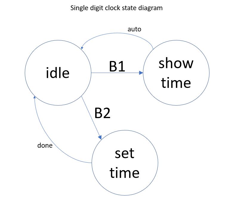
The method I devised for setting up the time follows this state-machine diagram,
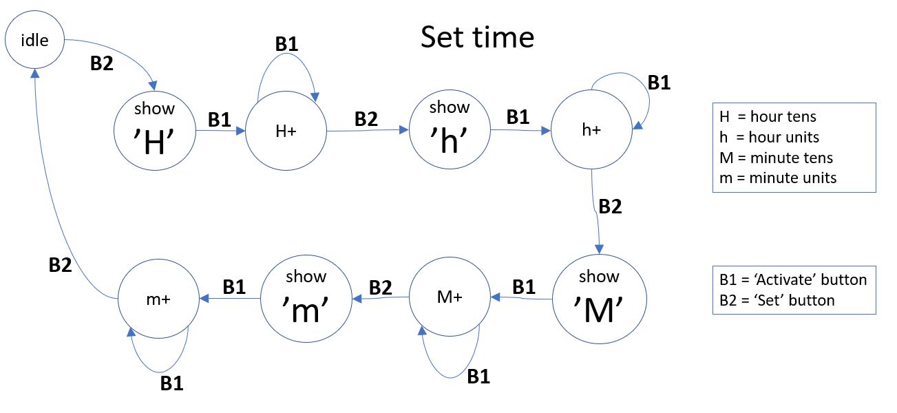
where "Set time" state is part of this bigger picture:
The whole source code file is proudly presented below (as answer to the lots of questions in the above mentioned old post).
/*************************************************************************
* Sketch for direct driving 7-segment numitron IV-9
*
* Segments are defined as follows:
*
*      A
*     ---
*  B |   | C
*     ---  D
*  E |   | F
*     ---
*      G
*
* Decimal point/comma is segment H.
* Common pin is wired to Vcc (would be nice to wire it to D11/MOSI
*      instead, which is also PWM (for brightness)).
* To light up a segment, just connect it to GND.
*
* To display a digit, ground these Arduino pins:
*   0: 6, 7, 8, 10, 11, 13
*   1: 7, 8
*   2: 6, 8, 10, 11, 12
*   3: 6, 7, 8, 11, 12
*   4: 7, 8, 12, 13
*   5: 6, 7, 11, 12, 13
*   6: 6, 7, 10, 11, 12, 13
*   7: 6, 7, 8
*   8: 6, 7, 8, 10, 11, 12, 13
*   9: 6, 7, 8, 11, 12, 13
*
*************************************************************************/

#include <Arduino.h>
#include <Wire.h>
#include "DS1307.h"

#define _DEBUG_

// arduino pins connected to tube terminals;
// chosen based on the natural positioning of the Numitron tube on Pro Mini board;
#define segA  6  	// tube pin 5
#define segB  13	// tube pin 6
#define segC  8  	// tube pin 3
#define segD  12	// tube pin 7
#define segE  10	// tube pin 9
#define segF  7         // tube pin 4
#define segG  11	// tube pin 8
#define segH  9  	// tube pin 2

// button to initiate the setting up of the time;
#define PIN_BUTTON_SET_TIME  4   // D4

// button to activate the display or to increment the time digit;
#define PIN_BUTTON_ACTIVATE  17  // A3


byte segmentPin[8] = {segA, segB, segC, segD, segE, segF, segG};


byte digits[10][7] =
{
// A  B  C  D  E  F  G
  {0, 0, 0, 1, 0, 0, 0}, 	// 0
  {1, 1, 0, 1, 1, 0, 1}, 	// 1
  {0, 1, 0, 0, 0, 1, 0}, 	// 2
  {0, 1, 0, 0, 1, 0, 0},  	// 3
  {1, 0, 0, 0, 1, 0, 1},  	// 4
  {0, 0, 1, 0, 1, 0, 0},   	// 5
  {0, 0, 1, 0, 0, 0, 0},   	// 6
  {0, 1, 0, 1, 1, 0, 1},   	// 7
  {0, 0, 0, 0, 0, 0, 0},   	// 8
  {0, 0, 0, 0, 1, 0, 0}  	// 9
};


byte state[4][7] =
{
// A  B  C  D  E  F  G
  {1, 0, 0, 0, 0, 0, 1}, 	// H
  {1, 0, 1, 0, 0, 0, 1}, 	// h
  {0, 0, 0, 1, 0, 0, 1}, 	// M
  {1, 1, 1, 0, 0, 0, 1},  	// m
};


volatile boolean wasTimeEverSet = false;
volatile boolean showingTime    = false;
volatile boolean settingTime    = false;

byte crtIndex = 0;  // 0..3, index in array timeDigits;
byte timeDigits[4] = {0, 1, 2, 3};
int hour   = 0;
int minute = 0;
int second = 0;
byte  crtValue =  0;  // used when setting the time, one digit at a time (for HHMM);
short crtState = -1;  // used when setting the time;
boolean newState = false;


void setup()
{
#ifdef _DEBUG_
  Serial.begin(9600);
  Serial.println("in setup");
#endif

  // each of display's 7 segment is connected to an output;
  for (byte i=0; i<7; i++)
  {
    pinMode(segmentPin[i], OUTPUT);
  }

  // buttons to activate tube and for setting up the time;
  pinMode(PIN_BUTTON_ACTIVATE, INPUT_PULLUP);
  pinMode(PIN_BUTTON_SET_TIME, INPUT_PULLUP);

  blankDisplay();
}


void loop()
{
  if (digitalRead(PIN_BUTTON_ACTIVATE) == LOW)
  {
#ifdef _DEBUG_
    Serial.print("settingTime=");
    Serial.println(settingTime);
#endif
    delay(200);	// debouncing;

    if (settingTime)
    {
      newState = false;

      crtValue++;
      if (crtValue > 9)
          crtValue = 0;
      displayValue(crtValue);

#ifdef _DEBUG_
      Serial.print ("crtValue=");
      Serial.println(crtValue);
#endif
    }
    else
    {
      getTimeFromRTC();
      splitTime();

      // show time as (h)h-mm;
      showingTime = true;
    }
  }

  if (digitalRead(PIN_BUTTON_SET_TIME) == LOW)
  {
    delay(200);	// debouncing;

#ifdef _DEBUG_
    Serial.print("crtState=");
    Serial.println(crtState);
#endif

    if (crtState == -1)
    {
      // user is initiating setting up the time;
      settingTime = true;
    }

    if (settingTime)
    {
      newState = true;
      crtState++;
    }

#ifdef _DEBUG_
    Serial.print("settingTime=");
    Serial.println(settingTime);
#endif
  }

  if (showingTime)
  {
#ifdef _DEBUG_
    Serial.print  ("show time, digit ");
    Serial.println(crtIndex);
#endif
    if (crtIndex == 0 && timeDigits[0] == 0)
    {
      // do not show the leading 0;
    }
    else
    {
      if (crtIndex == 2)
      {
        // show the dash between hours and minutes;
        displayDash();
        // hold it for a second;
        delay(1000);
      }

      // make the digit flash (otherwise, if 2 consecutive digits are the same, you won't see a difference);
      displayDigit(crtIndex);
      // hold the digit for a second;
      delay(1000);
    }

    crtIndex++;
    if (crtIndex > 3)
    {
      showingTime = false;  // time will show again when button is pressed;
      crtIndex = 0;
      blankDisplay();
    }
  }

  if (settingTime)
  {
    if (newState)
    {
      newState = false;

      // need to save the crtValue;
      if (crtState > 0)
      {
#ifdef _DEBUG_
        Serial.print("set value ");
        Serial.print(crtValue);
        Serial.print(" at index ");
        Serial.println(crtState-1);
#endif
        timeDigits[crtState-1] = crtValue;
      }

      if (crtState > 3)
      {
        settingTime = false;
        crtState = -1;
        blankDisplay();

#ifdef _DEBUG_
        Serial.print("saving time: ");
        Serial.print(10 * timeDigits[0] + timeDigits[1]);
        Serial.print(":");
        Serial.println(10 * timeDigits[2] + timeDigits[3]);
        Serial.print("settingTime=");
        Serial.println(settingTime);
#endif
        // time is set only after all 4 digits (HhMm) were input, that is, after state "m" is left;
        setTime(10 * timeDigits[0] + timeDigits[1], 10 * timeDigits[2] + timeDigits[3], 0);
      }
      else
      {
        displayCrtState();  // one of the 4: H, h, M, m
        // hold it for a bit;
        delay(100);

        // start setting the value from 0;
        crtValue = 0;
      }
    }
  }
}


void displayDigit(byte index)
{
  blankDisplay();
  delay(100);

  byte digit = timeDigits[index];

  // turn on the necessary segments of the digit;
  for (byte i=0; i<7; i++)
  {
    digitalWrite(segmentPin[i], digits[digit][i]);
  }
}


void displayValue(byte crtValue)
{
  blankDisplay();
  delay(100);

  // turn on the necessary segments;
  for (byte i=0; i<7; i++)
  {
    digitalWrite(segmentPin[i], digits[crtValue][i]);
  }
}


void blankDisplay()
{
  // turn off all 7 segments;
  for (byte i=0; i<7; i++)
  {
    digitalWrite(segmentPin[i], 1);
  }
}


void displayDash()
{
  blankDisplay();
  delay(100);
  digitalWrite(segD, 0);
}


void displayCrtState()
{
#ifdef _DEBUG_
    Serial.print  ("crt state is ");
    Serial.println(crtState);
#endif

  blankDisplay();
  delay(100);

  // turn on the necessary segments of the state/letter;
  for (byte i=0; i<7; i++)
  {
    digitalWrite(segmentPin[i], state[crtState][i]);
  }
}


//**********************************************************************************
// Read the entire RTC buffer
//
void getTimeFromRTC()
{
  int rtc[7];
  RTC_DS1307.get(rtc, true);

  // check to avoid glitches;
  if (rtc[DS1307_MIN] < 60 && rtc[DS1307_HR] < 24 && rtc[DS1307_SEC] < 60)
  {
    second = rtc[DS1307_SEC];
    minute = rtc[DS1307_MIN];
    hour   = rtc[DS1307_HR];
  }
/*
  // check to avoid glitches;
  if (rtc[DS1307_YR] <= 2050 && rtc[DS1307_MTH] <= 12  && rtc[DS1307_DATE] <= 31)
  {
    day    = rtc[DS1307_DATE];
    month  = rtc[DS1307_MTH];
    year   = rtc[DS1307_YR];
  }
*/
  // The RTC may have a dead battery or may have never been initialized
  // If so, the RTC doesn't run until it is set.
  // Here we check once to see if it is running and start it if not.
  if (!wasTimeEverSet) {
    wasTimeEverSet = true;
    if (hour == 0 && minute == 0 && second == 0)
    {
      // set an arbitrary time to get the RTC going;
      setTime(10,23,45);
    }
  }

#ifdef _DEBUG_
    Serial.print("Time is ");
    Serial.print(rtc[DS1307_HR]);
    Serial.print(":");
    Serial.print(rtc[DS1307_MIN]);
    Serial.print(":");
    Serial.println(rtc[DS1307_SEC]);
#endif

}


//**********************************************************************************
//
void setTime(int hh, int mm, int ss)
{
  RTC_DS1307.stop();
  RTC_DS1307.set(DS1307_SEC,  ss);
  RTC_DS1307.set(DS1307_MIN,  mm);
  RTC_DS1307.set(DS1307_HR,   hh);
  RTC_DS1307.start();
}


void splitTime()
{
  timeDigits[0] = hour / 10;
  timeDigits[1] = hour % 10;
  timeDigits[2] = minute/10;
  timeDigits[3] = minute%10;
}
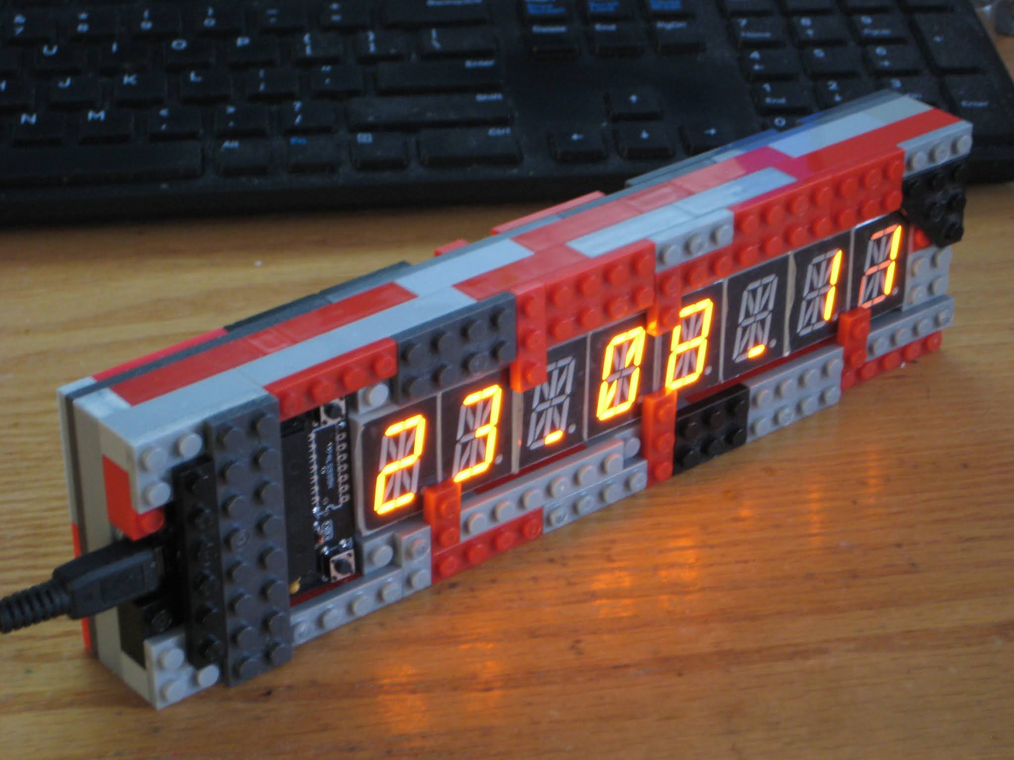
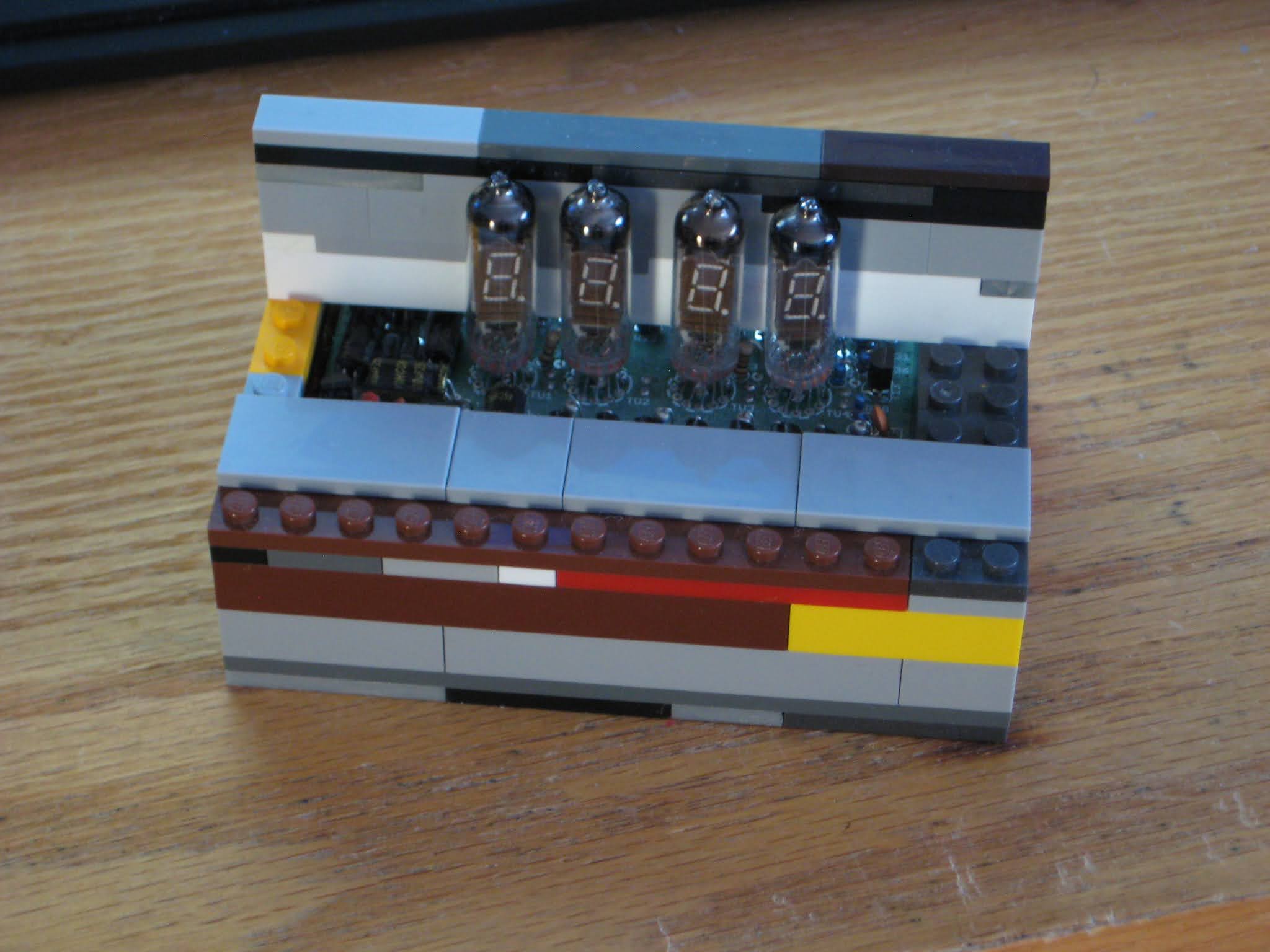
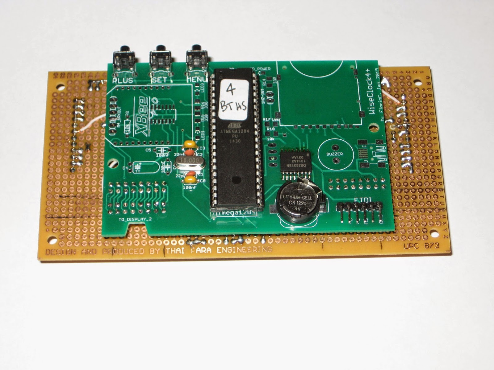
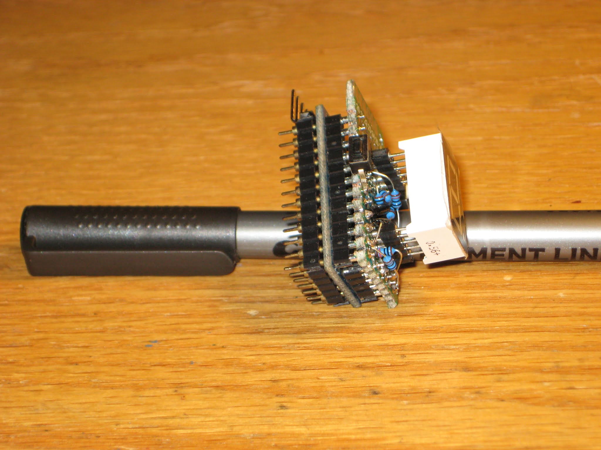
The single digit numitron clock is the simplest possible clock, in terms of the number of components included. The numitron tube is connected directly to the processor's outputs, the common electrode being wired to Vcc. I noticed that the 3.7V LiPo battery is not reliably capable to light up the filaments. USB's 5V gives the tube a stable functionality.
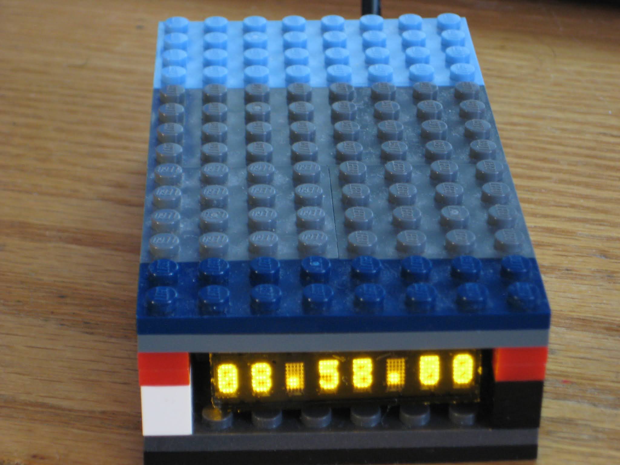
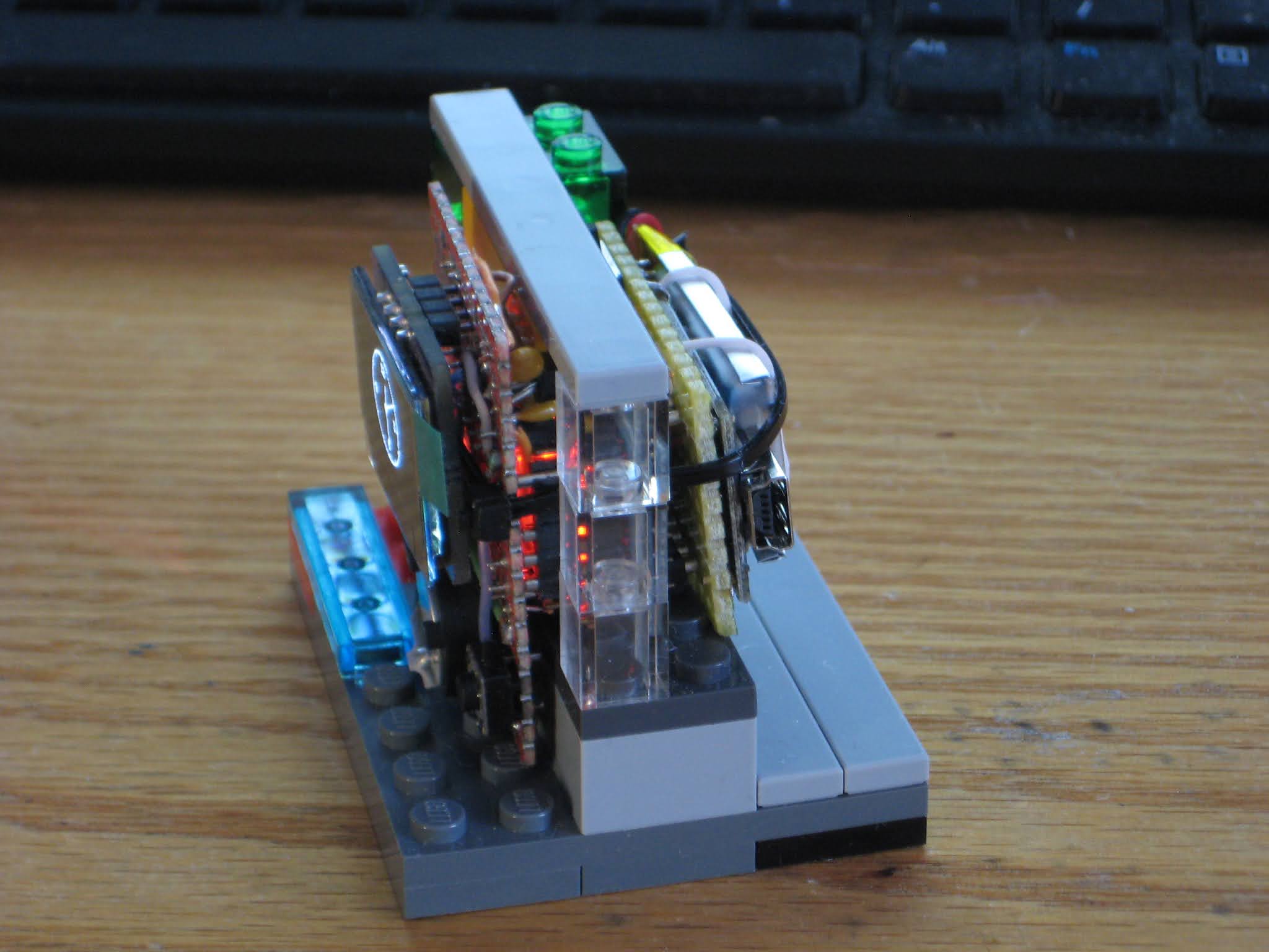
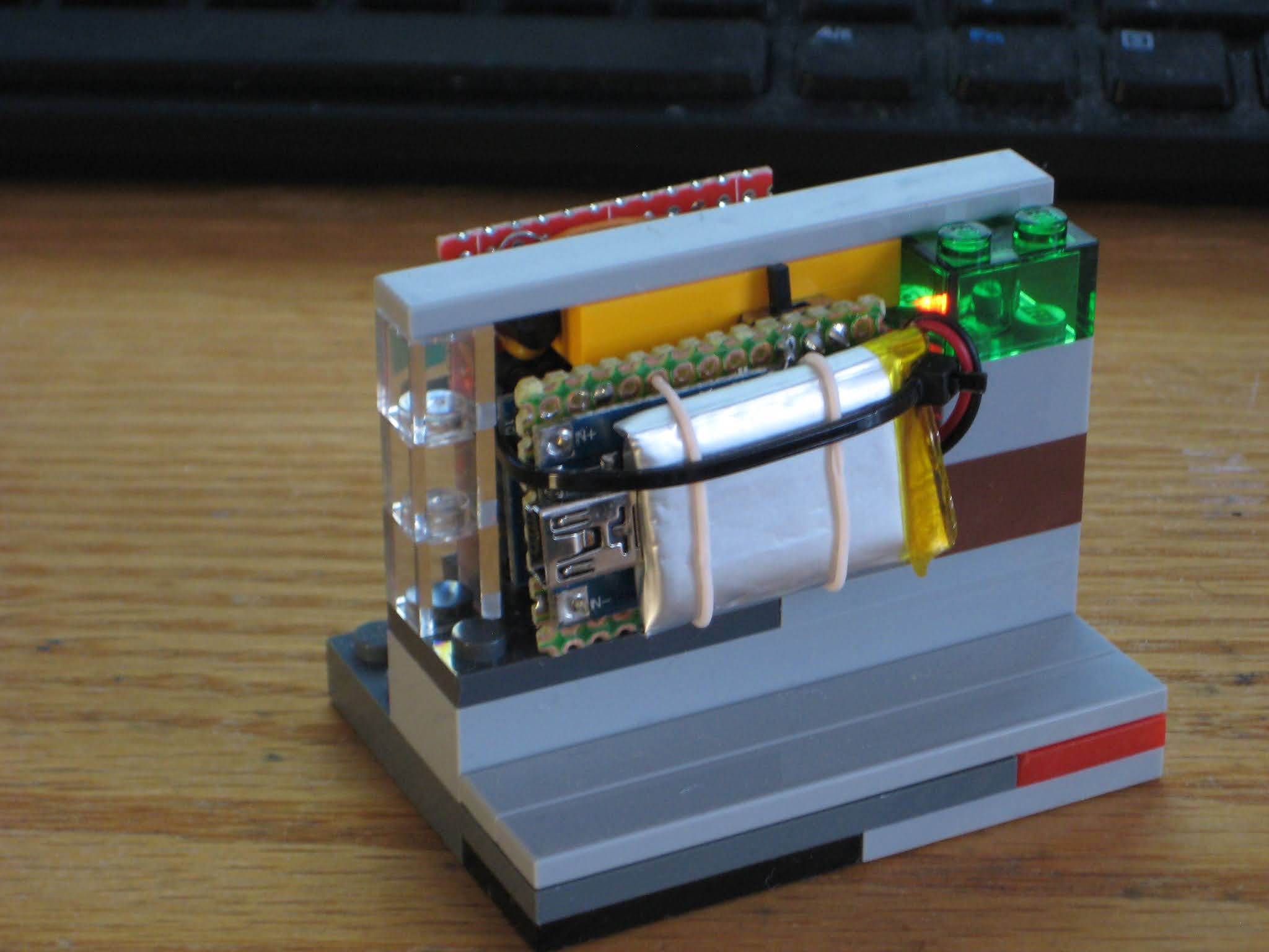
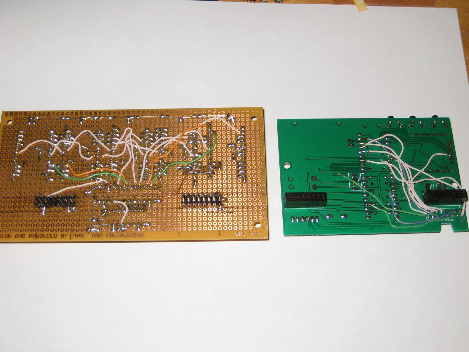
Below are some photos.
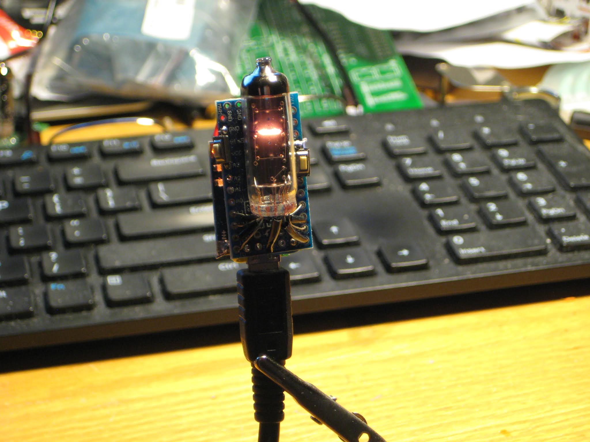


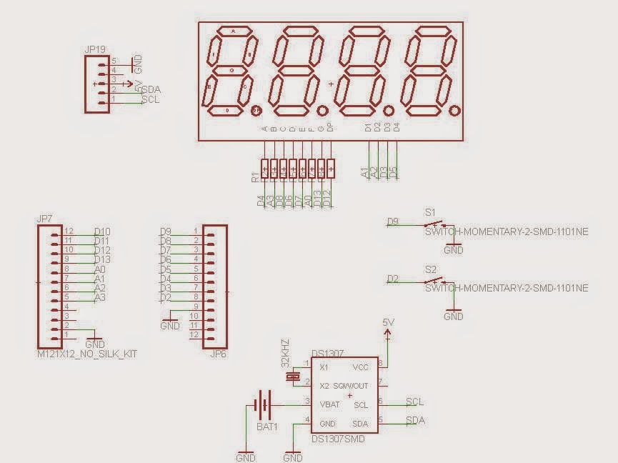
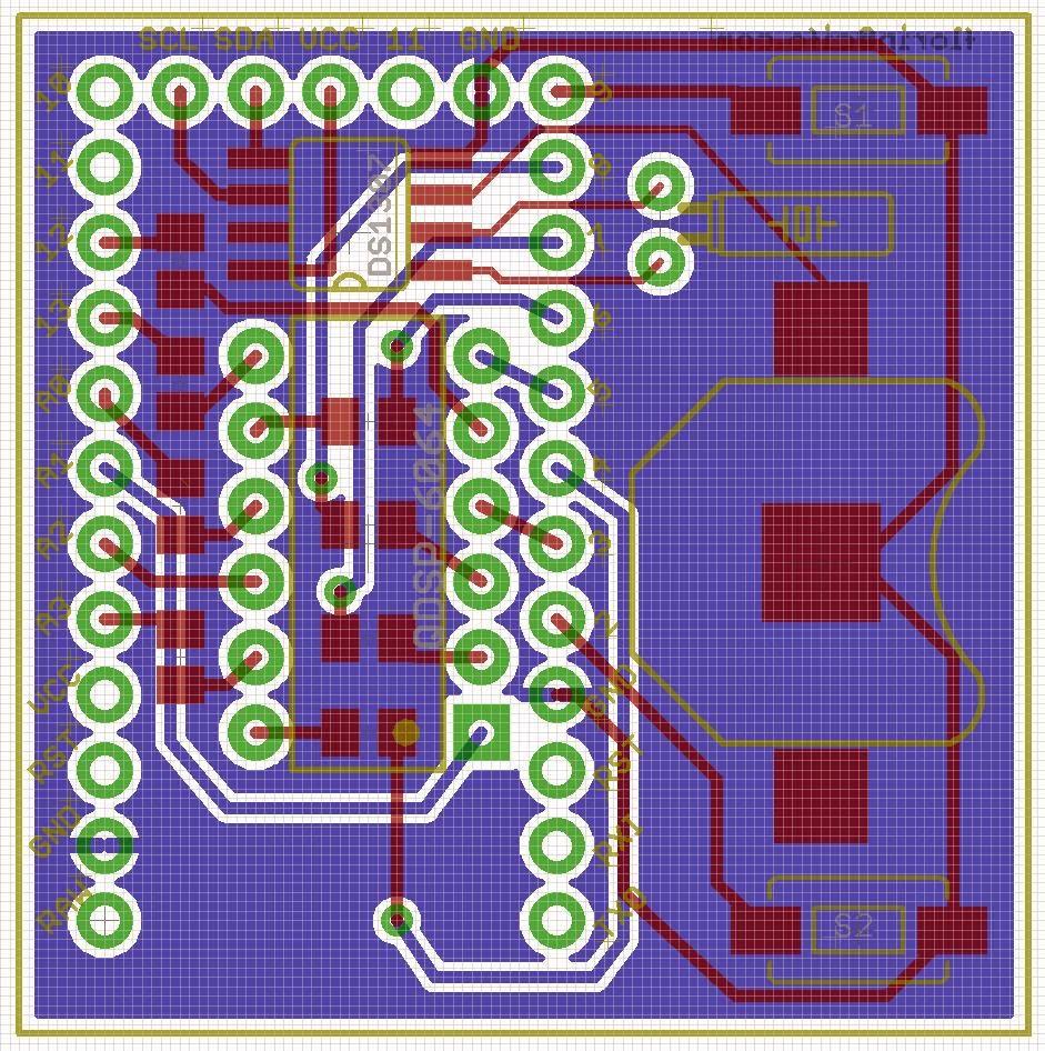
I was actually able to design the improvised RTC "shield" for ProMini shown in the above photo. Ordered from oshpark and shared here:

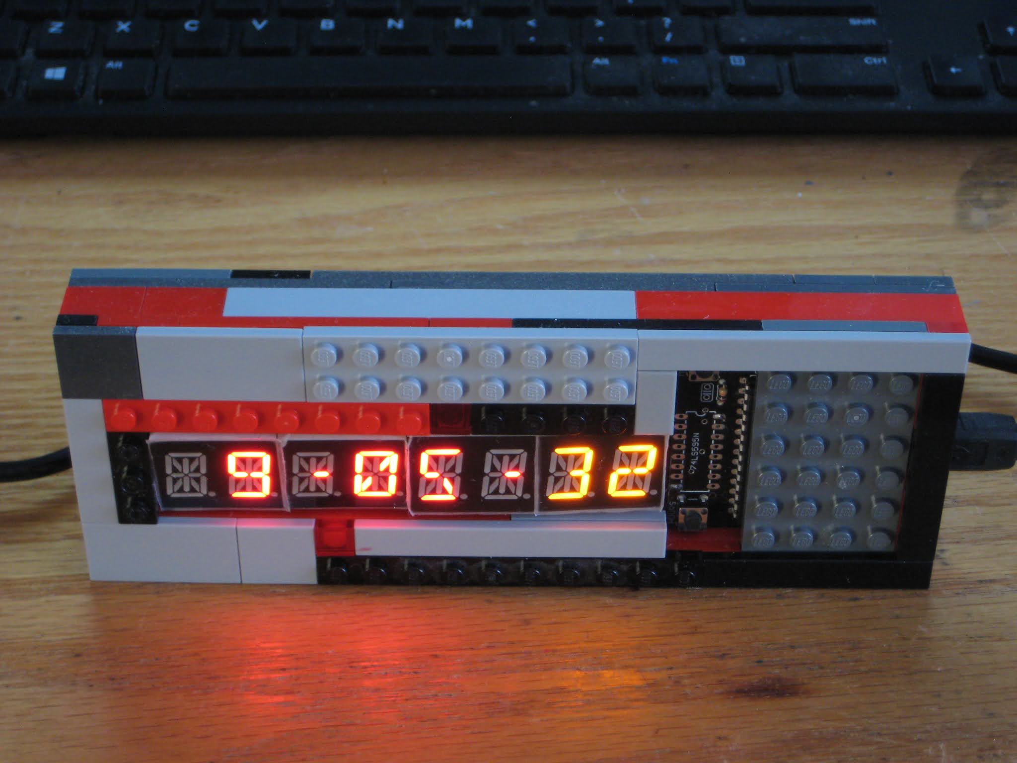
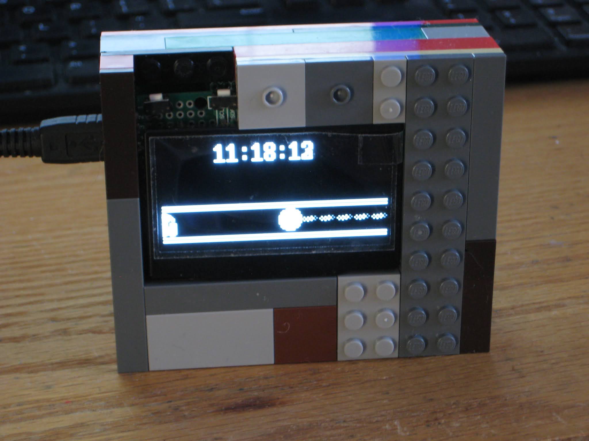
The "second" simplest single digit clock would be the one using a 7-segment LED display. It is the "second" simplest just because it requires 7 more current-limiting resistors. Otherwise, if the wiring (numitron tube and 7-segment display) is similar, the above code works with no changes (tried and proven).
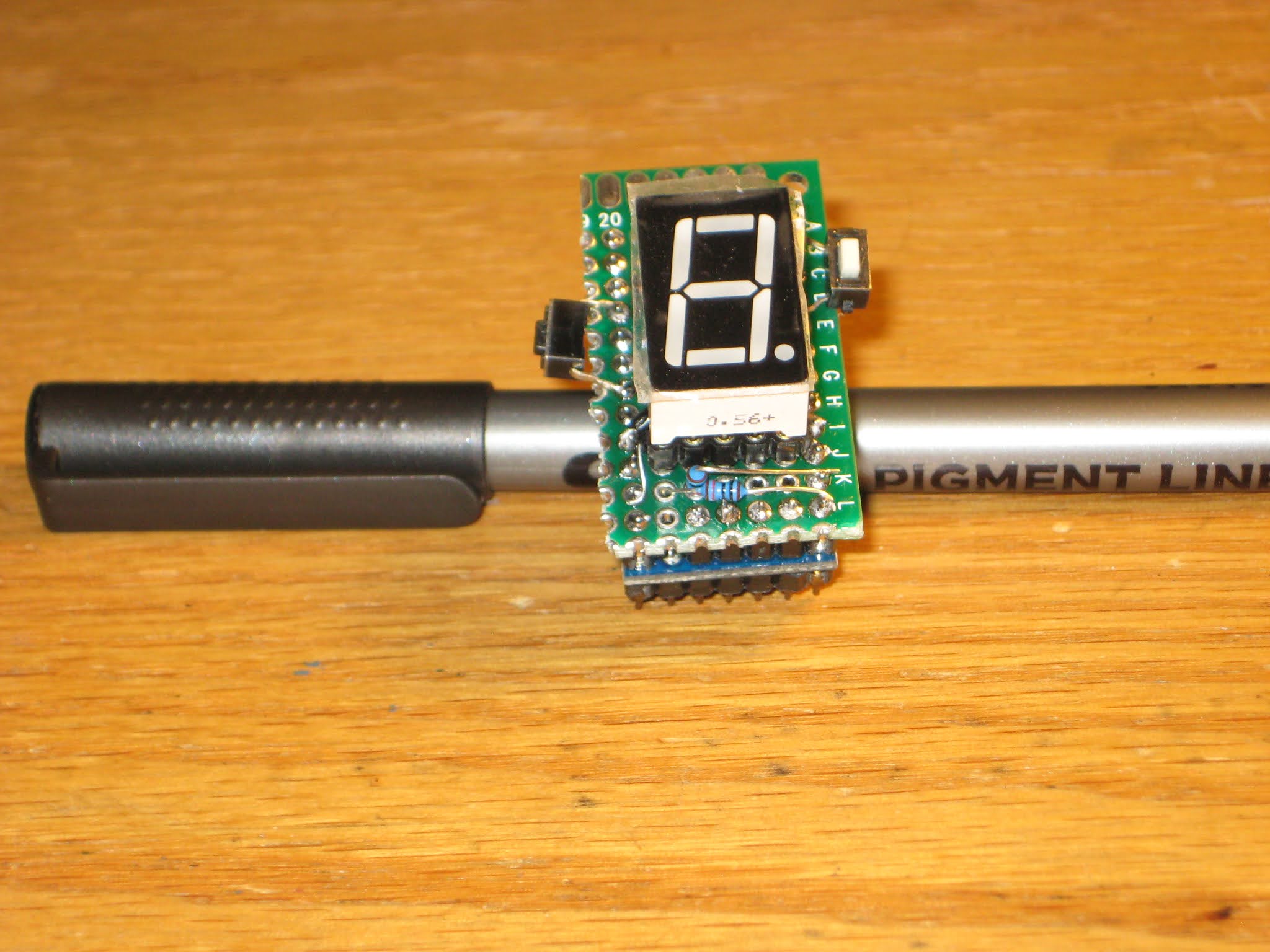
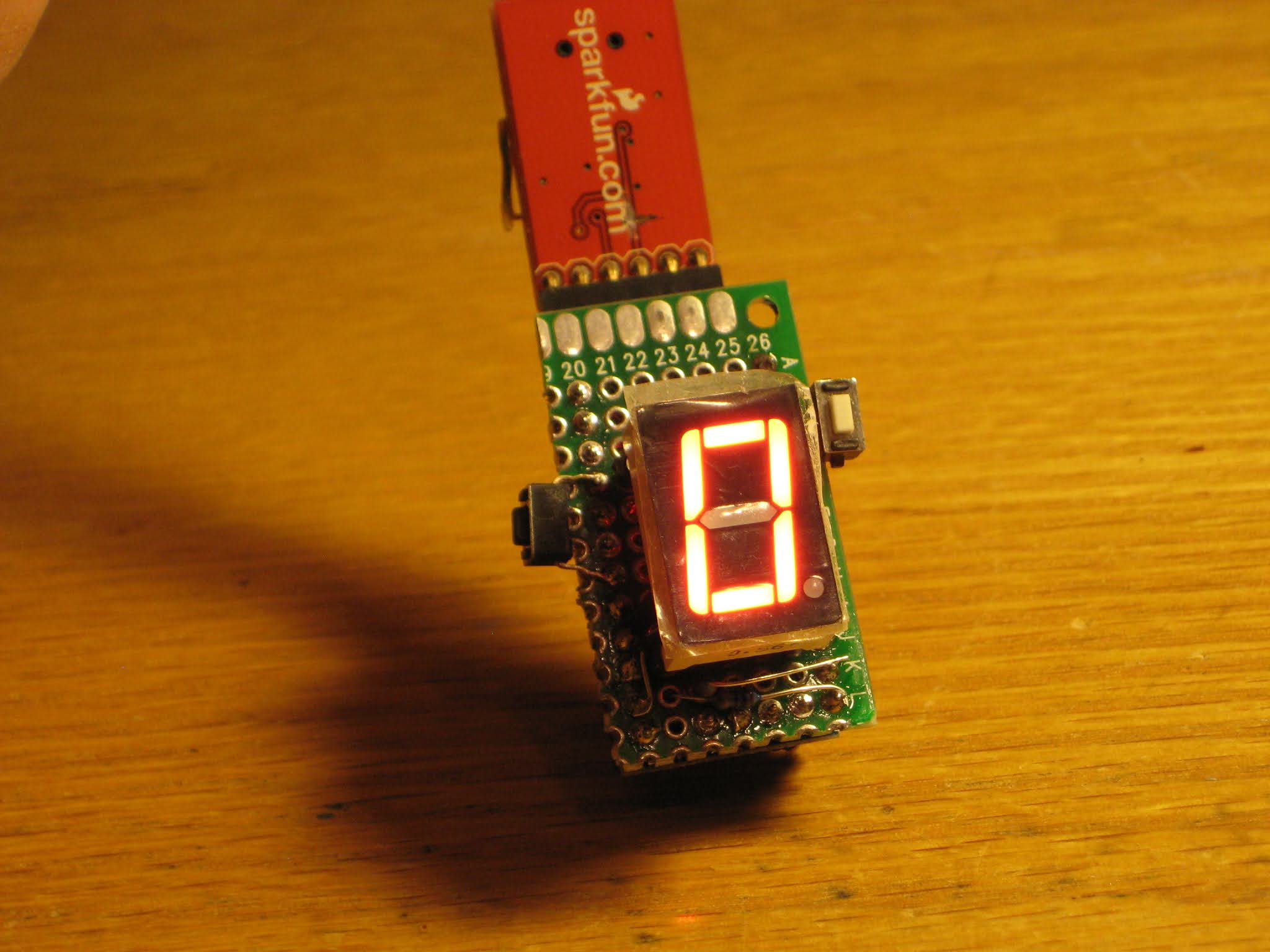
Shown above is another ProMini-based prototype of a single digit clock, without the RTC shield. I expect this single digit 7-segment clock to work with the LiPo battery shield (unlike the single numitron clock). Note that the display is common anode, with the anode wired to Vcc and each cathode connected to processor's outputs. The segment is lit when the output is grounded (set to digital 0), similar to the numitron's driving.