

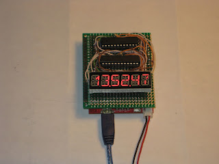
Prototype 14-segment-display shield
There are many ways (*) to drive the 6-digit 14-segment common cathode display from Seeed Studio.
This time I chose to multiplex two MAX7221, a method described here (but used to drive a bi-color 8x8 LED matrix).
The code is based on LedControl library, which I extended to cover the definition and display of 14-segment characters (digits, upper case letters, and a few specials). Below is a relevant fragment of the code I added:
/*
* Segment names in the 14-segment (plus DP) display:
*
* - A
* |\|/| F,I,J,K,B
* - - G,H
* |/|\| E,N,M,L,C
* - . D,P
*/
// my wiring:
// GFEDCBAx
// 1st byte: B11111111
//
// NHJIKMLP
// 2nd byte: B11111111
const static byte charTable14Seg[43][2] = {
{B01111110,B10001000}, // 0
{B00001100,B00001000}, // 1
{B10110110,B01000000}, // 2
{B00011110,B01000000}, // 3
{B11001100,B01000000}, // 4
{B11010010,B00000010}, // 5
{B11111010,B01000000}, // 6
{B00000010,B00001100}, // 7
{B11111110,B01000000}, // 8
{B11011110,B01000000}, // 9
{B00000000,B01000000}, // :
{B00000000,B01000000}, // ;
{B00000000,B01000000}, // <
{B00000000,B01000000}, // =
{B00000000,B01000000}, // >
{B00000000,B01000000}, // ?
{B00000000,B01000000}, // @
{B11101110,B01000000}, // A
{B00011110,B01100100}, // B
{B01110010,B00000000}, // C
{B00011110,B00100100}, // D
{B11110010,B01000000}, // E
{B11100010,B01000000}, // F
{B01111010,B01000000}, // G
{B11101100,B01000000}, // H
{B00000000,B00100100}, // I
{B00111100,B00000000}, // J
{B11100000,B00001010}, // K
{B01110000,B00000000}, // L
{B01101100,B00011000}, // M
{B01101100,B000100L0}, // N
{B01111110,B00000000}, // 0
{B11100110,B01000000}, // P
{B01111110,B00000010}, // Q
{B11100110,B01000010}, // R
{B11011010,B01000000}, // S
{B00000010,B00100100}, // T
{B01111100,B00000000}, // U
{B01100000,B10001000}, // V
{B01101100,B10000010}, // W
{B00000000,B10011010}, // X
{B00000000,B00011100}, // Y
{B00010010,B10001000}, // Z
};
...
void setChar14Seg(byte pos, byte ascii)
{
if (pos>7)
return;
if (ascii>90 || ascii<48)
return;
byte index = ascii - 48;
for(byte seg=0; seg < 8; seg++)
{
SetLed(SEG_AG, pos, seg, charTable14Seg[index][0] & 1 << seg);
SetLed(SEG_GN, pos, seg, charTable14Seg[index][1] & 1 << seg);
}
This method (hardware and software) can be used for up to 8 14/16-segment displays.
(*) Should be the topic of a future post.

This time I chose to multiplex two MAX7221, a method described here (but used to drive a bi-color 8x8 LED matrix).

The code is based on LedControl library, which I extended to cover the definition and display of 14-segment characters (digits, upper case letters, and a few specials). Below is a relevant fragment of the code I added:
/*
* Segment names in the 14-segment (plus DP) display:
*
* - A
* |\|/| F,I,J,K,B
* - - G,H
* |/|\| E,N,M,L,C
* - . D,P
*/
// my wiring:
// GFEDCBAx
// 1st byte: B11111111
//
// NHJIKMLP
// 2nd byte: B11111111
const static byte charTable14Seg[43][2] = {
{B01111110,B10001000}, // 0
{B00001100,B00001000}, // 1
{B10110110,B01000000}, // 2
{B00011110,B01000000}, // 3
{B11001100,B01000000}, // 4
{B11010010,B00000010}, // 5
{B11111010,B01000000}, // 6
{B00000010,B00001100}, // 7
{B11111110,B01000000}, // 8
{B11011110,B01000000}, // 9
{B00000000,B01000000}, // :
{B00000000,B01000000}, // ;
{B00000000,B01000000}, // <
{B00000000,B01000000}, // =
{B00000000,B01000000}, // >
{B00000000,B01000000}, // ?
{B00000000,B01000000}, // @
{B11101110,B01000000}, // A
{B00011110,B01100100}, // B
{B01110010,B00000000}, // C
{B00011110,B00100100}, // D
{B11110010,B01000000}, // E
{B11100010,B01000000}, // F
{B01111010,B01000000}, // G
{B11101100,B01000000}, // H
{B00000000,B00100100}, // I
{B00111100,B00000000}, // J
{B11100000,B00001010}, // K
{B01110000,B00000000}, // L
{B01101100,B00011000}, // M
{B01101100,B000100L0}, // N
{B01111110,B00000000}, // 0
{B11100110,B01000000}, // P
{B01111110,B00000010}, // Q
{B11100110,B01000010}, // R
{B11011010,B01000000}, // S
{B00000010,B00100100}, // T
{B01111100,B00000000}, // U
{B01100000,B10001000}, // V
{B01101100,B10000010}, // W
{B00000000,B10011010}, // X
{B00000000,B00011100}, // Y
{B00010010,B10001000}, // Z
};
...
void setChar14Seg(byte pos, byte ascii)
{
if (pos>7)
return;
if (ascii>90 || ascii<48)
return;
byte index = ascii - 48;
for(byte seg=0; seg < 8; seg++)
{
SetLed(SEG_AG, pos, seg, charTable14Seg[index][0] & 1 << seg);
SetLed(SEG_GN, pos, seg, charTable14Seg[index][1] & 1 << seg);
}
}
(*) Should be the topic of a future post.
[original story: Wise time with Arduino]