Posts with «mp3» label

Get Pumped for This Miniature Gym

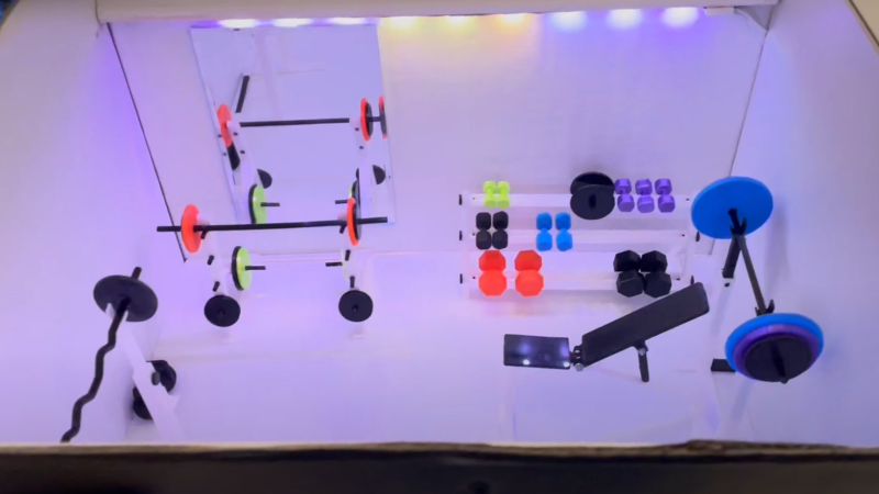
[Duncan McIntyre] lives in the UK but participated in a secret Santa gift exchange for his Dutch friends’ Sinterklaas celebration. In traditional maker fashion, [Duncan] went overboard and created a miniature gym gift box, complete with flashing lights, music and a motorized lid.

[Duncan] used [TanyaAkinora]’s 3D printed tiny gym to outfit the box with tiny equipment, with a tiny mirror added to round out the tiny room. An ATmega328P was used as the main microcontroller to drive the MP3 player module and A4988 stepper motor controller. The stepper motor was attached to a drawer slide via a GT2 timing belt and pulley to actuate the lid. Power is provided through an 18V, 2A power supply with an LM7805 providing power to the ATmega328P and supporting logical elements. As an extra flourish, [Duncan] added some hardware audio signal peak detection, fed from the speaker output, which was then sampled by the ATmega328P to be able to flash the lights in time with the playing music. A micro switch detects when the front miniature door is opened to begin the sequence of lights, song and lid opening.

[Duncan] provides source on GitHub for those curious about the Arduino code and schematics. We’re fans of miniature pieces of ephemera and we’ve featured projects ranging from tiny 3D printed tiny escalators to tiny arcade cabinets.

Video after the break!

Kids’ Jukebox Based on Arduino with RFID

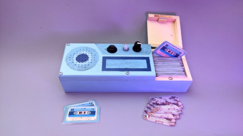
Consumer electronics aimed at young children tend to be quite janky and cheap-looking, and they often have to be to survive the extreme stress-testing normal use in this situation. You could buy a higher quality item intended for normal use, but this carries the risk of burning a hole in the pockets of the parents. To thread the needle on this dilemma for a child’s audiobook player, [Turi] built the Grimmboy for a relative of his.

Taking its name from the Brothers Grimm, the player is able of playing a number of children’s stories and fables in multiple languages, with each physically represented by a small cassette tape likeness with an RFID tag hidden in each one. A tape can be selected and placed in the player, and the Arduino at the center of it will recognize the tag and play the corresponding MP3 file stored locally on an SD card. There are simple controls and all the circuitry to support its lithium battery as well. All of the source code that [Turi] used to build this is available on the project’s GitHub page.

This was also featured at the Arudino blog as well, and we actually featured a similar project a while ago with a slightly different spin. Both are based on ideas from Tonuino, an open source project aimed at turning Arduinos into MP3 players. If you’re looking to build something with a few more features, though, take a look at this custom build based on the RP2040 microcontroller instead.

Hack a Day 17 Dec 06:00

Chest of Drawers Stores Audio Memories

Some people collect stamps, some collect barbed wire, and some people even collect little bits of silicon and plastic. But the charmingly named [videoschmideo] collects memories, mostly of his travels around the world with his wife. Trinkets and treasures are easy to keep track of, but he found that storing the audio clips he collects a bit more challenging. Until he built this audio memory chest, that is.

Granted, you might not be a collector of something as intangible as audio files, and even if you are, it seems like Google Drive or Dropbox might be the more sensible place to store them. But the sensible way isn’t always the best way, and we really like this idea. Starting with what looks like an old card catalog file — hands up if you’ve ever greedily eyed a defunct card catalog in a library and wondered if it would fit in your shop for parts storage — [videoschmideo] outfitted 16 drawers with sensors to detect when they’re opened. Two of the drawers were replaced by speaker grilles, and an SD card stores all the audio files. When a drawer is opened, a random clip from that memory is played while you look through the seashells, postcards, and what-have-yous. Extra points for using an old-school typewriter for the drawer labels, and for using old card catalog cards for the playlists.

This is a simple idea, but a powerful one, and we really like the execution here. This one manages to simultaneous put us in the mood for some world travel and a trip to a real library.


Filed under: misc hacks
Hack a Day 18 Sep 12:00

Cluephone for Partiers

[Sam Horne] adapted an old school landline phone to deliver clues to birthday party guests. When guests find a numerical clue, they type it into the keypad to hear  the next clue, which involves decoding some Morse code.

The phone consists of an Arduino Pro Mini, a MP3/WAV trigger, and the phone itself, of which the earpiece and keypad have been reused. [Sam] had to map out the keypad and solder leads connecting the various contact points of the phone’s PCB to the Arduino’s digital pins. He used a digitally-generated voice to generate the audio files, and employed the Keypad and Password Arduino libraries to deliver the audio clues.

This seems like a great project to do for a party of any age of attendee, though the keying speed is quick. Hopefully [Sam]’s guests have a high Morse WPM or are quick with the pen! For more keypad projects check out this custom shortcut keyboard and printing a flexible keyboard.


Filed under: Arduino Hacks
Hack a Day 26 Aug 09:00

Code Like an Egyptian

[Marcelo Maximiano’s] son had a school project. He and a team of students built “The Pyramid’s Secret“–an electronic board game using the Arduino Nano. [Marcelo] helped with the electronics, but the result is impressive and a great example of packaging an Arduino project. You can see a video of the game, below.

In addition to the processor, the game uses a WT5001M02 MP3 player (along with an audio amplifier) to produce music and voices. There’s also a rotary encoder, an LCD, a EEPROM (to hold the quiz questions and answers), and an LED driver. There’s also a bunch of LEDs, switches, and a wire maze that requires the player to navigate without bumping into the wire (think 2D Operation).

In addition to the code and hardware diagrams, there is a PDF file on GitHub describing more about the game. It is in Portuguese, though, so most of us will probably need a little translation help. However, a Brazillian site did have an English post about the game, which might be a good place to start.

You might not want to replicate the game, but it is a great example of how much an Arduino can do with some simple externals devices and some attention to packaging.

Sadly, most of our projects look more like this game (no offense to that hacker). Projects like this are way more likely to spark young people’s interest than a blinking LED or a capacitor meter. If you are more in the mood for arcade play, you can also check out Arduinocade.


Filed under: Arduino Hacks
Hack a Day 04 Dec 06:00
arduino  arduino hacks  egypt  game  mp3  pyramid  

Arduino based Security Project Using Cayenne


Description

This is an Arduino based home security project that uses the power of "Cayenne" for extraordinary capabilities.

Cayenne Beta

Cayenne is a new IoT drag and drop platform originally released for the Raspberry Pi, but now available for Arduino. Cayenne makes the task of connecting your Arduino to the internet as simple as possible. All of the complexity of internet connectivity is hidden within the Cayenne library.

You can easily create a Network of Arduinos and build an IoT system which can be managed and operated within the Cayenne dashboard. This dashboard is accessible through your browser or via the Cayenne smart phone app (on IOS or Android).

The feature I liked the most, was the ability to change the position of sensors or actuators on the Arduino without having to re-upload Arduino code. I could manage the changed position from within the Cayenne platform. The other feature that I liked was the ability to setup actions based on custom triggers. You can use Cayenne to trigger a whole range of functions, for example: play a sound, move a motor, light up an LED, or to send alert notifications via email or SMS.

Cayenne is in Beta at the moment, so there are a few minor bugs here and there, but overall - I give it a thumbs up - it is definitely worth checking out.
 

Here is a link to the Cayenne Beta Program:
**Cayenne Beta Link**


              Source: myDevices Media Kit


Home Security Project Summary

In order to fully experience this new IoT platform, I decided to create a project to really put it through its paces. This is what my Security Project will need:

  1. It will use two Arduinos, one connected to the internet via an Ethernet shield, and the other via WIFI.
  2. Two detectors - a PIR sensor and a laser trip wire.
  3. If the sensors are tripped, the person has 10 seconds to present an RFID tag to the Grove RFID reader:
    • If a valid RFID tag is SUCCESSFULLY presented within the time limit, a nice personalised greeting will be played to that person using a Grove - Serial MP3 player
    • If a valid RFID FAILS to be presented within the time limit, an Alarm will sound, and I will be notified of the intrusion via an SMS alert.
  4. The Cayenne dashboard will show the status of the sensors, and I will have full control over my security system via the web interface (or smartphone app).
  5. The sensors will be attached to a different Arduino to that of the Grove MP3 player and the RFID tag reader, which means that there will have to be some level of communication between the two Arduinos. In fact, the cross communication will be vital to the success of this project.


Project Video


Flow Diagrams:

Main Flow Diagram

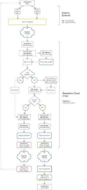
The following flow diagram shows the Security project process. It is a high level view of the decisions being made by each Arduino in response to various events.  


Triggers Flow Diagram

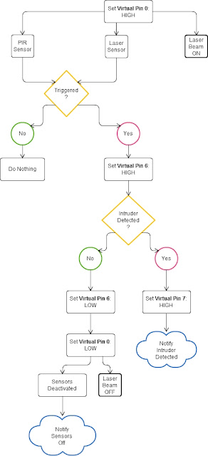
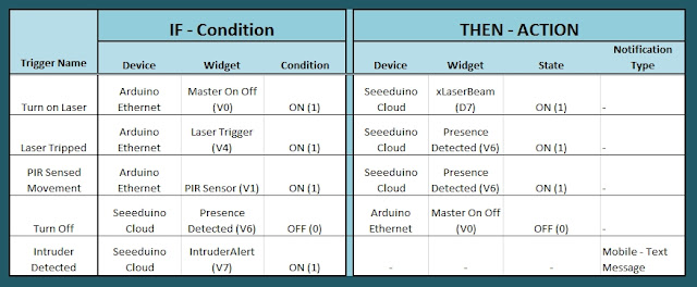
The following flow diagram aims to highlight the various triggers set up within Cayenne to get this Security system to work.  


Arduino IDE and Library Downloads

You will need an Arduino IDE to upload code to the Arduino and the Seeeduino Cloud.
Here is the link to the Arduino IDE: Arduino IDE - download location

The Cayenne service requires that you download and install the Cayenne Library into your Arduino IDE.
You can get the Cayenne Library from here: Cayenne Library File - Download


Cayenne Connectivity Setup

The Seeeduino Cloud needs to be prepared for use with Cayenne.
Normal operating/setup instructions can be found here: Seeeduino Cloud WIKI page
 
Once you have successfully connected Seeeduino Cloud to your WIFI network, you can add it to the Cayenne Dashboard by making the following selections from within the Cayenne Web application:

  1. Add New
  2. Device/Widget
  3. Microcontrollers
  4. Arduino
  5. Ensure Seeeduino Cloud is connected to WIFI network - the select the NEXT button
  6. Select - Arduino Yun: Built-in Ethernet - ticked
  7. Providing you have already installed the Cayenne library as described above - you should be able to copy and paste the code to the Arduino IDE and upload to the Seeeduino Cloud.
  8. If successful, you should see the Arduino Yun board appear within the Cayenne Dashboard. If not, then seek help within the Cayenne forum.


The Arduino UNO with WIZNET 5100 - Ethernet Shield
also needs to be prepared with Cayenne

  1. Add New
  2. Device/Widget
  3. Microcontrollers
  4. Arduino
  5. Ensure Arduino is powered, and Ethernet shield is connected to your internet router via an Ethernet cable
  6. Select - Arduino Uno: Ethernet Shield W5100 - ticked
  7. Copy and paste the code to the Arduino IDE and upload to the Arduino UNO.
  8. If successful, you should see the Arduino Uno board appear within the Cayenne Dashboard. If not, then seek help within the Cayenne forum.


If you have the Ethernet shield with the WIZNET 5200 chip, then you may need to download a specific Ethernet library in addition to the Cayenne library.
 
Just follow the instructions within the Automatically generated sketch provided - when you select your specific Arduino/Ethernet/WIFI shield combination. If you need further instructions on connecting your device to Cayenne - then please visit the myDevices website for the online documentation.


ARDUINO CODE (1)


Code for Arduino UNO with Ethernet Shield:

The following code will need to be uploaded to the Arduino UNO:


ARDUINO CODE (2)


Code for Seeeduino Cloud:

The following code will need to be uploaded to the Seeeduino Cloud:


Fritzing diagram (1)


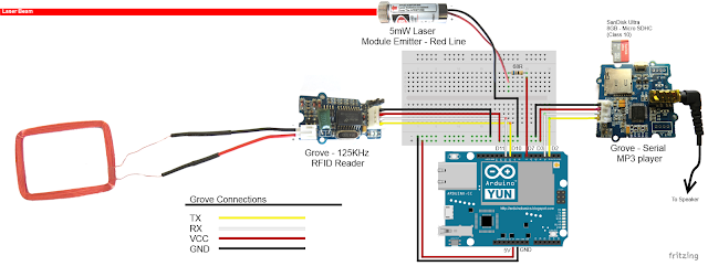
Fritzing diagram for Arduino UNO with Ethernet

Please click on the picture below for an enlarged version of this fritzing diagram


Fritzing diagram (2)


Fritzing diagram for Seeeduino Cloud

Please click on the picture below for an enlarged version of this fritzing diagram


Cayenne Dashboard Setup - GUI


The Arduino code only provides half of the functionality of this project. The Cayenne Dashboard needs to be setup to provide the rest of the functionality. The following instructions will show you how to add each of the widgets required for this Home Security project.


Arduino Ethernet - Master Switch

The master switch allows me to turn the security system on and off. When I turn the MASTER SWITCH ON, the laser beam will turn on, and the sensors will start monitoring the area for intruders. This widget is NOT associated with a physical switch/sensor on the Arduino - it uses virtual channel 0. We need to add the Master switch to the dashboard:


  1. Add New
  2. Device/Widget
  3. Actuators
  4. Generic
  5. Digital Output - Control a Digital Output
  6. Widget Name: Master On Off Switch
  7. Select Device: Arduino Ethernet
  8. Connectivity: Virtual
  9. Pin: V0
  10. Choose Widget: Button
  11. Choose Icon: Valve
  12. Step2: Add Actuator
We will add a trigger later to get this button to automatically turn the Laser beam on.


Arduino Ethernet - PIR Sensor

This sensor will be used to detect movement in the room. If a person walks into the room, this sensor will detect movement, and will trigger a message to be played on the Grove Serial MP3 player. The message will aim to get the person to identify themselves. They identify themselves by placing their RFID tag in close proximity to the Grove RFID reader. If the tag is valid, a "Welcome home" message is played on the Grove MP3 player. If a valid tag is not presented to the reader within 10 seconds, an Alarm will go off ("Alarm sound" played on Grove MP3 player.)

The PIR sensor is connected to digital Pin 6 of the Arduino, however, it is mapped to virtual pin 1 for better synchronisation with the Cayenne dashboard. This was done to capture ALL detections - as the PIR sensor could change from a LOW to HIGH and back to LOW state in between a Cayenne state check - and therefore, Cayenne could miss this motion detection.. Therefore we need to assign the PIR sensor to a virtual channel in the following way:
  1. Add New
  2. Device/Widget
  3. Sensors
  4. Motion
  5. Digital Motion Sensor - Motion Detector
  6. Widget Name: PIR sensor
  7. Select Device: Arduino Ethernet
  8. Connectivity: Virtual
  9. Pin: V1
  10. Choose Widget: 2-State Display
  11. Choose Icon: Light
  12. Step2: Add Sensor
  13. Select Settings from the PhotoResistor
  14. Choose Display: Value
  15. Save


Arduino Ethernet - Photoresistor

This sensor will be used with the laser beam to create a laser tripwire. If the sensor detects a change in light levels (drops below the threshold), it will activate the laser trigger button on the dashboard. The person will then be required to identify themselves etc etc (similar to the motion detection by the PIR sensor). The photoresistor widget will display the raw analog reading from the sensor (connected to A2), but is associated with virtual channel 2. I used a virtual channel for more control over this sensor. To add the Photoresistor to the dashboard:

  1. Add New
  2. Device/Widget
  3. Sensors
  4. Luminosity
  5. Photoresistor - Luminosity sensor
  6. Widget Name: PhotoResistor
  7. Select Device: Arduino Ethernet
  8. Connectivity: Virtual
  9. Pin: V2
  10. Choose Widget: Value
  11. Choose Icon: Light
  12. Step2: Add Sensor


Arduino Ethernet - Laser Trigger

The laser trigger is just an indicator that someone tripped the laser beam. The state of this widget is used to notify the Seeeduino that a presence has been detected. This widget is associated with virtual pin 4 on the Arduino UNO with Ethernet.

  1. Add New
  2. Device/Widget
  3. Actuators
  4. Generic
  5. Digital Output - Control a Digital Output
  6. Widget Name: Laser Trigger
  7. Select Device: Arduino Ethernet
  8. Connectivity: Virtual
  9. Pin: V4
  10. Choose Widget: Button
  11. Choose Icon: Lock
  12. Step2: Add Actuator


Arduino Ethernet - Laser Threshold

The laser threshold is used to manually configure the light level at which the laser trigger will trip. When the photoresistor value drops below the threshold value, the laser trigger icon will activate. This allows the threshold value to be updated from the Cayenne dashboard, rather than having to manually adjust the value in the Arduino code. Also, this threshold can be set remotely, in that you don't have to be near the Arduino to change this value. A very useful feature of this Security system. This widget is associated with virtual pin 5 on the Arduino UNO with Ethernet.

  1. Add New
  2. Device/Widget
  3. Actuators
  4. Generic
  5. PWM Output - Control a PWM Output
  6. Widget Name: Laser Threshold
  7. Select Device: Arduino Ethernet
  8. Connectivity: Virtual
  9. Pin: V5
  10. Choose Widget: Slider
  11. Slider Min Value: 0
  12. Slider Max Value: 10
  13. Step2: Add Actuator
The max value of the slider is 10 - due to a current bug in the Cayenne software. Once resolved, this value (as well as the relevant Arduino code) will need to be updated.


Seeeduino Cloud - Presence Detected

The presence detected widget is there to notify the Seeeduino Cloud that a presence has been detected on the Arduino Uno with Ethernet shield. When the PIR sensor detects movement or if the laser tripwire is tripped, Cayenne will change the state of the Presence Detected widget from LOW to HIGH. This is used within the Seeeduino Cloud to trigger the message "Place your keys on the Mat"
. If a valid RFID tag is read by the Grove RFID reader, then this widget's state will change back from HIGH to LOW, and the MasterSwitch will be deactivated - turning the Security system off. This widget is associated with Virtual pin 6 on the Seeeduino Cloud.

  1. Add New
  2. Device/Widget
  3. Actuators
  4. Generic
  5. Digital Output - Control a Digital Output
  6. Widget Name: Presence Detected
  7. Select Device: Seeeduino Cloud
  8. Connectivity: Virtual
  9. Pin: V6
  10. Choose Widget: Button
  11. Choose Icon: Lock
  12. Step2: Add Actuator


Seeeduino Cloud - Intruder Alert

If a valid RFID tag is not read by the Grove RFID reader within 10 seconds of a presence detection event, an alarm will sound, and this widget will be activated. This will trigger a notification event - to notify me of the unauthorised intrusion - via SMS or email. I will also have a visual indicator on the Cayenne dashboard that an intrusion has taken place. This widget is associated with Virtual pin 7 on the Seeeduino Cloud.

  1. Add New
  2. Device/Widget
  3. Actuators
  4. Generic
  5. Digital Output - Control a Digital Output
  6. Widget Name: Laser Trigger
  7. Select Device: Seeeduino Cloud
  8. Connectivity: Virtual
  9. Pin: V7
  10. Choose Widget: Button
  11. Choose Icon: Thermometer
  12. Step2: Add Actuator


Seeeduino Cloud - Laser Beam

The laser beam widget was created to allow for full control over the laser beam. The laser beam can be turned on or off from the Cayenne dashboard, and a connected to digital pin 7 on the Seeeduino Cloud.


  1. Add New
  2. Device/Widget
  3. Actuators
  4. Light
  5. Light Switch - Turn On/Off a Light
  6. Widget Name: xLaser Beam
  7. Select Device: Seeeduino Cloud
  8. Connectivity: Digital
  9. Pin: D7
  10. Choose Widget: Button
  11. Choose Icon: Light
  12. Step2: Add Actuator


Cayenne Triggers

Now that all of the widgets have been added to the Dashboard, there is just one more step to complete the Security System. We need to setup the triggers. These triggers provide a level of automation that is easy to create within Cayenne, but would be very complicated otherwise. I set my triggers up as per the table below. Each row represents one of the triggers within my Cayenne dashboard. If you would like to see an example of how to add a trigger - please have a look at the video at the top of this tutorial.  


Concluding comments

I used many different elements to put this home/office security project together - Multiple Arduinos were connected to the internet, both controlled by a web/smart phone app, cross-communication/synchronisation between the Arduinos, and the use of multiple sensors and modules including a laser beam !
 
This was way more than just a simple PIR sense and alarm project. I now have a personalised greeting and reminder system when I walk in the door. Everyone else has their own personalised greeting. I can enable my Security System remotely, from two blocks away, and if I wanted to - I could enable it from the other side of the world. I know instantly when someone has entered my house/office.... with an SMS alert straight to my phone.
 
This project could easily be extended:

  1. Press a button on my phone to manually trigger/play a specific message/sound/song
  2. Take a picture of the intruder
  3. Introduce fire or leak detection aswell
  4. Add other environmental sensors - Temperature / Humidity
  5. Connect it to lamp/light - creating a security light
I am sure you can think of more things I could do with this system. In fact, why don't you mention your ideas in the comments below.
 
Cayenne was instrumental in getting this project to work. I don't think I would know where to start if I had to do this project without this cool IoT platform. I think I will definitely be trying out a few more projects using Cayenne, and should you want to do the same, then please make sure to join Cayenne Beta:
 
Here is the link you need to get to the right place: Cayenne Beta Link


If you like this page, please do me a favour and show your appreciation :

 
Visit my ArduinoBasics Google + page.
Follow me on Twitter by looking for ScottC @ArduinoBasics.
I can also be found on Pinterest and Instagram.
Have a look at my videos on my YouTube channel.


ScottC 02 Sep 05:11
alarm  arduino  arduinobasics  cayenne  laser  mp3  mydevices  pir  rfid  security  sms  tutorial  

Arduino based Security Project Using Cayenne


Description

This is an Arduino based home security project that uses the power of "Cayenne" for extraordinary capabilities.

Cayenne Beta

Cayenne is a new IoT drag and drop platform originally released for the Raspberry Pi, but now available for Arduino. Cayenne makes the task of connecting your Arduino to the internet as simple as possible. All of the complexity of internet connectivity is hidden within the Cayenne library.

You can easily create a Network of Arduinos and build an IoT system which can be managed and operated within the Cayenne dashboard. This dashboard is accessible through your browser or via the Cayenne smart phone app (on IOS or Android).

The feature I liked the most, was the ability to change the position of sensors or actuators on the Arduino without having to re-upload Arduino code. I could manage the changed position from within the Cayenne platform. The other feature that I liked was the ability to setup actions based on custom triggers. You can use Cayenne to trigger a whole range of functions, for example: play a sound, move a motor, light up an LED, or to send alert notifications via email or SMS.

Cayenne is in Beta at the moment, so there are a few minor bugs here and there, but overall - I give it a thumbs up - it is definitely worth checking out.
 

Here is a link to the Cayenne Beta Program:
**Cayenne Beta Link**


              Source: myDevices Media Kit


Home Security Project Summary

In order to fully experience this new IoT platform, I decided to create a project to really put it through its paces. This is what my Security Project will need:

  1. It will use two Arduinos, one connected to the internet via an Ethernet shield, and the other via WIFI.
  2. Two detectors - a PIR sensor and a laser trip wire.
  3. If the sensors are tripped, the person has 10 seconds to present an RFID tag to the Grove RFID reader:
    • If a valid RFID tag is SUCCESSFULLY presented within the time limit, a nice personalised greeting will be played to that person using a Grove - Serial MP3 player
    • If a valid RFID FAILS to be presented within the time limit, an Alarm will sound, and I will be notified of the intrusion via an SMS alert.
  4. The Cayenne dashboard will show the status of the sensors, and I will have full control over my security system via the web interface (or smartphone app).
  5. The sensors will be attached to a different Arduino to that of the Grove MP3 player and the RFID tag reader, which means that there will have to be some level of communication between the two Arduinos. In fact, the cross communication will be vital to the success of this project.


Project Video


Flow Diagrams:

Main Flow Diagram

The following flow diagram shows the Security project process. It is a high level view of the decisions being made by each Arduino in response to various events.  


Triggers Flow Diagram

The following flow diagram aims to highlight the various triggers set up within Cayenne to get this Security system to work.  


Arduino IDE and Library Downloads

You will need an Arduino IDE to upload code to the Arduino and the Seeeduino Cloud.
Here is the link to the Arduino IDE: Arduino IDE - download location

The Cayenne service requires that you download and install the Cayenne Library into your Arduino IDE.
You can get the Cayenne Library from here: Cayenne Library File - Download


Cayenne Connectivity Setup

The Seeeduino Cloud needs to be prepared for use with Cayenne.
Normal operating/setup instructions can be found here: Seeeduino Cloud WIKI page
 
Once you have successfully connected Seeeduino Cloud to your WIFI network, you can add it to the Cayenne Dashboard by making the following selections from within the Cayenne Web application:

  1. Add New
  2. Device/Widget
  3. Microcontrollers
  4. Arduino
  5. Ensure Seeeduino Cloud is connected to WIFI network - the select the NEXT button
  6. Select - Arduino Yun: Built-in Ethernet - ticked
  7. Providing you have already installed the Cayenne library as described above - you should be able to copy and paste the code to the Arduino IDE and upload to the Seeeduino Cloud.
  8. If successful, you should see the Arduino Yun board appear within the Cayenne Dashboard. If not, then seek help within the Cayenne forum.


The Arduino UNO with WIZNET 5100 - Ethernet Shield
also needs to be prepared with Cayenne

  1. Add New
  2. Device/Widget
  3. Microcontrollers
  4. Arduino
  5. Ensure Arduino is powered, and Ethernet shield is connected to your internet router via an Ethernet cable
  6. Select - Arduino Uno: Ethernet Shield W5100 - ticked
  7. Copy and paste the code to the Arduino IDE and upload to the Arduino UNO.
  8. If successful, you should see the Arduino Uno board appear within the Cayenne Dashboard. If not, then seek help within the Cayenne forum.


If you have the Ethernet shield with the WIZNET 5200 chip, then you may need to download a specific Ethernet library in addition to the Cayenne library.
 
Just follow the instructions within the Automatically generated sketch provided - when you select your specific Arduino/Ethernet/WIFI shield combination. If you need further instructions on connecting your device to Cayenne - then please visit the myDevices website for the online documentation.


ARDUINO CODE (1)


Code for Arduino UNO with Ethernet Shield:

The following code will need to be uploaded to the Arduino UNO:


ARDUINO CODE (2)


Code for Seeeduino Cloud:

The following code will need to be uploaded to the Seeeduino Cloud:


Fritzing diagram (1)


Fritzing diagram for Arduino UNO with Ethernet

Please click on the picture below for an enlarged version of this fritzing diagram


Fritzing diagram (2)


Fritzing diagram for Seeeduino Cloud

Please click on the picture below for an enlarged version of this fritzing diagram


Cayenne Dashboard Setup - GUI


The Arduino code only provides half of the functionality of this project. The Cayenne Dashboard needs to be setup to provide the rest of the functionality. The following instructions will show you how to add each of the widgets required for this Home Security project.


Arduino Ethernet - Master Switch

The master switch allows me to turn the security system on and off. When I turn the MASTER SWITCH ON, the laser beam will turn on, and the sensors will start monitoring the area for intruders. This widget is NOT associated with a physical switch/sensor on the Arduino - it uses virtual channel 0. We need to add the Master switch to the dashboard:


  1. Add New
  2. Device/Widget
  3. Actuators
  4. Generic
  5. Digital Output - Control a Digital Output
  6. Widget Name: Master On Off Switch
  7. Select Device: Arduino Ethernet
  8. Connectivity: Virtual
  9. Pin: V0
  10. Choose Widget: Button
  11. Choose Icon: Valve
  12. Step2: Add Actuator
We will add a trigger later to get this button to automatically turn the Laser beam on.


Arduino Ethernet - PIR Sensor

This sensor will be used to detect movement in the room. If a person walks into the room, this sensor will detect movement, and will trigger a message to be played on the Grove Serial MP3 player. The message will aim to get the person to identify themselves. They identify themselves by placing their RFID tag in close proximity to the Grove RFID reader. If the tag is valid, a "Welcome home" message is played on the Grove MP3 player. If a valid tag is not presented to the reader within 10 seconds, an Alarm will go off ("Alarm sound" played on Grove MP3 player.)

The PIR sensor is connected to digital Pin 6 of the Arduino, however, it is mapped to virtual pin 1 for better synchronisation with the Cayenne dashboard. This was done to capture ALL detections - as the PIR sensor could change from a LOW to HIGH and back to LOW state in between a Cayenne state check - and therefore, Cayenne could miss this motion detection.. Therefore we need to assign the PIR sensor to a virtual channel in the following way:
  1. Add New
  2. Device/Widget
  3. Sensors
  4. Motion
  5. Digital Motion Sensor - Motion Detector
  6. Widget Name: PIR sensor
  7. Select Device: Arduino Ethernet
  8. Connectivity: Virtual
  9. Pin: V1
  10. Choose Widget: 2-State Display
  11. Choose Icon: Light
  12. Step2: Add Sensor
  13. Select Settings from the PhotoResistor
  14. Choose Display: Value
  15. Save


Arduino Ethernet - Photoresistor

This sensor will be used with the laser beam to create a laser tripwire. If the sensor detects a change in light levels (drops below the threshold), it will activate the laser trigger button on the dashboard. The person will then be required to identify themselves etc etc (similar to the motion detection by the PIR sensor). The photoresistor widget will display the raw analog reading from the sensor (connected to A2), but is associated with virtual channel 2. I used a virtual channel for more control over this sensor. To add the Photoresistor to the dashboard:

  1. Add New
  2. Device/Widget
  3. Sensors
  4. Luminosity
  5. Photoresistor - Luminosity sensor
  6. Widget Name: PhotoResistor
  7. Select Device: Arduino Ethernet
  8. Connectivity: Virtual
  9. Pin: V2
  10. Choose Widget: Value
  11. Choose Icon: Light
  12. Step2: Add Sensor


Arduino Ethernet - Laser Trigger

The laser trigger is just an indicator that someone tripped the laser beam. The state of this widget is used to notify the Seeeduino that a presence has been detected. This widget is associated with virtual pin 4 on the Arduino UNO with Ethernet.

  1. Add New
  2. Device/Widget
  3. Actuators
  4. Generic
  5. Digital Output - Control a Digital Output
  6. Widget Name: Laser Trigger
  7. Select Device: Arduino Ethernet
  8. Connectivity: Virtual
  9. Pin: V4
  10. Choose Widget: Button
  11. Choose Icon: Lock
  12. Step2: Add Actuator


Arduino Ethernet - Laser Threshold

The laser threshold is used to manually configure the light level at which the laser trigger will trip. When the photoresistor value drops below the threshold value, the laser trigger icon will activate. This allows the threshold value to be updated from the Cayenne dashboard, rather than having to manually adjust the value in the Arduino code. Also, this threshold can be set remotely, in that you don't have to be near the Arduino to change this value. A very useful feature of this Security system. This widget is associated with virtual pin 5 on the Arduino UNO with Ethernet.

  1. Add New
  2. Device/Widget
  3. Actuators
  4. Generic
  5. PWM Output - Control a PWM Output
  6. Widget Name: Laser Threshold
  7. Select Device: Arduino Ethernet
  8. Connectivity: Virtual
  9. Pin: V5
  10. Choose Widget: Slider
  11. Slider Min Value: 0
  12. Slider Max Value: 10
  13. Step2: Add Actuator
The max value of the slider is 10 - due to a current bug in the Cayenne software. Once resolved, this value (as well as the relevant Arduino code) will need to be updated.


Seeeduino Cloud - Presence Detected

The presence detected widget is there to notify the Seeeduino Cloud that a presence has been detected on the Arduino Uno with Ethernet shield. When the PIR sensor detects movement or if the laser tripwire is tripped, Cayenne will change the state of the Presence Detected widget from LOW to HIGH. This is used within the Seeeduino Cloud to trigger the message "Place your keys on the Mat"
. If a valid RFID tag is read by the Grove RFID reader, then this widget's state will change back from HIGH to LOW, and the MasterSwitch will be deactivated - turning the Security system off. This widget is associated with Virtual pin 6 on the Seeeduino Cloud.

  1. Add New
  2. Device/Widget
  3. Actuators
  4. Generic
  5. Digital Output - Control a Digital Output
  6. Widget Name: Presence Detected
  7. Select Device: Seeeduino Cloud
  8. Connectivity: Virtual
  9. Pin: V6
  10. Choose Widget: Button
  11. Choose Icon: Lock
  12. Step2: Add Actuator


Seeeduino Cloud - Intruder Alert

If a valid RFID tag is not read by the Grove RFID reader within 10 seconds of a presence detection event, an alarm will sound, and this widget will be activated. This will trigger a notification event - to notify me of the unauthorised intrusion - via SMS or email. I will also have a visual indicator on the Cayenne dashboard that an intrusion has taken place. This widget is associated with Virtual pin 7 on the Seeeduino Cloud.

  1. Add New
  2. Device/Widget
  3. Actuators
  4. Generic
  5. Digital Output - Control a Digital Output
  6. Widget Name: Laser Trigger
  7. Select Device: Seeeduino Cloud
  8. Connectivity: Virtual
  9. Pin: V7
  10. Choose Widget: Button
  11. Choose Icon: Thermometer
  12. Step2: Add Actuator


Seeeduino Cloud - Laser Beam

The laser beam widget was created to allow for full control over the laser beam. The laser beam can be turned on or off from the Cayenne dashboard, and a connected to digital pin 7 on the Seeeduino Cloud.


  1. Add New
  2. Device/Widget
  3. Actuators
  4. Light
  5. Light Switch - Turn On/Off a Light
  6. Widget Name: xLaser Beam
  7. Select Device: Seeeduino Cloud
  8. Connectivity: Digital
  9. Pin: D7
  10. Choose Widget: Button
  11. Choose Icon: Light
  12. Step2: Add Actuator


Cayenne Triggers

Now that all of the widgets have been added to the Dashboard, there is just one more step to complete the Security System. We need to setup the triggers. These triggers provide a level of automation that is easy to create within Cayenne, but would be very complicated otherwise. I set my triggers up as per the table below. Each row represents one of the triggers within my Cayenne dashboard. If you would like to see an example of how to add a trigger - please have a look at the video at the top of this tutorial.  


Concluding comments

I used many different elements to put this home/office security project together - Multiple Arduinos were connected to the internet, both controlled by a web/smart phone app, cross-communication/synchronisation between the Arduinos, and the use of multiple sensors and modules including a laser beam !
 
This was way more than just a simple PIR sense and alarm project. I now have a personalised greeting and reminder system when I walk in the door. Everyone else has their own personalised greeting. I can enable my Security System remotely, from two blocks away, and if I wanted to - I could enable it from the other side of the world. I know instantly when someone has entered my house/office.... with an SMS alert straight to my phone.
 
This project could easily be extended:

  1. Press a button on my phone to manually trigger/play a specific message/sound/song
  2. Take a picture of the intruder
  3. Introduce fire or leak detection aswell
  4. Add other environmental sensors - Temperature / Humidity
  5. Connect it to lamp/light - creating a security light
I am sure you can think of more things I could do with this system. In fact, why don't you mention your ideas in the comments below.
 
Cayenne was instrumental in getting this project to work. I don't think I would know where to start if I had to do this project without this cool IoT platform. I think I will definitely be trying out a few more projects using Cayenne, and should you want to do the same, then please make sure to join Cayenne Beta:
 
Here is the link you need to get to the right place: Cayenne Beta Link


If you like this page, please do me a favour and show your appreciation :

 
Visit my ArduinoBasics Google + page.
Follow me on Twitter by looking for ScottC @ArduinoBasics.
I can also be found on Pinterest and Instagram.
Have a look at my videos on my YouTube channel.


ScottC 30 Aug 15:42
alarm  arduino  arduinobasics  cayenne  laser  mp3  mydevices  pir  rfid  security  sms  tutorial  

Arduino BeatBox

Create your very own Arduino BeatBox !

Home-made capacitive touch sensors are used to trigger the MP3 drum sounds stored on the Grove Serial MP3 player. I have used a number of tricks to get the most out of this module, and I was quite impressed on how well it did. Over 130 sounds were loaded onto the SDHC card. Most were drum sounds, but I added some farm animal noises to provide an extra element of surprise and entertainment. You can put any sounds you want on the module and play them back quickly. We'll put the Grove Serial MP3 module through it's paces and make it into a neat little BeatBox !!


Key learning objectives

  • How to make your own beatbox
  • How to make capacitive drum pad sensors without using resistors
  • How to speed up Arduino's Analog readings for better performance
  • How to generate random numbers on your Arduino


Parts Required:

Making the drum pads


Fritzing Sketch


Grove Connections


Grove Connections (without base shield)


Arduino Sketch


  1
2
3
4
5
6
7
8
9
10
11
12
13
14
15
16
17
18
19
20
21
22
23
24
25
26
27
28
29
30
31
32
33
34
35
36
37
38
39
40
41
42
43
44
45
46
47
48
49
50
51
52
53
54
55
56
57
58
59
60
61
62
63
64
65
66
67
68
69
70
71
72
73
74
75
76
77
78
79
80
81
82
83
84
85
86
87
88
89
90
91
92
93
94
95
96
97
98
99
100
101
102
103
104
105
106
107
108
109
110
111
112
113
114
115
116
117
118
119
120
121
122
123
124
125
126
127
128
129
130
131
132
133
134
135
136
137
138
139
140
141
142
143
144
145
146
147
148
149
150
151
152
153
154
155
156
157
158
159
160
161
162
163
164
165
166
167
168
169
170
171
172
173
174
175
176
177
178
179
180
181
182
183
184
185
186
187
188
189
190
191
192
193
194
195
196
197
198
199
200
201
202
203
204
205
206
207
208
209
210
211
212
213
214
215
216
217
218
219
220
221
222
223
224
225
226
227
228
229
230
231
232
233
234
235
236
237
238
239

/* =================================================================================================
      Project: Arduino Beatbox
       Author: Scott C
      Created: 9th April 2015
  Arduino IDE: 1.6.2
      Website: http://arduinobasics.blogspot.com/p/arduino-basics-projects-page.html
  Description: This project uses home made capacitive sensors to trigger over 130 MP3 sounds
               on the Grove Serial MP3 player. 
               
               The ADCTouch library is used to eliminate the resistors from the Capacitive sensing circuit. 
               The code used for capacitive sensing was adapted from the ADCTouch library example sketches. 
               You can find the ADCTouch library and relevant example code here:
               http://playground.arduino.cc/Code/ADCTouch
               
               "Advanced Arduino ADC" is used to improve the analogRead() speed, and enhance the
               drum pad or capacitive sensor response time. The Advanced Arduino ADC code 
               was adapted from this site:
               http://www.microsmart.co.za/technical/2014/03/01/advanced-arduino-adc/
               
               
=================================================================================================== */
  #include <ADCTouch.h>
  #include <SoftwareSerial.h>
  
  
  //Global variables
  //===================================================================================================
  int potPin = A4; //Grove Sliding potentiometer is connected to Analog Pin 4
  int potVal = 0;
  byte mp3Vol = 0; //Variable used to control the volume of the MP3 player
  byte oldVol = 0;
  
  int buttonPin = 5; //Grove Button is connected to Digital Pin 5
  int buttonStatus = 0;
  
  byte SongNum[4] = {0x01,0x02,0x03,0x04}; //The first 4 songs will be assigned to the drum pads upon initialisation
  byte numOfSongs = 130; //Total number of MP3 songs/sounds loaded onto the SDHC card
  
  long randNumber; //Variable used to hold the random number - used to randomise the sounds.
  
  int ledState[4]; //Used to keep track of the status of all LEDs (on or off)
  int counter = 0;
  
  SoftwareSerial mp3(3, 4); // The Grove MP3 Player is connected to Arduino digital Pin 3 and 4 (Serial communication)
       
  int ref0, ref1, ref2, ref3; //reference values to remove offset
  int threshold = 100;
      
  // Define the ADC prescalers
  const unsigned char PS_64 = (1 << ADPS2) | (1 << ADPS1);
  const unsigned char PS_128 = (1 << ADPS2) | (1 << ADPS1) | (1 << ADPS0);


  //Setup()
  //===================================================================================================
  void setup(){
    //Initialise the Grove MP3 Module
    delay(2500); //Allow the MP3 module to power up
    mp3.begin(9600); //Begin Serial communication with the MP3 module
    setPlayMode(0x00);                        //0x00 = Single song - played once ie. not repeated. (default)
    
    //Define the Grove Button as an INPUT
    pinMode(buttonPin, INPUT);
    
    //Define the 4 LED Pins as OUTPUTs
    pinMode(8, OUTPUT); //Green LED
    pinMode(9, OUTPUT); //Blue LED
    pinMode(10, OUTPUT); //Red LED
    pinMode(11, OUTPUT); //Yellow LED
    
    //Make sure each LED is OFF, and store the state of the LED into a variable.
    for(int i=8;i<12;i++){
      digitalWrite(i, LOW);
      ledState[i-8]=0;
    } 
    
    //Double our clock speed from 125 kHz to 250 kHz
    ADCSRA &= ~PS_128;   // set up the ADC
    ADCSRA |= PS_64;    // set our own prescaler to 64
    
    //Create reference values to account for the capacitance of each pad.
    ref0 = ADCTouch.read(A0, 500);
    ref1 = ADCTouch.read(A1, 500); //Take 500 readings
    ref2 = ADCTouch.read(A2, 500);
    ref3 = ADCTouch.read(A3, 500);
    
     //This helps to randomise the drum pads.
     randomSeed(analogRead(0));
  }


  // Loop()
  //===================================================================================================
  void loop(){
     
    //Take a reading from the Grove Sliding Potentiometer, and set volume accordingly
    potVal = analogRead(potPin);
    mp3Vol = map(potVal, 0, 1023, 0,31); // Convert the potentometer reading (0 - 1023) to fit within the MP3 player's Volume range (0 - 31)
    if((mp3Vol>(oldVol+1))|(mp3Vol<(oldVol-1))){ // Only make a change to the Volume on the Grove MP3 player when the potentiometer value changes
      oldVol = mp3Vol;
      setVolume(mp3Vol);
      delay(10); // This delay is necessary with Serial communication to MP3 player
    }
    
    //Take a reading from the Pin attached to the Grove Button. If pressed, randomise the MP3 songs/sounds for each drum pad, and make the LEDs blink randomly.
    buttonStatus = digitalRead(buttonPin);
    if(buttonStatus==HIGH){
      SongNum[0]=randomSongChooser(1, 30);
      SongNum[1]=randomSongChooser(31, 60);
      SongNum[2]=randomSongChooser(61, 86);
      SongNum[3]=randomSongChooser(87, (int)numOfSongs);
      randomLEDBlink();
    }
    
    //Get the capacitive readings from each drum pad: 50 readings are taken from each pad. (default is 100)
    int value0 = ADCTouch.read(A0,50); // Green drum pad
    int value1 = ADCTouch.read(A1,50); // Blue drum pad
    int value2 = ADCTouch.read(A2,50); // Red drum pad
    int value3 = ADCTouch.read(A3,50); // Yellow drum pad
    
    //Remove the offset to account for the baseline capacitance of each pad.
    value0 -= ref0;       
    value1 -= ref1;
    value2 -= ref2;
    value3 -= ref3;
    
    
    //If any of the values exceed the designated threshold, then play the song/sound associated with that drum pad.
    //The associated LED will stay on for the whole time the drum pad is pressed, providing the value remains above the threshold.
    //The LED will turn off when the pad is not being touched or pressed.
    if(value0>threshold){
      digitalWrite(8, HIGH);
      playSong(00,SongNum[0]);
    }else{
      digitalWrite(8,LOW);
    }
    
    if(value1>threshold){
      digitalWrite(9, HIGH);
      playSong(00,SongNum[1]);
    }else{
      digitalWrite(9,LOW);
    }
    
    if(value2>threshold){
      digitalWrite(10, HIGH);
      playSong(00,SongNum[2]);
    }else{
      digitalWrite(10,LOW);
    }
    
    if(value3>threshold){
      digitalWrite(11, HIGH);
      playSong(00,SongNum[3]);
    }else{
      digitalWrite(11,LOW);
    }
  }
      
   
  // writeToMP3:
  // a generic function that simplifies each of the methods used to control the Grove MP3 Player
  //===================================================================================================
  void writeToMP3(byte MsgLEN, byte A, byte B, byte C, byte D, byte E, byte F){
    byte codeMsg[] = {MsgLEN, A,B,C,D,E,F};
    mp3.write(0x7E); //Start Code for every command = 0x7E
    for(byte i = 0; i<MsgLEN+1; i++){
      mp3.write(codeMsg[i]); //Send the rest of the command to the GROVE MP3 player
    }
  }
  
  
  //setPlayMode: defines how each song is to be played
  //===================================================================================================
  void setPlayMode(byte playMode){
    /* playMode options:
          0x00 = Single song - played only once ie. not repeated.  (default)
          0x01 = Single song - cycled ie. repeats over and over.
          0x02 = All songs - cycled 
          0x03 = play songs randomly                                           */
    writeToMP3(0x03, 0xA9, playMode, 0x7E, 0x00, 0x00, 0x00);  
  }
  
  
  //playSong: tells the Grove MP3 player to play the song/sound, and also which song/sound to play
  //===================================================================================================
  void playSong(byte songHbyte, byte songLbyte){
    writeToMP3(0x04, 0xA0, songHbyte, songLbyte, 0x7E, 0x00, 0x00);            
    delay(100);
  }
  
  
  //setVolume: changes the Grove MP3 player's volume to the designated level (0 to 31)
  //===================================================================================================
  void setVolume(byte Volume){
    byte tempVol = constrain(Volume, 0, 31); //Volume range = 00 (muted) to 31 (max volume)
    writeToMP3(0x03, 0xA7, tempVol, 0x7E, 0x00, 0x00, 0x00); 
  }
  
  
  //randomSongChooser: chooses a random song to play. The range of songs to choose from
  //is limited and defined by the startSong and endSong parameters.
  //===================================================================================================
  byte randomSongChooser(int startSong, int endSong){
    randNumber = random(startSong, endSong);
    return((byte) randNumber);
  }
  
  
  //randomLEDBlink: makes each LED blink randomly. The LEDs are attached to digital pins 8 to 12.
  //===================================================================================================
  void randomLEDBlink(){
   counter=8;
   for(int i=0; i<40; i++){
     int x = constrain((int)random(8,12),8,12);
     toggleLED(x);
     delay(random(50,100-i));
   }
     
    for(int i=8;i<12;i++){
      digitalWrite(i, HIGH);
    }
    delay(1000);
    for(int i=8;i<12;i++){
      digitalWrite(i, LOW);
      ledState[i-8]=0;
    }
  }
  
  
  //toggleLED: is used by the randomLEDBlink method to turn each LED on and off (randomly).
  //===================================================================================================
  void toggleLED(int pinNum){
    ledState[pinNum-8]= !ledState[pinNum-8];
    digitalWrite(pinNum, ledState[pinNum-8]);
  }


Arduino Code Discussion

You can see from the Arduino code above, that it uses the ADCTouch library. This library was chosen over the Capacitive Sensing Library to eliminate the need for a high value resistor which are commonly found in Capacitive Sensing projects).
 
To increase the speed of the Analog readings, I utilised one of the "Advanced Arduino ADC" techniques described by Guy van den Berg on this Microsmart website.
 
The readings are increased by modifying the Arduino's ADC clock speed from 125kHz to 250 kHz. I did notice an overall better response time with this modification. However, the Grove Serial MP3 player is limited by it's inability to play more than one song or sound at a time. This means that if you hit another drum pad while the current sound is playing, it will stop playing the current sound, and then play the selected sound. The speed at which it can perform this task was quite impressive. In fact it was much better than I thought it would be. But if you are looking for polyphonic playability, you will be dissapointed.
 
This Serial MP3 module makes use of a high quality MP3 audio chip known as the "WT5001". Therefore, you should be able to get some additional features and functionality from this document. Plus you may find some extra useful info from the Seeedstudio wiki. I have re-used some code from the Arduino Boombox tutorial... you will find extra Grove Serial MP3 functions on that page.
 
I will warn you... the Grove Serial MP3 player can play WAV files, however for some reason it would not play many of the sound files in this format. Once the sounds were converted to the MP3 format, I did not look back. So if you decide to take on this project, make sure your sound files are in MP3 format, you'll have a much better outcome.
 
I decided to introduce a random sound selection for each drum pad to extend the novelty of this instrument, which meant that I had to come up with a fancy way to illuminate the LEDs. I demonstrated some of my other LED sequences on my instagram account. I sometimes use instagram to show my work in progress.
 
Have a look at the video below to see this project in action, and putting the Grove Serial MP3 player through it's paces.
 

The Video


First there was the Arduino Boombox, and now we have the Arduino Beatbox..... who knows what will come next !
 
Whenever I create a new project, I like to improve my Arduino knowledge. Sometimes it takes me into some rather complicated topics. There is a lot I do not know about Arduino, but I am enjoying the journey. I hope you are too !! Please Google plus one this post if it helped you in any way. These tutorials are free, which means I survive on feedback and plus ones... all you have to do is just scroll a little bit more and click that button :)


If you like this page, please do me a favour and show your appreciation :

 
Visit my ArduinoBasics Google + page.
Follow me on Twitter by looking for ScottC @ArduinoBasics.
I can also be found on Pinterest and Instagram.
Have a look at my videos on my YouTube channel.


However, if you do not have a google profile...
Feel free to share this page with your friends in any way you see fit.