Arduino BeatBox

Create your very own Arduino BeatBox !
Home-made capacitive touch sensors are used to trigger the MP3 drum sounds stored on the Grove Serial MP3 player. I have used a number of tricks to get the most out of this module, and I was quite impressed on how well it did. Over 130 sounds were loaded onto the SDHC card. Most were drum sounds, but I added some farm animal noises to provide an extra element of surprise and entertainment. You can put any sounds you want on the module and play them back quickly. We'll put the Grove Serial MP3 module through it's paces and make it into a neat little BeatBox !!
Key learning objectives
- How to make your own beatbox
- How to make capacitive drum pad sensors without using resistors
- How to speed up Arduino's Analog readings for better performance
- How to generate random numbers on your Arduino
Parts Required:
- Arduino UNO or compatible board
- Grove Base Shield
- Grove Serial MP3 Player
- Grove Sliding Potentiometer
- Grove Button or Grove Button (P)
- Grove Universal 4 pin cables
- Battery Holder
- SanDisk 8GB Ultra Micro SDHC Memory card
- Portable Powered Speaker or Headphones
- 4 LEDs - 1 x Green, 1 x Blue, 1 x Red and 1 x Yellow
- A shoe box, paper, aluminum foil, scissors, glue etc. etc.
Making the drum pads

Fritzing Sketch

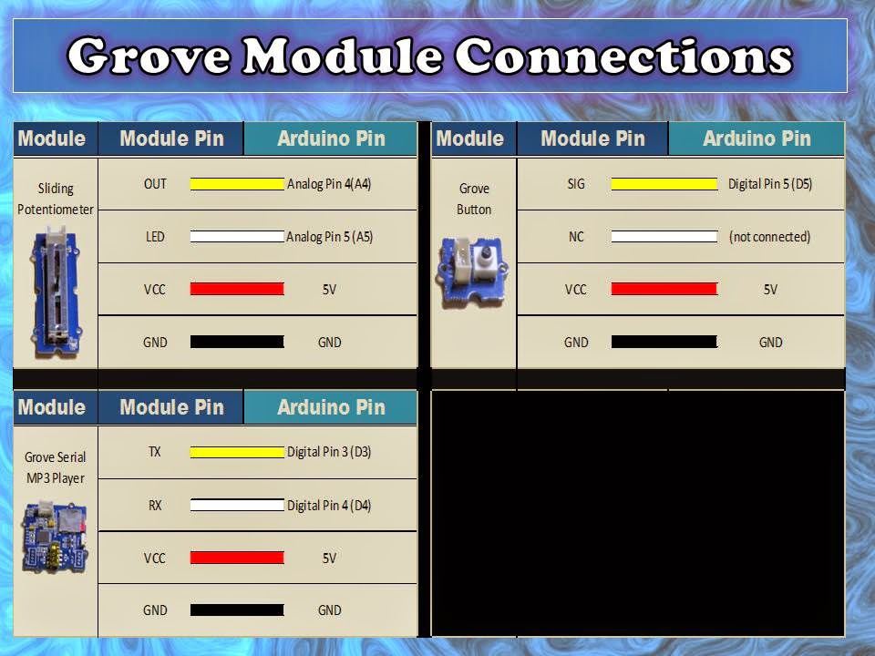
Grove Connections

Grove Connections (without base shield)
Arduino Sketch
1 |
|
Arduino Code Discussion
You can see from the Arduino code above, that it uses the ADCTouch library. This library was chosen over the Capacitive Sensing Library to eliminate the need for a high value resistor which are commonly found in Capacitive Sensing projects).To increase the speed of the Analog readings, I utilised one of the "Advanced Arduino ADC" techniques described by Guy van den Berg on this Microsmart website.
The readings are increased by modifying the Arduino's ADC clock speed from 125kHz to 250 kHz. I did notice an overall better response time with this modification. However, the Grove Serial MP3 player is limited by it's inability to play more than one song or sound at a time. This means that if you hit another drum pad while the current sound is playing, it will stop playing the current sound, and then play the selected sound. The speed at which it can perform this task was quite impressive. In fact it was much better than I thought it would be. But if you are looking for polyphonic playability, you will be dissapointed.
This Serial MP3 module makes use of a high quality MP3 audio chip known as the "WT5001". Therefore, you should be able to get some additional features and functionality from this document. Plus you may find some extra useful info from the Seeedstudio wiki. I have re-used some code from the Arduino Boombox tutorial... you will find extra Grove Serial MP3 functions on that page.
I will warn you... the Grove Serial MP3 player can play WAV files, however for some reason it would not play many of the sound files in this format. Once the sounds were converted to the MP3 format, I did not look back. So if you decide to take on this project, make sure your sound files are in MP3 format, you'll have a much better outcome.
I decided to introduce a random sound selection for each drum pad to extend the novelty of this instrument, which meant that I had to come up with a fancy way to illuminate the LEDs. I demonstrated some of my other LED sequences on my instagram account. I sometimes use instagram to show my work in progress.
Have a look at the video below to see this project in action, and putting the Grove Serial MP3 player through it's paces.
The Video

Whenever I create a new project, I like to improve my Arduino knowledge. Sometimes it takes me into some rather complicated topics. There is a lot I do not know about Arduino, but I am enjoying the journey. I hope you are too !! Please Google plus one this post if it helped you in any way. These tutorials are free, which means I survive on feedback and plus ones... all you have to do is just scroll a little bit more and click that button :)
Visit my ArduinoBasics Google + page.
Follow me on Twitter by looking for ScottC @ArduinoBasics.
I can also be found on Pinterest and Instagram.
Have a look at my videos on my YouTube channel.

However, if you do not have a google profile...
Feel free to share this page with your friends in any way you see fit.