Posts with «avr» label

Learn Microchip AVR Programming with “AVR Workshop A Hands-On Introduction with 60 Projects”

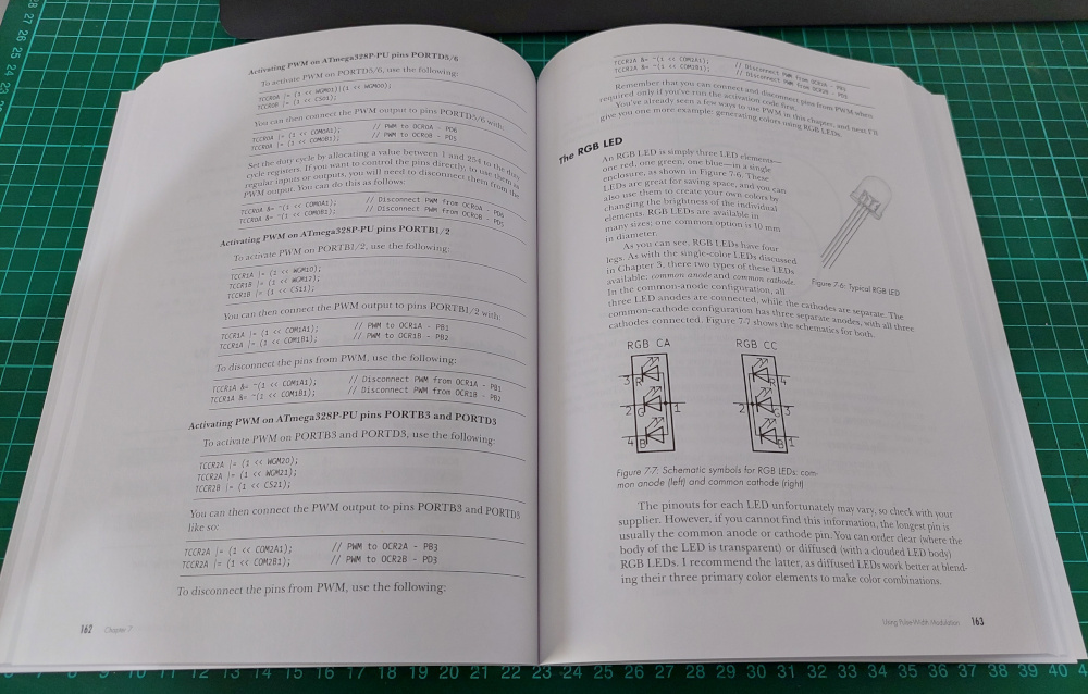
After many years working with and teaching others about the Arduino development platform, it became apparent that there needed to be a useful guide to get people started in the world of AVR microcontrollers – used in Arduino and other development environments. The great people at No Starch Press agreed and we are now proud to have published “AVR Workshop – A Hands-On Introduction with 60 Projects“.

AVR Workshop is written for several groups of people:

  • Those of you who have used an Arduino but now want to learn how to harness the underlying AVR microcontrollers without the layer of Arduino abstraction.
  • Anyone interested in electronics and wanting to start with using microcontrollers.
  • Students who are going to learn how to use AVR microcontrollers in their coursework.
  • People tasked with making devices based around 8-bit AVR microcontrollers and don’t know where to start
  • AVR users who would like a neat reference on using popular devices with their microcontrollers and don’t have all day to scour the Internet for tested, quality resources.
  • You. Yes, you. Learning is for a lifetime, so why not get started with the world of electronics and microcontrollers? Or give a copy to someone who enjoys learning about technology?

Anyone can use this book. You don’t need any previous experience in electronics, programming, or making things. AVR Workshop will take you step-by-step from the beginning including installation of the required software, explain electronics when required, teach you the required coding and walk you through examples including sixty projects enabling you to harness popular 8-bit Microchip AVR microcontrollers.

Once you’ve worked through the book – you will have the knowledge, experience and confidence to branch out on your own and build complex projects, work with other Microchip AVR microcontrollers – and find success in this fascinating field. You will also have a useful reference tool that you can refer to when making your own devices.

Unlike other books or resources found online, I don’t hide any details from you in order to simplify things. Important functions aren’t hidden away in software libraries – instead you’ll learn how to control the microcontroller down to the register level to control all sorts of useful devices. Instead of relying on others – you’ll learn how to write your own libraries, so you can make your own parts and devices easier to work with.

You don’t need to spend a fortune, in fact I’ve written AVR Workshop to be as economical as possible for you, the reader. The required software is small, free to download and can operate on Linux, MacOS or Windows using machines that date back almost ten years. You don’t need any cloud-based tools or the latest i7 or M2-based computer… almost any will do.

AVR Workshop is printed using a convenient lie-flat technology, so you can have the book open to your side and not worry about the pages flapping about and losing your position while working on your projects. All the required code is included in the book, however you can also download them along with a list of parts and supplier information from the book’s website.

The Microchip AVR series of 8-bit microcontrollers are, in my opinion, an inexpensive and most approachable way of learning about electronics and microcontrollers – and open up a whole new world of creativity or even the pathway to a career in technology. A copy of AVR Workshop is the best guide to start anyone in this world.

To learn more about AVR Workshop, you can review the table of contents, download a sample chapter, code and parts list and order copies for yourself and others from the No Starch Press online store. Orders from No Starch Press also include a free electronic copy so you can get started immediately.

You can also purchase copies from amazonkindle, or your preferred bookseller. Readers in Australia can order directly from the Tronixlabs store.

And whatever you do, have fun and make something!

Tronixstuff 17 Oct 01:48
avr  microchip  

Blinking an Arduino LED, in Julia

The Julia programming language is a horrible fit for a no-frills microcontroller like the ATMega328p that lies within the classic Arduino, but that didn’t stop [Sukera] from trying, and succeeding.

All of the features that make Julia a cool programming language for your big computer make it an awful choice for the Arduino. It’s designed for interactivity, is dynamically typed, and leans heavily on its garbage collection; each of these features alone would tax the Mega to the breaking point. But in its favor, it is a compiled language that is based on LLVM, and LLVM has an AVR backend for C. Should just be a simple matter of stubbing out some of the overhead, recompiling LLVM to add an AVR target for Julia, and then fixing up all the other loose ends, right?

Well, it turns out it almost was. Leaning heavily on the flexibility of LLVM, [Sukera] manages to turn off all the language features that aren’t needed, and after some small hurdles like the usual problems with volatile and atomic variables, manages to blink an LED slowly. Huzzah. We love [Sukera’s] wry “Now THAT is what I call two days well spent!” after it’s all done, but seriously, this is the first time we’ve every seen even super-rudimentary Julia code running on an 8-bit microcontroller, so there are definitely some kudos due here.

By the time that Julia is wedged into the AVR, a lot of what makes it appealing on the big computers is missing on the micro, so we don’t really see people picking it over straight C, which has a much more developed ecosystem. But still, it’s great to see what it takes to get a language designed around a runtime and garbage collection up and running on our favorite mini micro.

Thanks [Joel] for the tip!

This DIY UPDI Programmer is Nice and Cheap

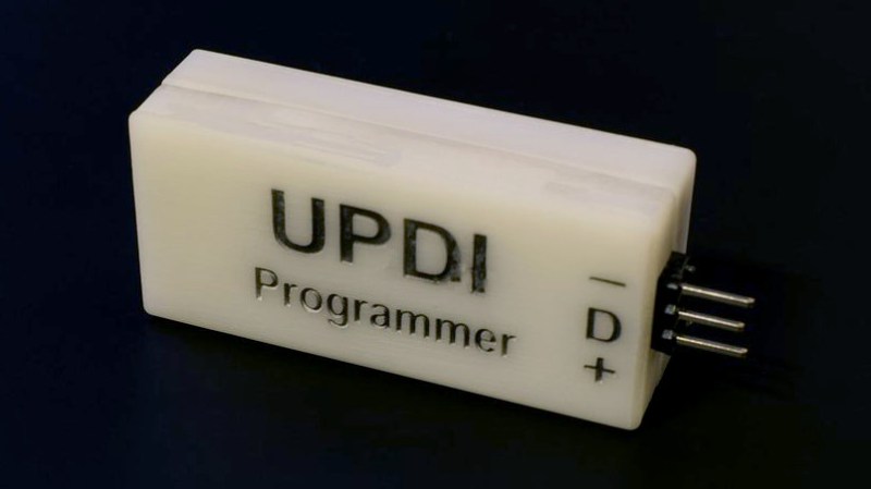
[Daumemo] likes experimenting with DIY electronics, and like many people, eventually ran across an AVR microcontroller with a Unified Program and Debug Interface (UPDI). One option is of course to purchase an UPDI programmer, but an even better solution was to make a DIY USB version from nice, cheap parts.

Programming an Attiny404 over the UPDI interface.

UPDI is an interface for external programming and on-chip debugging of microcontrollers, and [Daumemo]’s solution is based on the jtag2updi project. It combines an Arduino Nano (in this case, a clone) with a single resistor, a single capacitor, and a six pin angled header (with a cleverly bent pin) to enable programming UPDI devices over a USB connection. [Daumemo] is happy to report that the device works just fine in both Microchip Studio with AVRDUDE, or PlatformIO.

Is an Arduino Nano a bit overpowered in this role? Maybe, but the price is certainly right. There’s no need for a custom PCB either, since everything can be soldered direct to the Nano board. A matching 3D printed enclosure is about all that’s needed to make a robust and reliable DIY USB UPDI programmer out of a handful of parts, and that sounds good to us.

On the other hand, if you do find yourself making custom PCBs, you may be interested in another of [Daumemo]’s DIY projects: a printable structure to turn a rotary tool into a PCB drill press.

AVR Reverse Engineering Hack Chat

Join us on Wednesday, April 21 at noon Pacific for the AVR Reverse Engineering Hack Chat with Uri Shaked!

We’ve all become familiar with the Arduino ecosystem by now, to the point where it’s almost trivially easy to whip up a quick project that implements almost every aspect of its functionality strictly in code. It’s incredibly useful, but we tend to lose sight of the fact that our Arduino sketches represent a virtual world where the IDE and a vast selection of libraries abstract away a lot of the complexity of what’s going on inside the AVR microcontroller.

While it’s certainly handy to have an environment that lets you stand up a system in a matter of minutes, it’s hardly the end of the story. There’s a lot to be gained by tapping into the power of assembly programming on the AVR, and learning how to read the datasheet and really run the thing. That was the focus of Uri Shaked’s recent well-received HackadayU course on AVR internals, and it’ll form the basis of this Hack Chat. Then again, since Uri is also leading a Raspberry Pi Pico and RP2040 course on HackadayU in a couple of weeks, we may end up talking about that too. Or we may end up chatting about something else entirely! It’s really hard to where this Hack Chat will go, given Uri’s breadth of interests and expertise, but we’re pretty sure of one thing: it won’t be boring. Make sure you log in and join the chat — where it goes is largely up to you.

Our Hack Chats are live community events in the Hackaday.io Hack Chat group messaging. This week we’ll be sitting down on Wednesday, April 21 at 12:00 PM Pacific time. If time zones have you tied up, we have a handy time zone converter.

Click that speech bubble to the right, and you’ll be taken directly to the Hack Chat group on Hackaday.io. You don’t have to wait until Wednesday; join whenever you want and you can see what the community is talking about.

Want to Learn Ethernet? Write Your Own Darn AVR Bootloader!

There’s a school of thought that says that to fully understand something, you need to build it yourself. OK, we’re not sure it’s really a school of thought, but that describes a heck of a lot of projects around these parts.

[Tim] aka [mitxela] wrote kiloboot partly because he wanted an Ethernet-capable Trivial File Transfer Protocol (TFTP) bootloader for an ATMega-powered project, and partly because he wanted to understand the Internet. See, if you’re writing a bootloader, you’ve got a limited amount of space and no device drivers or libraries of any kind to fall back on, so you’re going to learn your topic of choice the hard way.

[Tim]’s writeup of the odyssey of cramming so much into 1,000 bytes of code is fantastic. While explaining the Internet takes significantly more space than the Ethernet-capable bootloader itself, we’d wager that you’ll enjoy the compressed overview of UDP, IP, TFTP, and AVR bootloader wizardry as much as we did. And yes, at the end of the day, you’ve also got an Internet-flashable Arduino, which is just what the doctor ordered if you’re building a simple wired IoT device and you get tired of running down to the basement to upload new firmware.

Oh, and in case you hadn’t noticed, cramming an Ethernet bootloader into 1 kB is amazing.

Speaking of bootloaders, if you’re building an I2C slave device out of an ATtiny85¸ you’ll want to check out this bootloader that runs on the tiny chip.

Simulate PIC and Arduino/AVR Designs with no Cloud

I’ve always appreciated simulation tools. Sure, there’s no substitute for actually building a circuit but it sure is handy if you can fix a lot of easy problems before you start soldering and making PCBs. I’ve done quite a few posts on LTSpice and I’m also a big fan of the Falstad simulator in the browser. However, both of those don’t do a lot for you if a microcontroller is a major part of your design. I recently found an open source project called Simulide that has a few issues but does a credible job of mixed simulation. It allows you to simulate analog circuits, LCDs, stepper and servo motors and can include programmable PIC or AVR (including Arduino) processors in your simulation.

The software is available for Windows or Linux and the AVR/Arduino emulation is built in. For the PIC on Linux, you need an external software simulator that you can easily install. This is provided with the Windows version. You can see one of several videos available about an older release of the tool below. There is also a window that can compile your Arduino code and even debug it, although that almost always crashed for me after a few minutes of working. As you can see in the image above, though, it is capable of running some pretty serious Arduino code as long as you aren’t debugging.

Looks and sounds exciting, right? It is, but be sure to save often. Under Linux, it seems to crash pretty frequently even if you aren’t debugging. It also suffers from other minor issues like sometimes forgetting how to move components. Saving, closing the application, and reopening it seems to fix that. Plus, we assume they will squash bugs as they are reported. One of my major hangs was solved by removing the default (old) Arduino IDE and making sure the most recent was on the path. But the crashing was frequent and seemed more or less random. It seemed that I most often had crashes on Linux with occasional freezes but on Windows it would freeze but not totally crash.

Basic Operation

The basic operation is pretty much what you’d expect. The window is broadly divided into three panes. The leftmost pane shows, by default, a palette of components. You can use the vertical tab strip on the left to also pick a memory viewer, a property inspector, or a file explorer.

The central pane is where you can draw your circuit and it looks like a yellow piece of engineering paper with a grid. Along the top are file buttons that do things like save and load files.

You’ll see a similar row of buttons above the rightmost pane. This is a code editor and debugging window that can interface with the Arduino IDE. It looks like it can also interface with GCBasic for the PIC, although I didn’t try that.

You drag components from the left onto the circuit. Wiring isn’t a distinct operation. You just let the mouse float over the connection until the cursor makes a cross. Click and then drag to the connection point and click again. Sometimes the program forgets to make the cross cursor and then I’ve had to save and restart.

Most of the components are just what you think they are. There are some fun ones including a keypad, an LED matrix, text and graphic LCDs, and even stepper and servo motors. You’ll also find several logic functions, 7400-series ICs, and there are annotation tools like text and boxes at the very bottom. You can right click on a category and hide components you never want to see.

At the top, you can add a voltmeter, an ammeter, or an oscilloscope to your circuit. The oscilloscope isn’t that useful because it is small. What you really want to do is use a probe. This just shows the voltage at some point but you can right click on it and add the probe to the plotter which appears at the bottom of the screen. This is a much more useful scope option.

There are a few quirks with the components. The voltage source has a push button that defaults to off. You have to remember to turn it on or things won’t work well. The potentiometers were particularly frustrating. The videos of older versions show a nice little potentiometer knob and that appears on my Windows laptop, too. On Linux the potentiometer (and the oscilloscope controls) look like a little tiny joystick and it is very difficult to set a value. It is easier to right click and select properties and adjust the value there. Just note that the value won’t change until you leave the field.

Microcontroller Features

If that’s all there was to it, you’d be better off using any of a number of simulators that we’ve talked about before. But the big draw here is being able to plop a microcontroller down in your circuit. The system provides PIC and AVR CPUs that are supported by the simulator code it uses. There’s also four variants of Arduinos: the Uno, Nano, Duemilanove, and the Leonardo.

You can use the built-in Arduino IDE — just make sure you have the real Arduino software on your path and it is a recent version. Also, unlike the real IDE, it appears you must save your file before a download or debug will notice the changes. In other words, if you make a change and download, you’ll compile the code before the change if you didn’t save the file first. You don’t have to use the built-in IDE. You can simply right click on the processor and upload a hex file. Recent Arduino IDEs have an option to export a hex file, and that works with no problem.

When you have a CPU in your design, you can right click it and open a serial monitor port which shows virtual serial output at the bottom of the screen and lets you provide input.

The debugging mode is simple but works until it crashes. Even without debugging, there is an option to the left of the screen to watch memory locations and registers inside the CPU.

Overall, the Arduino simulation seemed to work quite well. Connecting to the Uno pins was a little challenging at certain scales and I accidentally wired to the wrong pin on more than one occasion. One thing I found odd is that you don’t need to wire the voltage to the Arduino. It is powered on even if you don’t connect it.

Besides the crashing, the other issue I had was with the simulation speed which was rather slow. There’s a meter at the top of the screen that shows how slow the simulation is compared to real-time and mine was very low (10% or so) most of the time. There is a help topic explaining that this depends if you have certain circuit elements and ways to improve the run time, but it wasn’t bad enough that I bothered to explore it.

My first thought was that it would be difficult to handle a circuit with multiple CPUs in it since the debugging and serial monitors are all set up for a single CPU. However, as the video below shows, you can run multiple instances of the program and connect them via a serial port connection. The only issue would be if you had a circuit where both CPUs were interfacing with interrelated circuitry (for example, an op amp summing two signals, one from each CPU).

A Simple Example

As an experiment, I created a simple circuit that uses an Uno. It generates two PWM signals, integrates them with an RC circuit and then either drives a load or drives a load through a bipolar emitter follower. A pot lets you set the PWM percentages which are compliments of each other (that is, when one is at 10% the other is at 90%). Here’s the circuit:

Along with the very simple code:

int v;

const int potpin=0;
const int led0=5;
const int led1=6;

void setup() {
Serial.begin(9600);
Serial.println("Here we go!");
}

void loop() {
int v=analogRead(potpin)/4;
Serial.println(v);
analogWrite(led0,v);
analogWrite(led1,255-v);
delay(250);
}

Note that if the PWM output driving the transistor drops below 0.7V or so, the transistor will shut off. I deliberately didn’t design around that because I wanted to see how the simulator would react. It correctly models this behavior.

There’s really no point to this other than I wanted something that would work out the analog circuit simulation as well as the Arduino. You can download all the files from GitHub, including the hex file if you want to skip the compile step.

If you use the built-in IDE on the right side of the screen, then things are very simple. You just download your code. If you build your own hex file, just right click on the Arduino and you’ll find an option to load a hex file. It appears to remember the hex file, so if you run a simulation again later, you don’t have to repeat that step unless you moved the hex file.

However, the IDE doesn’t remember settings for the plotter, the voltage switches, or the serial terminal. You’ll especially want to be sure the 5V power switch above the transistor is on or that part of the circuit won’t operate correctly. You can right click on the Arduino to open the serial monitor and right click on the probes to bring back the plotter pane.

The red power switch at the top of the window will start your simulation. The screenshots above show close-ups of the plot pane and serial monitor.

Lessons Learned

This could be a really great tool if it would not crash so much. In all fairness, that could have something to do with my PC, but I don’t think that fully accounts for all of them. However, the software is still in pretty early development, so perhaps it will get better. There are a lot of fit and finish problems, too. For example, on my large monitor, many of the fonts were too large for their containers, which isn’t all that unusual.

The user interface seemed a little clunky, especially when you had to manipulate potentiometers and switches. Also, remember you can’t right-click on the controls but must click on the underlying component. In other words, the pot looks like a knob on top of a resistor. Right clicks need to go on the resistor part, not the knob. I also was a little put off that you can’t enter multiplier suffixes directly in component values. That is, you can’t enter a resistor value as 1K. You can enter 1000 or you can enter 1 and then change the units in a separate field to Kohms. But that’s not a big deal. You can get used to all of that if it would quit crashing.

I really wanted the debugging feature to work. While you can debug directly with simuavr or other tools, you can’t easily simulate all your I/O devices like you can with this tool. I’m hoping that becomes more robust in the future. Under Linux it would work for a bit and crash. On Windows, I never got it to work.

As I always say, though, simulation is great, but the real world often leads to surprises that don’t show up in simulation. Still, a simulation can help you clear up a host of problems before you commit to heating up the soldering iron or pulling out the breadboard. Simuide has the potential to be a great tool for simulating the kind of designs we see most on Hackaday.

If you want to explore other simulation options, we’ve talked a lot about LTSpice, including our Circuit VR series. There’s also the excellent browser-based Falstad simulator.
Ask Hackaday Answered: The Tale of the Top-Octave Generator

We got a question from [DC Darsen], who apparently has a broken electronic organ from the mid-70s that needs a new top-octave generator. A top-octave generator is essentially an IC with twelve or thirteen logic counters or dividers on-board that produces an octave’s worth of notes for the cheesy organ in question, and then a string of divide-by-two logic counters divide these down to cover the rest of the keyboard. With the sound board making every pitch all the time, the keyboard is just a simple set of switches that let the sound through or not. Easy-peasy, as long as you have a working TOG.

I bravely, and/or naïvely, said that I could whip one up on an AVR-based Arduino, tried, and failed. The timing requirements were just too tight for the obvious approach, so I turned it over to the Hackaday community because I had this nagging feeling that surely someone could rise to the challenge.

The community delivered! Or, particularly, [Ag Prismatic]. With a clever approach to the problem, some assembly language programming, and an optional Arduino crystalectomy, [AP]’s solution is rock-solid and glitch-free, and you could build one right now if you wanted to. We expect a proliferation of cheesy synth sounds will result. This is some tight code. Hat tip!

Squeezing Cycles Out of a Microcontroller

Let’s take a look at [AP]’s code. The approach that [AP] used is tremendously useful whenever you have a microcontroller that has to do many things at once, on a rigid schedule, and there’s not enough CPU time between the smallest time increments to do much. Maybe you’d like to control twelve servo motors with no glitching? Or drive many LEDs with binary code modulation instead of primitive pulse-width modulation? Then you’re going to want to read on.

There are two additional tricks that [AP] uses: one to fake cycles with a non-integer number of counts, and one to make the AVR’s ISR timing absolutely jitter-free. Finally, [Ag] ended up writing everything in AVR assembly language to make the timing work out, but was nice enough to also include a C listing. So if you’d like to get your feet wet with assembly, this is a good start.

In short, if you’re doing anything with hard timing requirements on limited microcontroller resources, especially an AVR, read on!

Taking Time to Think

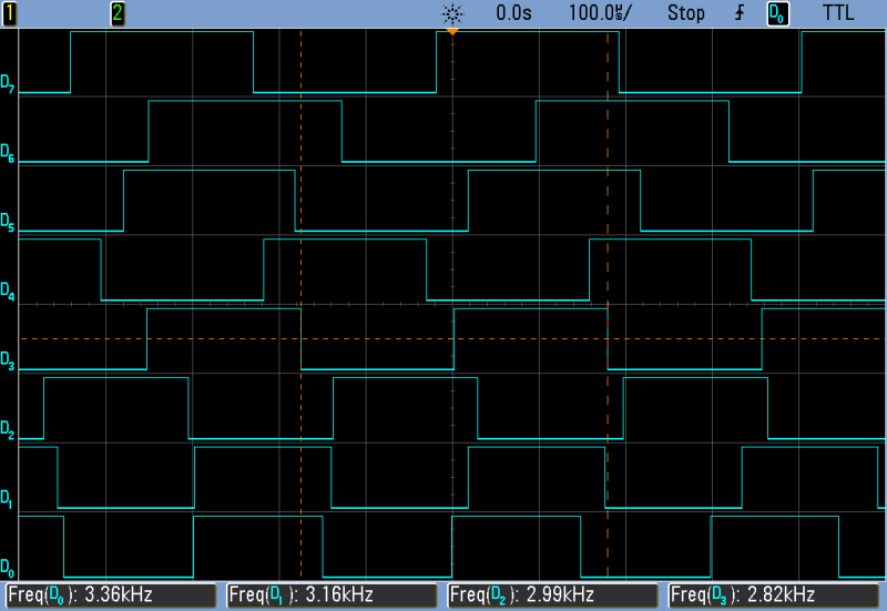
The goal of the top-octave generator is to take an input clock and divide it down into twelve simultaneous sub-clocks that all run independently of each other. Just to be clear, this means updating between zero and twelve GPIO pins at a frequency of 1 MHz or so — updating every twenty clock cycles at the AVR’s maximum CPU speed. If you thought you could loop through twelve counters and decide which pins to flip in twenty cycles, you’d be mistaken.

But recognizing the problem is the first step to solving it. Although the tightest schedule might require flipping one pin exactly twenty clocks after flipping another, most of the time there are more cycles between pin updates — hundreds up to a few thousand. So the solution is to recognize when there is time to think, and use this time to pre-calculate a buffer full of next states.

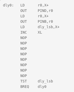
[Ag]’s solution uses a few different loops that run exactly 20, 40, and 60 cycles each — the longer versions being just the 20-cycle one padded out with NOPs. These loops run inside an interrupt-service routine (ISR). When there are 80 or more cycles of thinking time until the next scheduled pin change, control is returned to the main loop and the next interrupt is set to re-enter the tight loops at the next necessary update time.

All the fast loop has to do is read two bytes, write them out to the GPIO pins, increment the pointer to the next row of data, and figure out if it needs to stall for 20 or 40 additional cycles, or set the ISR timer for longer delays and return to calculations. And this it can do in just twelve of the twenty cycles! Slick.

Buffers

Taking a step back from the particulars of the top-octave generator, this is a classic problem and a classic solution. It’s worth your time to internalize it, because you’ll run into this situation any time you have real-time constraints. The problem is that on average there’s more than enough time to complete the calculations, but that in the worst cases it’s impossible. So you split the problem in two parts: one that runs as fast as possible, and one that does the calculations that the fast section will need. And connecting together fast and slow processes is exactly why computer science gave us the buffer.

In [AP]’s code, this buffer is a table where each entry has two bytes for the state of the twelve GPIO pins, and one byte to store the number of clock cycles to delay until the next update. One other byte is left empty, yielding 64 entries or 256 bytes for the whole table. Why 256 bytes? Because the AVR has an 8-bit unsigned integer, wrapping around from the end of the table back to the beginning is automatic, saving a few cycles of wasteful if statements.

But even with this fast/slow division of labor, there is not much time left over for doing the pre-calculation. Sounding the highest C on a piano keyboard (4186 Hz) with a 20 MHz CPU clock requires toggling a GPIO pin every 2,390 cycles, so that’s the most time that the CPU will ever see. When the virtual oscillators are out of phase, this can be a lot shorter. By running the AVR at its full 20 MHz, and coding everything in assembly, [AP] can run the calculations fast enough to support twelve oscillators. At 16 MHz, there’s only time for ten, so every small optimization counts.

Some Optimization Required

Perhaps one of the cleverest optimizations that [AP] made is the one that makes this possible at all. The original top-octave chips divide down a 2 MHz square wave by a set of carefully chosen integer divisors. Running the AVR equivalent at 2 MHz resolution would mean just ten clocks per update and [AP]’s fast routine needed twelve, so the update rate would have to be halved. But that means that some odd divisors on the original IC would end up non-integral in the AVR code. For example, the highest C is reproduced in silicon as 2 MHz / 239, so to pull this off at 1 MHz requires counting up to 119.5 on an integer CPU. How to cope?

You could imagine counting to 119 half of the time, and 120 the other. Nobody will notice the tiny difference in duty cycle, and the pitch will still be spot on. The C programmer in me would want to code something like this:

uint8_t counter[12] = { 0, ... };
uint8_t counter_top[12] = { 119, ... };
uint8_t is_counter_fractional[12] = { 1, 0, ... };
uint8_t is_low_this_time[12] = { 0, ... };

// and then loop
for ( i=0 ; i<12; ++i){
  if ( counter[i] == 0 ){
    if ( is_counter_fractional[i] ){
      if ( is_low_this_time[i] ){
        counter[i] = counter_top[i];
    is_low_this_time = 0;
      else {
        counter[i] = counter_top[i] + 1;
    is_low_this_time = 1;
      }
    }
  }
}

That will work, but the ifs costs evaluation time. Instead, [AP] did the equivalent of this:

uint8_t counter[12] = { 0, ... };
uint8_t counter_top[12] = { 119, ... };
uint8_t phase[12] = { 1, 0, ... };

for ( i=0 ; i<12; ++i){
  if ( counter[i] == 0 ){
    counter[i] = counter_top[i] + phase[i];
    counter_top[i] = counter[i];
    phase[i] = -phase[i];
  }
}

What’s particularly clever about this construction is that it doesn’t need to distinguish between the integer and non-integer delays in code. Alternately adding and subtracting one from the non-integer values gets us around the “half” problem, while setting the phase variable to 0 means that the integer-valued divisors run unmodified, with no ifs.

The final optimization shows just how far [AP] went to make this AVR top-octave generator work like the real IC. When setting the timer to re-enter the fast loop in the ISR, there’s the possibility for one cycle’s worth of jitter. Because AVR instructions run in either one or two clock cycles, it’s possible that a two-cycle instruction could be running when the ISR timer comes due. Depending on luck, then, the interrupt will run four or five clocks later: see the section “Interrupt Response Time” in the AVR data sheet for details.

In a prologue to the ISR, [AP]’s code double-checks the hardware timer to see if it has entered on a one-cycle instruction, and adds in an extra NOP to compensate. This makes the resulting oscillator nearly jitter free, pushing out a possible source of 50 ns (one cycle at 20 MHz) slop. I don’t think you’d be able to hear this jitter, but the result surely looks pretty on the oscilloscope, and this might be a useful trick to know if you’re ever doing ultra-precise timing with ISRs.

The Proof of the Pudding

Naturally, I had to test out this code on real hardware. The first step was to pull a random Arduino-clone out of the closet and flash it in. Because “Arduinos” run at 16 MHz with the stock crystal, the result is that a nominal 440 Hz concert A plays more like a slightly sharp F, a musical third down. It sounds fine on its own, but you won’t be able to play along with any other instruments that are tuned to 440 Hz.

[AP]’s preferred solution is to run the AVR chip at 20 MHz. Since the hardware requirements are very modest, you could use a $0.50 ATTiny816 coupled with a 20 MHz crystal and you’d have a top-octave generator for literal pocket change — certainly cheaper than buying even an Arduino clone. I tested it out with an ATMega48P and a 20 MHz crystal on a breadboard because it’s what I had. Or you could perform crystalectomy on your Arduino to get it running at full speed.

We went back and forth via e-mail about all the other (firmware) options. [AP] had tried them all. You could trim the ISR down to 16 cycles and run at 16 MHz, but then there’s only enough CPU time in the main loop to support ten notes, two shy of a full octave. You could try other update rates than 1 MHz, but the divisors end up being pretty wonky. To quote [AP] from our e-mail discussion on the topic:

“After playing with the divider values from the original top octave generator IC and trying different base frequencies, it appears that the 2 MHz update rate is a “sweet spot” for getting reasonable integer divisors with < +/-2 cents of error. The original designers of the chip must have done the same calculations.”

To make a full organ out of this setup, you’ll also need twelve binary counter chips to divide down each note to fill up the lower registers of the keyboard, but these are easy to design with and cost only a few tens of cents apiece. All in all, thanks to [AP]’s extremely clever coding, you can build a fully-polyphonic noisemaker that spits out 96 simultaneous pitches, all in tune, for under $10. That’s pretty amazing.

And of course, I’ve already built a small device based on this code, but that’s a topic for another post. To be continued.

Debugging an Arduino with an Arduino

As every Hackaday reader knows, and tells us at every opportunity in the comments, adding an Arduino to your project instantly makes it twice as cool. But what if, in the course of adding an Arduino to your project, you run into a problem and need to debug the code? What if you could use a second Arduino to debug the first? That would bring your project up to two Arduinos, instantly making it four times as awesome as before you started! Who could say no to such exponential gains?

Debugging an ATTiny85

Not [Wayne Holder], that’s for sure. He writes in to let us know about a project he’s been working on for a while that allows you to debug the execution of code on an Arduino with a second Arduino. In fact, the target chip could even be another AVR series microcontroller such as a the ATTiny85. With his software you can single-step through the code, view and modify values in memory, set breakpoints, and even disassemble the code. Not everything is working fully yet, but what he has so far is very impressive.

The trick is exploiting a feature known as “debugWIRE” that’s included in many AVR microcontrollers. Unfortunately documentation on this feature is hard to come by, but with some work [Wayne] has managed to figure out how most of it works and create an Arduino Sketch that lets the user interact with the target chip using a simple menu system over the serial monitor, similar to the Bus Pirate.

[Wayne] goes into plenty of detail on his site and in the video included after the break, showing many of the functions he’s got working so far in his software against an ATTiny85. If you spend a lot of time working on AVR projects, this looks like something you might want to keep installed on an Arduino in your tool bag for the future.

Debugging microcontroller projects can be a huge time saver when your code starts running on real hardware, but often takes some hacking to get working.

DIY Tiny Single-PCB Synthesizer

[Jan Ostman] has been pushing the limits of sound synthesis on the lowly AVR ATMega microcontrollers, and his latest two project is so cute that we just had to write it up. The miniTS shares the same basic sound-generation firmware with his previous TinyTS, which we’ve covered here before, but adds a lot more keys, an OLED, and MIDI, while taking away some of the knobs.

Both feature keyboards that are just copper pads placed over a ground plane, and the code does simple capacitive-sensing to figure out if they’re being touched or not. The point here is that you could pick up a PCB from [Jan] on the cheap, and experiment around with the code. Or you could just take the code and make a less refined version for yourself with a cheapo Arduino and some copper plates.

Either way, we like the combination of minimal materials and maximum tweakability, and think it’s cool that [Jan] shares the code, if not also the PCB designs. Anyone with PCB layout practice could get a clone worked up in an afternoon, although it’s going to be cheaper to get these made in bulk, and you’re probably better off just buying one from [Jan].


Filed under: musical hacks

[SOLVED] Arduino ATTiny85 does not blink LED. Programmed with Arduino nano

Hi!


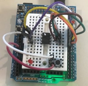
I have an ATTiny85 and I want to start with the blink LED sketch but it does not work. Attached is the wiring:

I followed these instructions: http://forums.4fips.com/viewtopic.php?f=3&t=1080 for wiring, burn both bootloader and LED blink sketch with an Arduino nano as programmer (excepting I'm using 1.8.1 nightly Arduino IDE), and everything looks like going fine:


read more

Let's Make Robots 18 Feb 10:04
arduino  attiny85  avr  nano