Project Description
In this project, your heart will control a mesmerising LED sequence on a
5 metre Neopixel LED strip with a ws2812B chipset. Every heart beat will trigger a LED animation that will keep you captivated and attached to your Arduino for ages. The good thing about this project is that it is relatively easy to set up, and requires no soldering. The hardest part is downloading and installing the FastLED library into the Arduino IDE, but that in itself is not too difficult. The inspiration and idea behind this project came from
Ali Murtaza, who wanted to know how to get an LED strip to pulse to his heart beat.
Have a look at the video below to see this project in action.
The Video
Parts Required:
Power Requirements
Before you start any LED strip project, the first thing you will need to think about is POWER. According to the Adafruit website, each individual NeoPixel LED can draw up to 60 milliamps at maximum brightness - white. Therefore the amount of current required for the entire strip will be way more than your Arduino can handle. If you try to power this LED strip directly from your Arduino, you run the risk of damaging not only your Arduino, but your USB port as well. The Arduino will be used to control the LED strip, but the LED strip will need to be powered by a separate power supply. The power supply you choose to use is important. It must provide the correct voltage, and must able to supply sufficient current.
Operating Voltage (5V)
The operating voltage of the NeoPixel strip is 5 volts DC. Excessive voltage will damage/destroy your NeoPixels.
Current requirements (9.0 Amps)
OpenLab recommend the use of a 5V 10A power supply. Having more Amps is OK, providing the output voltage is 5V DC. The LEDs will only draw as much current as they need. To calculate the amount of current this 5m strip can draw with all LEDs turned on at full brightness - white:
30 NeoPixel LEDs x
60mA x
5m =
9000mA =
9.0 Amps for a 5 metre strip. Therefore a 5V 10A power supply would be able to handle the maximum current (9.0 Amps) demanded by a 5m NeoPixel strip containing a total of 150 LEDs.
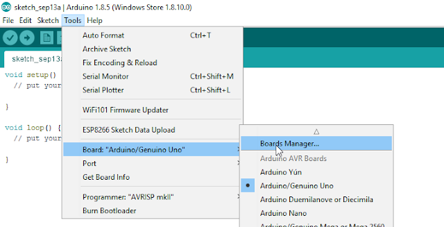
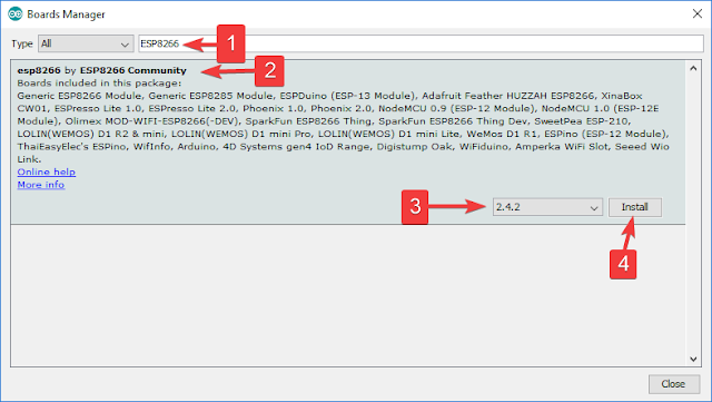
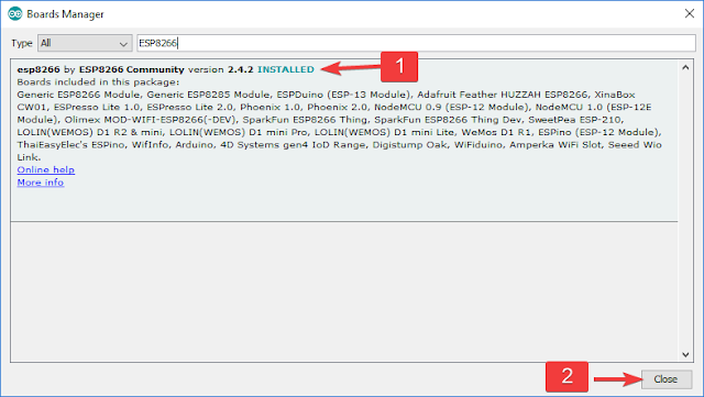
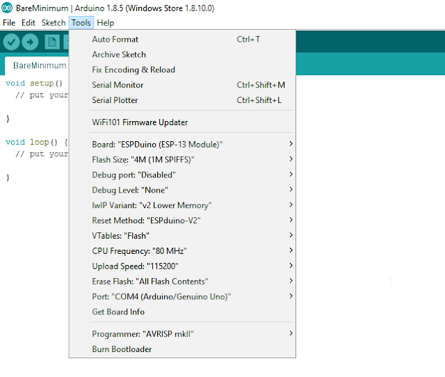
Arduino Libraries and IDE
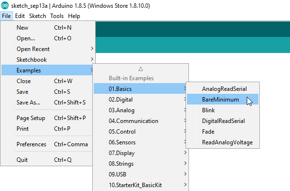
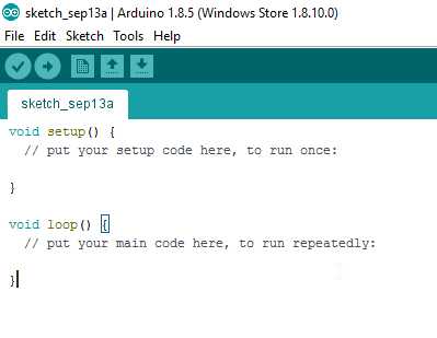
Before you start to hook up any components, upload the following sketch to the Arduino microcontroller. I am assuming that you already have the
Arduino IDE installed on your computer. If not, the IDE can be downloaded from
here.
The
FastLED library is useful for simplifying the code for programming the NeoPixels. The latest "FastLED library" can be downloaded from
here. I used FastLED library version
3.0.3 in this project.
If you have a different LED strip or your NeoPixels have a different chipset, make sure to change the relevant lines of code to accomodate your hardware. I would suggest you try out a few of the
FastLED library examples before using the code below, so that you become more familiar with the library, and will be better equipped to make the necessary changes. If you have a 5 metre length of the NeoPixel 30 LED/m strip with the ws2812B chipset, then you will not have to make any modification below.
ARDUINO CODE:
1
2
3
4
5
6
7
8
9
10
11
12
13
14
15
16
17
18
19
20
21
22
23
24
25
26
27
28
29
30
31
32
33
34
35
36
37
38
39
40
41
42
43
44
45
46
47
48
49
50
51
52
53
54
55
56
57
58
59
60
61
62
63
64
65
66
67
68
69
70
71
72
73
74
75
76
77
78
79
80
81
82
83
84
85
86
87
88
89
90
91
92
93
94
95
96
97
98
99
100
101
102
103
104
105
106
107
108
109
110
111
112
113
114
115
116
117
118
119
120
121
122
123
124
125
126
127
128
129
130
131
132
133
134
135
136
137
138
139
140 | /* ================================================================================================ Project: NeoPixel Heart Beat Display Neopixel chipset: ws2812B (30 LED/m strip) Author: Scott C Created: 8th July 2015 Arduino IDE: 1.6.4 Website: http://arduinobasics.blogspot.com/p/arduino-basics-projects-page.html Description: This sketch will display a heart beat on a 5m Neopixel LED strip. Requires a Grove Ear-clip heart rate sensor and a Neopixel strip. This project makes use of the FastLED library: http://fastled.io/ You may need to modify the code below to accomodate your specific LED strip. See the FastLED library site for more details. ================================================================================================== */ //This project needs the FastLED library - link in the description. #include "FastLED.h" //The total number of LEDs being used is 150 #define NUM_LEDS 150 // The data pin for the NeoPixel strip is connected to digital Pin 6 on the Arduino #define DATA_PIN 6 //Attach the Grove Ear-clip heart rate sensor to digital pin 2 on the Arduino. #define EAR_CLIP 2 //Initialise the LED array CRGB leds[NUM_LEDS]; //Initialise the global variables used to control the LED animation int ledNum = 0; //Keep track of the LEDs boolean beated = false; //Used to identify when the heart has beated int randomR = 0; //randomR used to randomise the fade-out of the LEDs //================================================================================================ // setup() : Is used to initialise the LED strip //================================================================================================ void setup() { FastLED.addLeds<NEOPIXEL,DATA_PIN>(leds, NUM_LEDS); //Set digital pin 2 (Ear-clip heart rate sensor) as an INPUT pinMode(EAR_CLIP, INPUT);} //================================================================================================ // loop() : Take readings from the Ear-clip sensor, and display the animation on the LED strip //================================================================================================ void loop() { //If the Ear-clip sensor moves from LOW to HIGH, call the beatTriggered method if(digitalRead(EAR_CLIP)>0){ //beatTriggered() is only called if the 'beated' variable is false. //This prevents multiple triggers from the same beat. ifbeated){ beatTriggered(); } } else { beated = false; //Change the 'beated' variable to false when the Ear-clip heart rate sensor is reading LOW. } //Fade the LEDs by 1 unit/cycle, when the heart is at 'rest' (i.e. between beats) fadeLEDs(5);} //================================================================================================ // beatTriggered() : This is the LED animation sequence when the heart beats //================================================================================================ void beatTriggered(){ //Ignite 30 LEDs with a red value between 0 to 255 for(int i = 0; i<30; i++){ //The red channel is randomised to a value between 0 to 255 leds[ledNum].r=random8(); FastLED.show(); //Call the fadeLEDs method after every 3rd LED is lit. if(ledNum%3==0){ fadeLEDs(5); } //Move to the next LED ledNum++; //Make sure to move back to the beginning if the animation falls off the end of the strip if(ledNum>(NUM_LEDS-1)){ ledNum=0; } } //Ignite 20 LEDS with a blue value between 0 to 120 for(int i = 0; i<20; i++){ //The blue channel is randomised to a value between 0 to 120 leds[ledNum].b=random8(120); FastLED.show(); //Call the fadeLEDs method after every 3rd LED is lit. if(ledNum%3==0){ fadeLEDs(5); } //Move to the next LED ledNum++; //Make sure to move back to the beginning if the animation falls off the end of the strip if(ledNum>(NUM_LEDS-1)){ ledNum=0; } } //Change the 'beated' variable to true, until the Ear-Clip sensor reads LOW. beated=true;} //================================================================================================ // fadeLEDs() : The fading effect of the LEDs when the Heart is resting (Ear-clip reads LOW) //================================================================================================ void fadeLEDs(int fadeVal){ for (int i = 0; i<NUM_LEDS; i++){ //Fade every LED by the fadeVal amount leds[i].fadeToBlackBy( fadeVal ); //Randomly re-fuel some of the LEDs that are currently lit (1% chance per cycle) //This enhances the twinkling effect. if(leds[i].r>10){ randomR = random8(100); if(randomR<1){ //Set the red channel to a value of 80 leds[i].r=80; //Increase the green channel to 20 - to add to the effect leds[i].g=20; } } } FastLED.show();} |
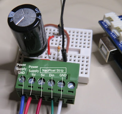
NeoPixel Strip connection
The NeoPixel strip is rolled up when you first get it. You will notice that there are wires on both sides of the strip. This allows you to chain LED strips together to make longer strips. The more LEDs you have, the more current you will need. Connect your Arduino and power supply to the left side of the strip, with the arrows pointing to the right. (i.e. the side with the "female" jst connector).
NeoPixel Strip Wires
There are 5 wires that come pre-attached to either side of the LED strip.
You don't have to use ALL FIVE wires, however you will need at least one of each colour: red, white & green.
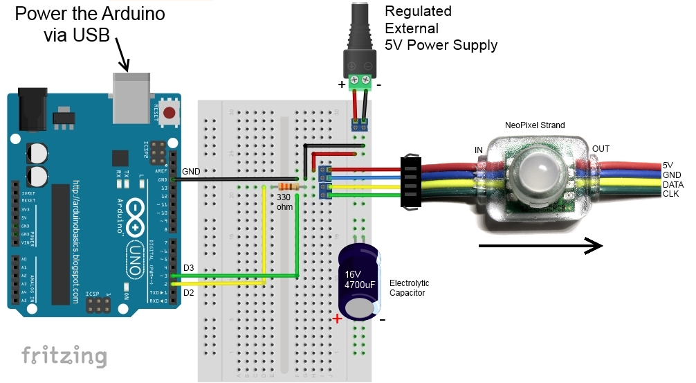
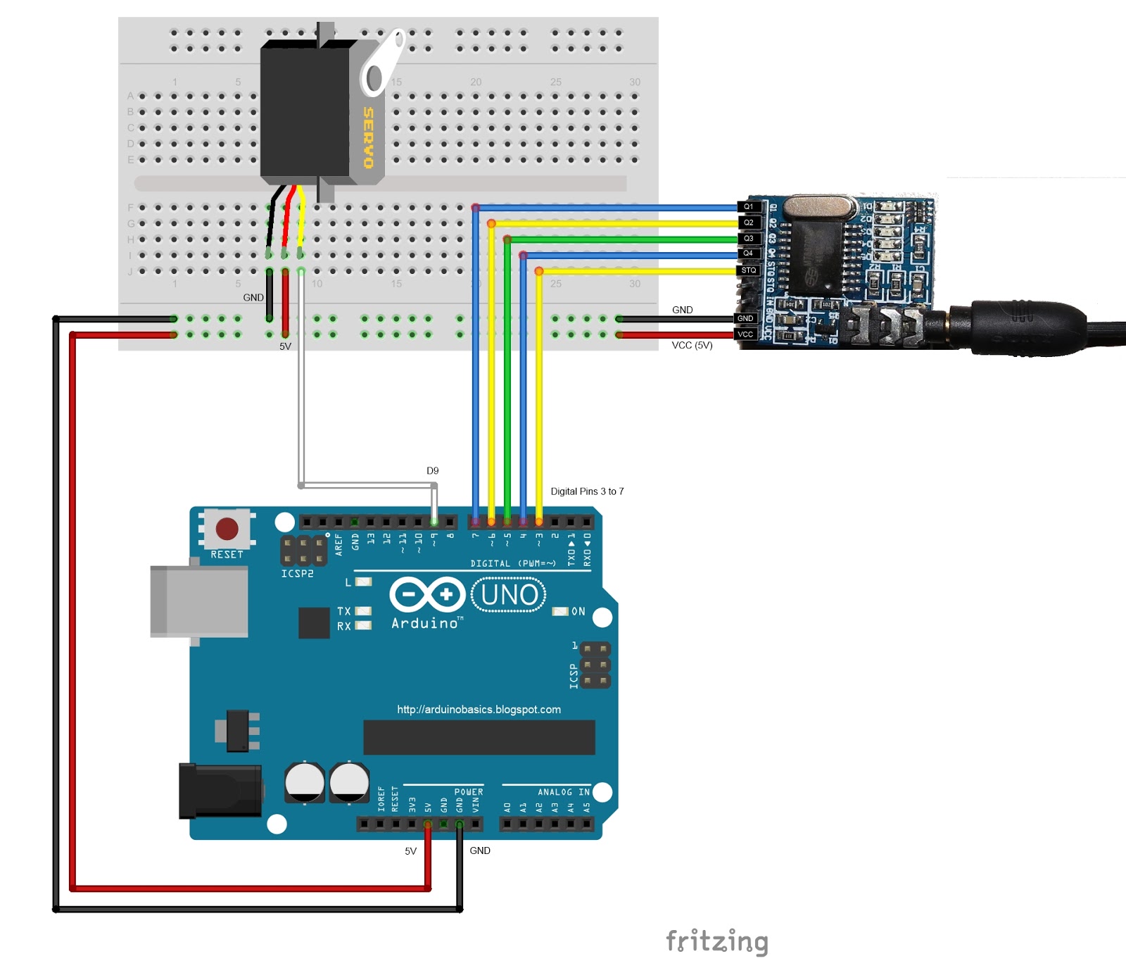
Fritzing sketch
The following diagram will show you how to wire everything together
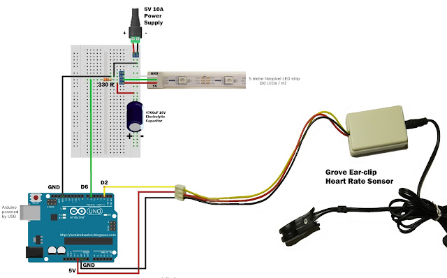
(click to enlarge)
Arduino Power considerations
Please note that the Arduino is powered by a USB cable.
If you plan to power the Arduino from your power supply, you will need to disconnect the USB cable from the Arduino FIRST, then connect a wire from the 5V line on the Power supply to the 5V pin on the Arduino. Do NOT connect the USB cable to the Arduino while the 5V wire is connected to the Arduino.
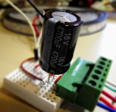
Large Capacitor
Adafruit also recommend the use of a large capacitor across the + and - terminals of the LED strip to "prevent the initial onrush of current from damaging the pixels". Adafruit recommends a capacitor that is 1000uF, 6.3V or higher. I used a 4700uF 16V Electrolytic Capacitor.
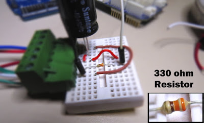
Resistor on Data Pin
Another recommendation from
Adafruit is to place a "300 to 500 Ohm resistor" between the Arduino's data pin and the data input on the first NeoPixel to prevent voltage spikes that can damage the first pixel. I used a 330 Ohm resistor.
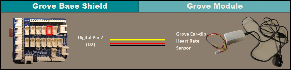
Grove Ear-clip heart rate sensor connection
The Grove Base shield makes it easy to connect Grove modules to the Arduino. If you have a Grove Base shield, you will need to connect the Ear-clip heart rate sensor to Digital pin 2 as per the diagram below.
Completed construction
Once you have everything connected, you can plug the USB cable into the Arduino, and turn on the LED power supply. Attach the ear-clip to your ear (or to your finger) and allow a few seconds to allow the sensor to register your pulse. The LED strip will light up with every heart beat with an animation that moves from one end of the strip to the other in just three heart beats. When the ear-clip is not connected to your ear or finger, the LEDs should remain off. However, the ear clip may "trigger" a heart beat when opening or closing the clip.
Here is a picture of all the components (fully assembled).

Concluding comments
This very affordable LED strip allows you to create amazing animations over a greater distance. I thought that having less LEDs per metre would make the animations look "jittery", but I was wrong, they look amazing. One of the good things about this strip is the amount of space between each Neopixel, allowing you to easily cut and join the strip to the size and shape you need.
This LED strip is compatible with the FastLED library, which makes for easy LED animation programming. While I used this LED strip to display my heart beat, you could just as easily use it to display the output of any other sensor attached to the Arduino.
This project would not have been possible without
OpenLab's collaborative effort.
Please visit their site for more cool projects.
However, if you do not have a google profile...
Feel free to share this page with your friends in any way you see fit.