

Getting Started with the Keyes ESP-13 WiFi Shield
Description
This tutorial will help you get started with the KEYES ESP-13 WiFi Shield.
The ESP-13 WiFi Shield is compatible with an Arduino UNO and has the same form-factor. Essentially this shield will give your Arduino project WiFi capabilities. While it interfaces nicely with the Arduino, it can operate without it. However, if I were planning on using the shield independantly, then I probably would opt for an ESP module rather than a shield.
I bought my shield from Jaycar (CAT.NO: XC4614), however you can get it much cheaper from other online retailers at about a quarter of the price. The instructions on the Jaycar website are not that good, and at first I thought I had bought myself a useless product. It just didn't seem to work regardless of what I tried. There were some tutorials online that gave me hope, only to find that my shield was not quite the same and therefore I did not get the same results. But after countless hours of trial and error and patching various bits of knowledge together, I finally worked out how to use this shield. Everything has fallen into place. And it is easier that you would think... let me show you how.
Parts Required
- Arduino UNO (or compatible board)
- KEYES ESP-13 WiFi Shield - from Jaycar (Cat. No: XC4614)
- USB cable - to connect Arduino to Computer
- 4 wires: 4 x Male to Male connectors
Libraries and IDE
Arduino IDE
While there are many Arduino IDE alternatives out there, I would recommend that you use the official Arduino IDE for this project. I used the official Arduino IDE app (v1.8.5) for Windows 10.
Make sure to get the most up-to-date version for your operating system here.

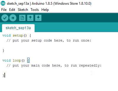
Upload BareMinimum Sketch
Upload a BareMinimum Sketch to the Arduino UNO (or compatible board) before making any connections to the ESP-13. We want to upload the BareMinimum sketch because we don't want the Arduino UNO interfering with our setup in anyway. Here is how to do that:
- Start your Arduino IDE
- Connect the Arduino UNO to the Computer using a USB cable
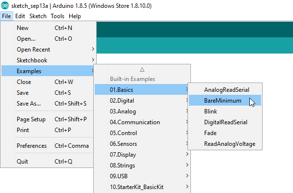
- Select: File > New (or Ctrl + N)
- Select: File > Examples > 01.Basics > BareMinimum
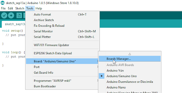
- Select: Tools > Board > Arduino/Genuino UNO
- Select: Tools > Port > COM4 (Your Arduino may be on a different COM port)
- Select: Sketch > Upload (or Ctrl + U) - or click on right arrow symbol
- After the sketch has uploded. Disconnect the USB cable from the computer/Arduino.
IDE Configuration for ESP-13
Now for the fun part. The ESP-13 WiFi Shield is itself a microcontroller, however, the Arduino IDE is not by default, configured to communicate with or program the ESP-13 WiFi Shield. We are about to change that:
- Select File > Preferences from the Arduino IDE menu (or Ctrl+Comma)
- Insert the following text into the Additional Boards Manager URLs field:
If there is a URL in that space already, then insert a comma, and append the URL to the end:http://arduino.esp8266.com/stable/package_esp8266com_index.json
- Once the URL is added, press OK.
This will allow us to install the ESP8266 package in the next step.

Installing the ESP8266 board
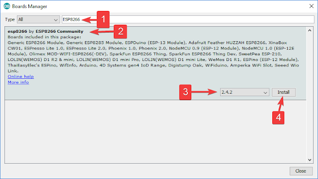
- Select: Tools > Board: "xxxx" > Boards Manager
- Search for ESP8266 using the Search bar
- Select the "esp8266 by ESP8266 Community" board from the list.
- Select the latest or most up-to-date version from the drop-down box (eg. 2.4.2)
- Press the Install button.
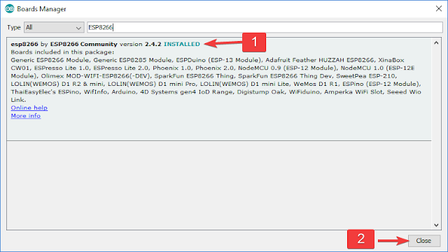
- Make sure that the esp8266 board is installed. Then press the "Close" button
- Choose the ESPDuino(ESP-13 Module) from the ESP8266 Modules list:
Tools > Board: "xxxx" > ESPDuino(ESP-13 Module)

ESP-13 Flash Settings
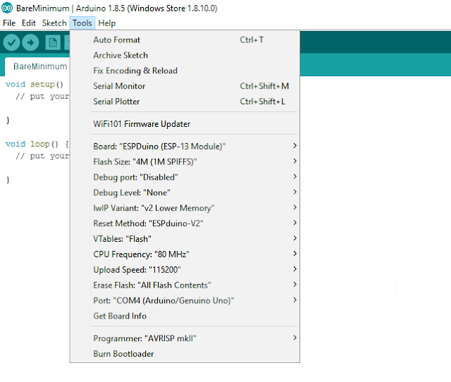
You will then want to check that you have the following settings in the Tools menu of the Arduino IDE:
- Board: "ESPDuino (ESP-13 Module)"
- Flash Size: "4M (1M SPIFFS)"
- Debug port: "Disabled"
- Debug Level: "None"
- IwIP Variant: "v2 Lower Memory"
- Reset Method: "ESPduino-V2"
- VTables: "Flash"
- CPU Frequency: "80MHz"
- Upload Speed: "115200"
- Erase Flash: Only Sketch
- Port: - (we will select that later)
The Arduino IDE is now able to communicate with, and program the ESP-13 WiFi shield.
Now let us have a look at how to use the default AI-Thinker AT-firmware that comes pre-loaded on the shield.
Preparing the WiFi Shield for Communication
The Keyes ESP-13 WiFi shield comes pre-loaded with AI-Thinker firmware. I thought I just had to place the WiFi shield on top of the Arduino UNO, and I should be able to send through some AT commands via the Serial monitor. Yes - it is a shield, and yes, we will use it as a shield later on, but if you want to use the Serial monitor while the shield is sitting on-top of the Arduino UNO, you will need to make use of the SoftwareSerial library. You can go down this path, but it is cumbersome. There is a better way. We will still need the Arduino UNO, but we need to connect it to the ESP-13 Shield in the following manner:
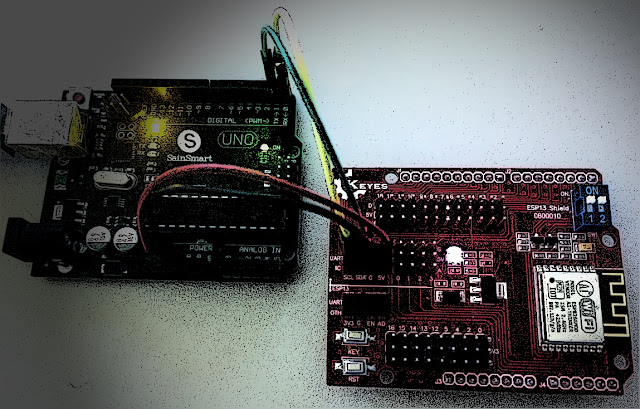
Wire Connections
- Make sure that the Arduino UNO is OFF (i.e. not connected to power or USB port)
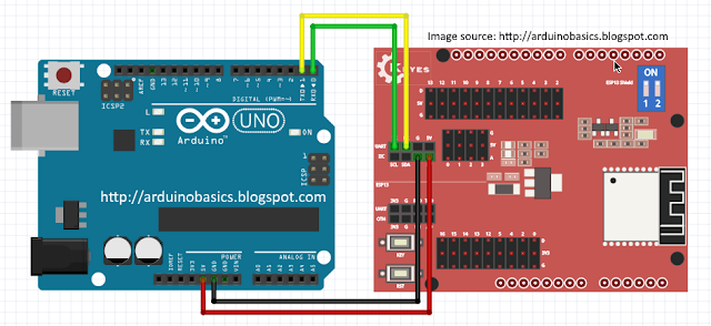
- Place the ESP-13 WiFi shield NEXT TO the Arduino UNO
- Connect a Red wire between 5V on Arduino UNO, and 5V (Arduino side) of the ESP-13 shield
- Connect a Black wire between GND on Arduino, and G (Arduino side) of the ESP-13 shield
- Connect a Green wire between D0(RX) on Arduino, and TX (UART - Arduino side) of ESP-13
- Connect a Yellow wire between D1(TX) on Arduino, and RX (UART - Arduino side) of ESP-13
- Make sure that both of the switches on the ESP-13 WiFi Shield are in the "ON" position.
Serial Monitor Setup
- Plug the USB cable into the computer, and the other end into the Arduino
- You should see a Red LED ignite on the ESP-13 Shield.
- In your Arduino IDE, make sure the correct COM port is selected:
Tools > Port > COM4 (Arduino/Genuino UNO) - your port may be different. - The IDE recognises that an Arduino is using that COM port, even though ESP-13 Board selected
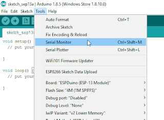
- Open the Serial Monitor: Tools > Serial Monitor (or Ctrl + Shift + M)
- Select: Both NL & CR from the drop-down box at the bottom right side of the Serial Monitor.
- Select: 115200 baud from the other drop-down box in the Serial Monitor window.
- Press the RESET (RST) button on the bottom left of the ESP-13 WiFi Shield.
- You may see some garbled information come through, but you should see "Ai-Thinker Technology Co.,Ltd" and "ready" messages in the debug window.
- You can now send through your AT-commands to the ESP-13 WiFi shield.
Using default AI-Thinker AT-firmware
Now is a good time to test the AI-Thinker AT-firmware. It is possible to program the Arduino to send a sequence of AT commands to the ESP-13 WiFi Shield, but for demonstration purposes, I will show you how to send the commands manually via the Serial monitor.
- If you see "ready" within the Serial Monitor window, the ESP-13 is ready to receive AT commands.
- Type: AT into the box at the top and press the Send button (or Enter)
- You should now see the AT command in the debug window, and a response "OK"
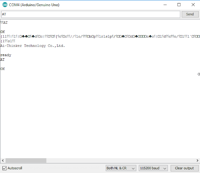
If you received the OK message, then your communication with the ESP-13 was successful.
A good list of AT commands and explanations can be found here.
Another list of AT commands can be found here.
The commands allow you to test, query and configure the ESP-13 shield. Essentially a command-line interface. Try out the following commands to get a feel for these functions/queries. The commands are in bold, and I placed some of the responses that I got in the line below.
- AT
Response: OK - AT+RST
This resets the ESP-13 board. It provides some info about the board. - AT+GMR
AT version: 0.40.0.0 (Aug 8 2015)
SDK version: 1.3.0
Ai-Thinker Technology Co.,Ltd.
Build:1.3.0.2 Sep 11 2015
- AT+CIFSR
+CIFSR:APIP, "192.168.4.1" - AT+CWMODE?
+CWMODE:2 [1=STA, 2=AP, 3=BOTH] - AT+CWLAP
ERROR - AT+CWMODE=3
- AT+CWLAP
+CWLAP:(3,"MYACCESSPOINT", -53, "xx:xx:xx:xx:xx:xx",6,-12)
So there you go. Now you have everything need to configure your ESP-13 WiFi shield. Once you are tired of playing around with AT commands, I will show you how to re-program and upload sketches to the ESP-13 WiFi Shield, and use it the way it was designed to be used (i.e. as a shield). To upload sketches to the Shield, you will need one extra wire. But I think that deserves to be another tutorial. Stay tuned.
Summary
In this tutorial, I showed you how to configure your Arduino IDE for the ESP-13 shield. I also explained how to wire the ESP-13 WiFi shield so that you can communicate with it using the Serial monitor. I hope this tutorial helped you in some way. If it did, please let me know in the comments below. I will be following up with another tutorial, which will show you how to upload sketches to the ESP-13 WiFi Shield, and free it from your computer.
Social Media
You can find me on various social networks:
Visit my ArduinoBasics Google + page.
Follow me on Twitter by looking for ScottC @ArduinoBasics.
I can also be found on Pinterest and Instagram.
Have a look at my videos on my YouTube channel.
