Posts with «uncategorized» label

Learn Arduino with “Arduino Workshop, 2nd Edition: A Hands-on Introduction with 65 Projects”

After eight years and much feedback from various readers, I’m proud to offer the second edition of my first book “Arduino Workshop”, from No Starch Press. This is a revised update to this very popular book which is aimed at any person who wants to make electronic devices using the Arduino platform – but has no experience in electronics, programming or microcontrollers.

The reader doesn’t need to buy or read any other book first to get started, from the beginning they are introduced to the basic concepts, required software installation and then introduced to various topics from blinking an LED to controlling devices remotely via a cellular phone.

Contents include:

Chapter 1: Getting Started
Chapter 2: Exploring the Arduino Board and the IDE
Chapter 3: First Steps
Chapter 4: Building Blocks
Chapter 5: Working with Functions
Chapter 6: Numbers, Variables, and Arithmetic
Chapter 7: Expanding Your Arduino
Chapter 8: LED Numeric Displays and Matrices
Chapter 9: Liquid Crystal Displays
Chapter 10: Creating your own Arduino Libraries
Chapter 11: Numeric Keypads
Chapter 12: Accepting User Input with Touchscreens
Chapter 13: Meet the Arduino Family
Chapter 14: Motors and Movement
Chapter 15: Using GPS with Your Arduino
Chapter 16: Wireless Data
Chapter 17: Infrared Remote Control
Chapter 18: Reading RFID Tags
Chapter 19: Data Buses
Chapter 20: Real-time Clocks
Chapter 21: The Internet
Chapter 22: Cellular Communications

You can also review the entire book index from here.

Once the reader has progressed through “Arduino Workshop”, I have found that many people use it as a reference guide for various topics, and saves them time and effort. Instead of searching randomly for various videos, web pages or whatnot – this book offers solid, tried-and-tested information that can be relied on without worry.

Readers of the first edition will also be introduced to new chapters in this edition, such as learning how to create your own Arduino libraries, introduction to the new v2.0 IDE, using new types of LED displays, remote control of devices with LoRA wireless shields, an updated cellular chapter that uses contemporary 3G wireless, and more.

The book is printed using a convenient lie-flat technology, so you can have the book open to your side and not worry about the pages flapping about and losing your position while working on your projects. All the required code (or Arduino “sketches”) are included in the book, however you can also download them along with a list of parts and supplier information from the book’s website.

The Arduino platform in my opinion is still the easiest and most approachable way of learning about electronics and microcontrollers, and opens up a whole new world of creativity or even the pathway to a career in technology, and a copy of “Arduino Workshop” is the best guide to this world.

You can learn more about the book and order from the No Starch Press online store, amazon, kindle, or your preferred bookseller. Orders from No Starch Press also include a free electronic copy so you can get started immediately.

And whatever you do, have fun and make something!

Tronixstuff 23 Jun 00:51

Together, Let’s Make COVID-19 History

Combating COVID-19 Conference: A Collaborative Arduino Community Initiative 
to take place on April 2nd at 5pm CET

Humanity is facing one of the most trying events in its history and as technologists, makers and designers we are asking ourselves how can we help. 

How can we contribute to the efforts to save lives, to help our fellow human beings?

All of us have been thinking about this and observing what was going on in the world.

We have seen communities, including the Arduino community, trying to design devices that would help hospitals cope with the lack of equipment; we’ve seen people firing up their imagination and their 3d printers in an effort to build something that could save even a single human life.

Having noticed that a large number of these efforts are using Arduino technology we reached out to a number of these communities to offer our help, donate some hardware, provide engineering support and do whatever we can considering that we are a small company.

One thing that was striking to us is the large amount of duplication in the work people are doing – many people are spending valuable time trying to overcome similar challenges in their design, rather than sharing their solution to the benefit of all and moving on to the next hurdle. Also that there are different teams with different strengths and skill sets that would be better working together than apart.

We must do better, be more effective, work together and merge efforts to solve these problems and reach our common goal quicker and more efficiently.

Because of all of this we want to invite as many of these projects as possible to an online gathering, to get people talking, to offer help on how to design and make hardware, how to think about the software, and how to scale manufacturing (we would like to share our knowledge in making tens of thousands of open source boards per week). Finally and most importantly we must take guidance from  medical professionals so that they can steer requirements and validate the designs so our efforts have the most positive impact. 

Join us online on April, 2nd to understand how we can work together to do better together, and Together – Let’s Make Covid-19 History

David Cuartielles, Massimo Banzi co-founders of Arduino (on behalf of Arduino)

Combating COVID-19 Conference: A Collaborative Arduino Community Initiative
will take place on April 2nd at 17.00 CET.

This is an open invitation to anyone currently using Arduino compatible devices within a project to design and manufacture ventilators, respirators or other devices to combat COVID-19. Be you a doctor, an academic, a professional company/researcher or an innovator you are more than welcome to join the conference. 

The conference will be hosted in Zoom (link available soon), with the ability to interact with Arduino and other members on the conference via Discord (free download here). 

There are different ways to participate in the conference; you can present your Arduino based project to combat COVID-19, support other community projects or provide expert advice – we are all stronger together.

(N.B. if you want to present and share your project, please complete this form by 12.00 (noon) CET on April 2nd)

More information on the conference will be available soon, in the meantime you can learn more about Arduino’s overall response to COVID-19 emergency here.

The Arduino Fundamentals Certification Exam is now available in Spanish and Italian!

For enthusiasts, the Fundamentals Exam is the first tier in the Arduino Certification Program (ACP), designed to test entrants knowledge in Arduino-related electronics, programming, and physical computing.

The exam is available for everyone interested in officially certifying their skills and knowledge on Arduino, that could, for example, be referred to in a resume for academic or professional purposes.

Get your students, colleagues and friends certified!

The Fundamentals Exam is now also open to schools, academic institutions, universities, and companies that are interested in getting their students and employees officially certified!

The Fundamentals Certification offers the right balance of academic excellence and real world skills to give students the confidence and motivation they need to succeed both in educational and professional environments.

It is a great opportunity for companies who are interested in certifying their employees to refresh and add new skills to their repertoire.

Want to learn more? Additional information can be found here.

El examen de Certificación Fundamentals, está ahora disponible en Español e Italiano

Para entusiastas, el examen de Certificación Fundamentals, es el primer nivel del Programa de certificación Arduino (ACP), diseñado para evaluar el conocimiento de los participantes en electrónica, programación y computación física relacionadas con Arduino.

El examen está disponible para todos los interesados ??en certificar oficialmente sus habilidades y conocimientos en Arduino, que podrían, por ejemplo, mencionarse en un currículum con fines académicos o profesionales.

¡Certifica a tus estudiantes, colegas y equipo de trabajo!

La certificación también está disponible para escuelas, instituciones académicas, universidades y empresas que estén interesadas en certificar oficialmente a sus estudiantes y equipo de trabajo.

La Certificación Fundamentals ofrece el equilibrio adecuado entre excelencia académica y habilidades del mundo real, para brindar a los estudiantes la confianza y la motivación que necesitan para tener éxito tanto en entornos académicos como profesionales.

También es una gran posibilidad para compañías que están interesadas en certificar a su equipo de trabajo para actualizar y agregar nuevas habilidades a su repertorio.

Para saber más visita: https://store.arduino.cc/digital/cert_fundamentals.

Siamo lieti di annunciare che l’esame per la certificazione Arduino Fundamentals è da adesso disponibile anche in spagnolo e italiano! 

Desideriamo rendere accessibile la Certificazione alle scuole, alle istitutuzioni, università e aziende che siano interessate a certificare ufficialmente i propri studenti e dipendenti! La certificazione Arduino Fundamentals offre il giusto equilibrio fra l’acquisizione di abilità accademiche e lavorative, fornendo agli studenti la sicurezza e la motivazione necessarie per riuscire nel mondo accademico e professionale. E’ inoltre un increndibile possibilità per le aziende interessate ad aggionarne, migliorare e/o accrescere le capacità dei propri dipendenti.

Per saperne di più, visitate: https://store.arduino.cc/digital/cert_fundamentals.

Researchers have developed self-healing soft electronics

While flexible electronics can pose certain advantages, they are often subject to a rather short life, and can be difficult if not impossible to repair. As a solution to this conundrum, researchers from Carnegie Mellon University and the University of Tokyo have been exploring a novel material that can fuse itself together automatically, and conduct electricity.

The composite material is called MWCNTs-PBS, or multi-walled carbon nanotubes surrounded by a flexible polymer polyborosiloxane outer region. When two sections need to be attached, they’re simply pressed together and like magic it forms an electrical and mechanical bond. 

Tests performed with the help of an Arduino Mega include pressure and touch sensing, as well as cut detection. It will be interesting to see how this technology advances in the future, perhaps leading to a day when devices just ‘heal’ themselves!

Living things in nature have long been utilizing the ability to “heal” their wounds on the soft bodies to survive in the outer environment. In order to impart this self-healing property to our daily life interface, we propose Self-healing UI, a soft-bodied interface that can intrinsically self-heal damages without external stimuli or glue. The key material to achieving Self-healing UI is MWCNTs-PBS, a composite material of a self-healing polymer polyborosiloxane (PBS) and a filler material multi-walled carbon nanotubes (MWCNTs), which retains mechanical and electrical self-healability. We developed a hybrid model that combines PBS, MWCNTs-PBS, and other common soft materials including fabric and silicone to build interface devices with self-healing, sensing, and actuation capability. These devices were implemented by layer-by-layer stacking fabrication without glue or any post-processing, by leveraging the materials’ inherent self-healing property between two layers. We then demonstrated sensing primitives and interactive applications that extend the design space of shape-changing interfaces with their ability to transform, con- form, reconfigure, heal, and fuse, which we believe can enrich the toolbox of human-computer interaction (HCI). 

Arduino Blog 09 Nov 00:42

Tutorial – Using the TCA9548A 1-to-8 I2C Multiplexer Breakout with Arduino

Now and again you may find yourself needing to use more than one device with the same I2C bus address with your Arduino.

Such as four OLEDs for a large display – or seven temperature sensors that are wired across a chicken hatchling coop.

These types of problems can be solved with the TCA9548A 1-to-8 I2C Multiplexer Breakout, and in this guide we’ll run through the how to make it happen with some example devices.

Getting Started

First, consider the TCA9548A itself. It is the gateway between your Arduino and eight separate I2C buses. You have a single bus on one side, connected to your Arduino.

On the other side of the TCA9548A, you have eight I2C buses, and only one of these can be connected to the Arduino at a time. For example (from the data sheet):

The TCA9548 can operate on voltages between 1.8 and 5V DC… and operate with devices that have operating voltages between 1.8 and 5V DC. This is very convenient, as (for example) you can use devices made for 3.3V operation with 5V Arduinos, or vice versa. Awesome. So let’s get started.

The breakout board includes inline header pins, which are not soldered to the board. So you need to do that. An easy way to line up the pins properly is to drop them into a soldereless breadboard, as such:

Then after a moment or two of soldering, you’re ready to use:

Next, insert your module into a solderless breadboard and wire it up as shown:

We are using the red and blue vertical strips on the breadboard as 5V and GND respectively. Finally, we connect the 5V and GND from the Arduino to the solderless breadboard, and A4/A5 to SDA/SCL respectively on the breakout board:

The electrical connections are as follows (Module — Arduino):

  • Vin to 5V
  • GND to GND
  • A0 to GND
  • A1 to GND
  • A2 to GND
  • SDA to A4
  • SCL to A5

Next, we consider the I2C bus address for the TCA9548A. Using the wiring setup shown above, the address is set to 0x70. You only need to change this if one of your other devices also has an address of 0x70, as shown in the next step.

Changing the I2C address of the TCA9548A

The bus address of the TCA9548A is changed using the connections to the A0, A1 and A2 pins. By default in the tutorial we use 0x70, by wiring A0~A2 to GND (known as LOW). Using the table below, you can reconfigure to an address between 0x70 and 0x77 by matching the inputs to HIGH (5V) or LOW (GND):

Testing 

Before we get too excited, now is a good time to test our wiring to ensure the Arduino can communicate with the TCA9548A. We’ll do this by running an I2C scanner sketch, which returns the bus address of a connected device.

Copy and paste this sketch into your Arduino IDE and upload it to your board. Then, open the serial monitor and set the data rate to 115200. You should be presented with something like the following:

As you can see, our scanner returned an address of 0x70, which matches the wiring described in the bus address table mentioned earlier. If you did not find success, unplug the Arduino from the computer and double-check your wiring – then try again.

Controlling the bus selector

Using the TCA9548A is your sketch is not complex at all, it only requires one step before using your I2C device as normal. That extra step is to instruct the TCA9548A to use one of the eight buses that it controls.

To do this, we send a byte of data to the TCA9548A’s bus register which represents which of the eight buses we want to use. Each bit of the byte is used to turn the bus on or off, with the MSB (most significant bit) for bus 7, and the LSB (least significant bit) for bus 0.

For example, if you sent:

0b00000001 (in binary) or 0 in decimal

… this would activate bus zero.

Or if you sent:

0b00010000 (in binary)

… this would activate bus five.

Once you select a bus, the TCA9548A channels all data in and out of the bus to the Arduino on the selected bus. You only need to send the bus selection data when you want to change buses. We’ll demonstrate that later.

So to make life easier, we can use a little function to easily select the required bus:

void TCA9548A(uint8_t bus)
{
  Wire.beginTransmission(0x70);  // TCA9548A address is 0x70
  Wire.write(1 << bus);          // send byte to select bus
  Wire.endTransmission();
}

This function accepts a bus number and places a “1” in the TCA9548A’s bus register matching our requirements. Then, you simply slip this function right before needing to access a device on a particular I2C bus. For example, a device on bus 0:

TCA9548A(0);

… or a device on bus 6:

TCA9548A(6);

A quick note about pull-up resistors

You still need to use pull-up resistors on the eight I2C buses eminating from the TCA9548A. If you’re using an assembled module, such as our example devices – they will have the resistors – so don’t panic.

If not, check the data sheets for your devices to determine the appropriate pull-up resistors value. If this information isn’t available, try 10k0 resistors.

Controlling our first device

Our first example device is the tiny 0.49″ OLED display. It is has four connections, which are wired as follows (OLED — TCA9548A/Arduino):

  • GND to GND
  • Vcc to Arduino 3.3V
  • CL to TCA9548A SC0 (bus #0, clock pin)
  • DA to TCA9548A SD1 (bus #0, data pin)

The OLED runs from 3.3V, so that’s why we’re powering it directly from the Arduino’s 3.3V pin.

Now, copy and upload this sketch to your Arduino, and after a moment the OLED will display some numbers counting down in various amounts:

So how did that work? We inserted out bus selection function at line 9 of the sketch, then called the function in at line 26 to tell the TCA9548A that we wanted to use I2C bus zero. Then the rest of the sketch used the OLED as normal.

Controlling two devices

Let’s add another device, a BMP180 barometric pressure sensor module. We’ll connect this to I2C bus number seven on the TCA5948A. There are four connections, which are wired as follows (BMP180 — TCA9548A/Arduino):

  • GND to GND
  • Vcc to Arduino 3.3V
  • CL to TCA9548A SC0 (bus #7, clock pin)
  • DA to TCA9548A SD1 (bus #7, data pin)

Now, copy and upload this sketch to the Arduino, and after a moment the OLED will display the ambient temperature from the BMP180 in whole degrees Celsius. This is demonstrated in the following video (finger is placed on the BMP180 for force a rise in temperature):

So how did that work? We set up the libraries and required code for the OLED, BMP180 and TCA5948A as usual.

We need to intialise the BMP180, so this is done at line 29 – where we select the I2C bus 7 before initiating the BMP180.

The the sketch operates. On line 40 we again request I2C bus 7 from the TCA9548A, then get the temperature from the BMP180.

On line 44 we request I2C bus 0 from the TCA9548A, and then display the temperature on the OLED. Then repeat.

A quick note about the reset pin

More advanced users will be happy to know they can reset the TCA9548A status, to recover from a bus-fault condition. To do this, simply drop the RESET pin LOW (that is, connect it to GND).

Where to from here? 

You can now understand through our worked example how easy it is to use the TCA9548A and access eight secondary I2C buses through the one bus from your Arduino. Don’t forget that the TCA9548A also does double-duty as a level converter, thereby increasing its value to you.

And that’s all for now. This post brought to you by pmdway.com – everything for makers and electronics enthusiasts, with free delivery worldwide.

To keep up to date with new posts at tronixstuff.com, please subscribe to the mailing list in the box on the right, or follow us on twitter @tronixstuff.

Tronixstuff 29 Oct 04:57

Tutorial – Using the 0.96″ 80 x 160 Full Color IPS LCD Module with Arduino

The purpose of this guide is to get your 0.96″ color LCD display successfully operating with your Arduino, so you can move forward and experiment and explore further types of operation with the display. This includes installing the Arduino library, making a succesful board connection and running a demonstration sketch.

Although you can use the display with an Arduino Uno or other boad with an ATmega328-series microcontroller – this isn’t recommended for especially large projects. The library eats up a fair amount of flash memory – around 60% in most cases.

So if you’re running larger projects we recommend using an Arduino Mega or Due-compatible board due to the increased amount of flash memory in their host microcontrollers.

Installing the Arduino library

So let’s get started. We’ll first install the Arduino library then move on to hardware connection and then operating the display.

(As the display uses the ST7735S controller IC, you may be tempted to use the default TFT library included with the Arduino IDE – however it isn’t that reliable. Instead, please follow the instructions below). 

First – download the special Arduino library for your display and save it into your Downloads or a temp folder.

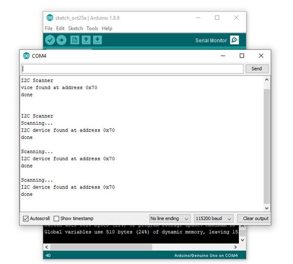
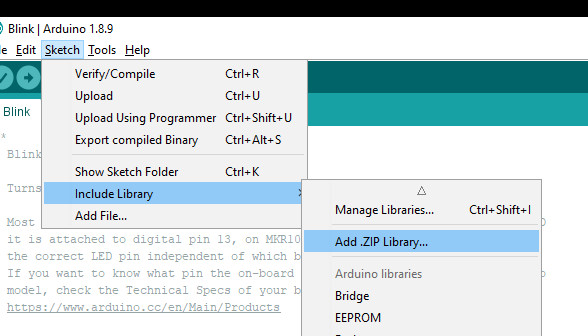
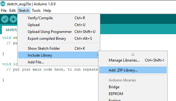
Next – open the Arduino IDE and select the Sketch > Include Library > Add .ZIP library option as shown below:

A dialog box will open – navigate to and select the zip file you downloaded earlier. After a moment or two the IDE will then install the library.

Please check that the library has been installed – to do this, select the Sketch > Include Library option in the IDE and scroll down the long menu until you see “ER-TFTM0.96-1” as shown below:

Once that has been successful, you can wire up your display.

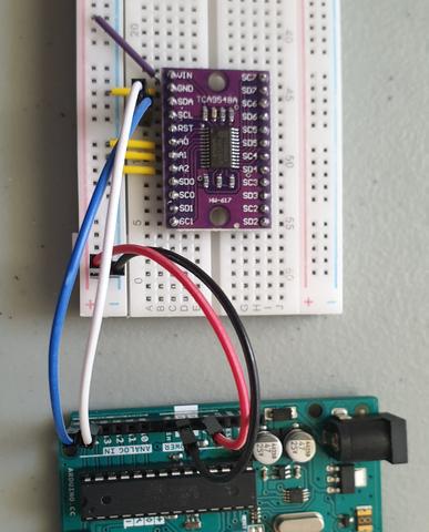
Connecting the display to your Arduino

The display uses the SPI data bus for communication, and is a 3.3V board. You can use it with an Arduino or other 5V board as the logic is tolerant of higher voltages.

Arduino to Display

GND ----- GND (GND)
3.3V ---- Vcc (3.3V power supply)
D13 ----- SCL (SPI bus clock)
D11 ----- SDA (SPI bus data out from Arduino)
D10 ----- CS (SPI bus "Chip Select")
D9 ------ DC (Data instruction select pin)
D8 ------ RES (reset input)

If your Arduino has different pinouts than the Uno, locate the SPI pins for your board and modify as appropriate.

Demonstration sketch

Open a new sketch in the IDE, then copy and paste the following sketch into the IDE:

// https://pmdway.com/products/0-96-80-x-160-full-color-lcd-module
#include <UTFT.h>

// Declare which fonts we will be using
extern uint8_t SmallFont[];

// Initialize display
// Library only supports software SPI at this time
//NOTE: support  DUE , MEGA , UNO 
//SDI=11  SCL=13  /CS =10  /RST=8  D/C=9
UTFT myGLCD(ST7735S_4L_80160,11,13,10,8,9);    //LCD:  4Line  serial interface      SDI  SCL  /CS  /RST  D/C    NOTE:Only support  DUE   MEGA  UNO

// Declare which fonts we will be using
extern uint8_t BigFont[];

int color = 0;
word colorlist[] = {VGA_WHITE, VGA_BLACK, VGA_RED, VGA_BLUE, VGA_GREEN, VGA_FUCHSIA, VGA_YELLOW, VGA_AQUA};
int  bsize = 4;

void drawColorMarkerAndBrushSize(int col)
{
  myGLCD.setColor(VGA_BLACK);
  myGLCD.fillRect(25, 0, 31, 239);
  myGLCD.fillRect(myGLCD.getDisplayXSize()-31, 161, myGLCD.getDisplayXSize()-1, 191);
  myGLCD.setColor(VGA_WHITE);
  myGLCD.drawPixel(25, (col*30)+15);
  for (int i=1; i<7; i++)
    myGLCD.drawLine(25+i, ((col*30)+15)-i, 25+i, ((col*30)+15)+i);
  
  if (color==1)
    myGLCD.setColor(VGA_WHITE);
  else
    myGLCD.setColor(colorlist[col]);
  if (bsize==1)
    myGLCD.drawPixel(myGLCD.getDisplayXSize()-15, 177);
  else
    myGLCD.fillCircle(myGLCD.getDisplayXSize()-15, 177, bsize);
    
  myGLCD.setColor(colorlist[col]);
}
void setup()
{
  randomSeed(analogRead(0));
  
// Setup the LCD
  myGLCD.InitLCD();
  myGLCD.setFont(SmallFont);
}

void loop()
{
  int buf[158];
  int x, x2;
  int y, y2;
  int r;

// Clear the screen and draw the frame
  myGLCD.clrScr();

  myGLCD.setColor(255, 0, 0);
  myGLCD.fillRect(0, 0, 159, 13);
  myGLCD.setColor(64, 64, 64);
  myGLCD.fillRect(0, 114, 159, 127);
  myGLCD.setColor(255, 255, 255);
  myGLCD.setBackColor(255, 0, 0);
  myGLCD.print("pmdway.com.", CENTER, 1);
  myGLCD.setBackColor(64, 64, 64);
  myGLCD.setColor(255,255,0);
  myGLCD.print("pmdway.com", LEFT, 114);


  myGLCD.setColor(0, 0, 255);
  myGLCD.drawRect(0, 13, 159, 113);

// Draw crosshairs
  myGLCD.setColor(0, 0, 255);
  myGLCD.setBackColor(0, 0, 0);
  myGLCD.drawLine(79, 14, 79, 113);
  myGLCD.drawLine(1, 63, 158, 63);
  
 myGLCD.setColor(0, 0, 255);
 myGLCD.drawLine(0, 79, 159, 79);
 
  for (int i=9; i<150; i+=10)
    myGLCD.drawLine(i, 61, i, 65);
  for (int i=19; i<110; i+=10)
    myGLCD.drawLine(77, i, 81, i);
    

// Draw sin-, cos- and tan-lines  
  myGLCD.setColor(0,255,255);
  myGLCD.print("Sin", 5, 15);
  for (int i=1; i<158; i++)
  {
    myGLCD.drawPixel(i,63+(sin(((i*2.27)*3.14)/180)*40));
  }
  
  myGLCD.setColor(255,0,0);
  myGLCD.print("Cos", 5, 27);
  for (int i=1; i<158; i++)
  {
    myGLCD.drawPixel(i,63+(cos(((i*2.27)*3.14)/180)*40));
  }

  myGLCD.setColor(255,255,0);
  myGLCD.print("Tan", 5, 39);
  for (int i=1; i<158; i++)
  {
    myGLCD.drawPixel(i,63+(tan(((i*2.27)*3.14)/180)));
  }

  delay(2000);

  myGLCD.setColor(0,0,0);
  myGLCD.fillRect(1,14,158,113);
  myGLCD.setColor(0, 0, 255);
  myGLCD.setBackColor(0, 0, 0);
  myGLCD.drawLine(79, 14, 79, 113);
  myGLCD.drawLine(1, 63, 158, 63);

 myGLCD.setColor(0, 0, 255);
 myGLCD.drawLine(0, 79, 159, 79);  

// Draw a moving sinewave
  x=1;
  for (int i=1; i<(158*20); i++) 
  {
    x++;
    if (x==159)
      x=1;
    if (i>159)
    {
      if ((x==79)||(buf[x-1]==63))
        myGLCD.setColor(0,0,255);
      else
        myGLCD.setColor(0,0,0);
      myGLCD.drawPixel(x,buf[x-1]);
    }
    myGLCD.setColor(0,255,255);
    y=63+(sin(((i*2.5)*3.14)/180)*(40-(i / 100)));
    myGLCD.drawPixel(x,y);
    buf[x-1]=y;
  }

  delay(2000);
 
  myGLCD.setColor(0,0,0);
  myGLCD.fillRect(1,14,158,113);
  
 myGLCD.setColor(0, 0, 255);
 myGLCD.drawLine(0, 79, 159, 79);  

// Draw some filled rectangles
  for (int i=1; i<6; i++)
  {
    switch (i)
    {
      case 1:
        myGLCD.setColor(255,0,255);
        break;
      case 2:
        myGLCD.setColor(255,0,0);
        break;
      case 3:
        myGLCD.setColor(0,255,0);
        break;
      case 4:
        myGLCD.setColor(0,0,255);
        break;
      case 5:
        myGLCD.setColor(255,255,0);
        break;
    }
    myGLCD.fillRect(39+(i*10), 23+(i*10), 59+(i*10), 43+(i*10));
  }

  delay(2000);
  
  myGLCD.setColor(0,0,0);
  myGLCD.fillRect(1,14,158,113);
  myGLCD.setColor(0, 0, 255);
 myGLCD.drawLine(0, 79, 159, 79);   

// Draw some filled, rounded rectangles
  for (int i=1; i<6; i++)
  {
    switch (i)
    {
      case 1:
        myGLCD.setColor(255,0,255);
        break;
      case 2:
        myGLCD.setColor(255,0,0);
        break;
      case 3:
        myGLCD.setColor(0,255,0);
        break;
      case 4:
        myGLCD.setColor(0,0,255);
        break;
      case 5:
        myGLCD.setColor(255,255,0);
        break;
    }
    myGLCD.fillRoundRect(99-(i*10), 23+(i*10), 119-(i*10), 43+(i*10));
  }

  delay(2000);
  
  myGLCD.setColor(0,0,0);
  myGLCD.fillRect(1,14,158,113);

 myGLCD.setColor(0, 0, 255);
 myGLCD.drawLine(0, 79, 159, 79);  
// Draw some filled circles
  for (int i=1; i<6; i++)
  {
    switch (i)
    {
      case 1:
        myGLCD.setColor(255,0,255);
        break;
      case 2:
        myGLCD.setColor(255,0,0);
        break;
      case 3:
        myGLCD.setColor(0,255,0);
        break;
      case 4:
        myGLCD.setColor(0,0,255);
        break;
      case 5:
        myGLCD.setColor(255,255,0);
        break;
    }
    myGLCD.fillCircle(49+(i*10),33+(i*10), 15);
  }

  delay(2000);
    
  myGLCD.setColor(0,0,0);
  myGLCD.fillRect(1,14,158,113);
  
 myGLCD.setColor(0, 0, 255);
 myGLCD.drawLine(0, 79, 159, 79);    

// Draw some lines in a pattern
  myGLCD.setColor (255,0,0);
  for (int i=14; i<113; i+=5)
  {
    myGLCD.drawLine(1, i, (i*1.44)-10, 112);
  }
  myGLCD.setColor (255,0,0);
  for (int i=112; i>15; i-=5)
  {
    myGLCD.drawLine(158, i, (i*1.44)-12, 14);
  }
  myGLCD.setColor (0,255,255);
  for (int i=112; i>15; i-=5)
  {
    myGLCD.drawLine(1, i, 172-(i*1.44), 14);
  }
  myGLCD.setColor (0,255,255);
  for (int i=15; i<112; i+=5)
  {
    myGLCD.drawLine(158, i, 171-(i*1.44), 112);
  }

  delay(2000);
  
  myGLCD.setColor(0,0,0);
  myGLCD.fillRect(1,14,158,113);
  
 myGLCD.setColor(0, 0, 255);
 myGLCD.drawLine(0, 79, 159, 79);    

// Draw some random circles
  for (int i=0; i<100; i++)
  {
    myGLCD.setColor(random(255), random(255), random(255));
    x=22+random(116);
    y=35+random(57);
    r=random(20);
    myGLCD.drawCircle(x, y, r);
  }

  delay(2000);
  
  myGLCD.setColor(0,0,0);
  myGLCD.fillRect(1,14,158,113);
  
 myGLCD.setColor(0, 0, 255);
 myGLCD.drawLine(0, 79, 159, 79);    
  

// Draw some random rectangles
  for (int i=0; i<100; i++)
  {
    myGLCD.setColor(random(255), random(255), random(255));
    x=2+random(156);
    y=16+random(95);
    x2=2+random(156);
    y2=16+random(95);
    myGLCD.drawRect(x, y, x2, y2);
  }

  delay(2000);
  
  myGLCD.setColor(0,0,0);
  myGLCD.fillRect(1,14,158,113);
  
 myGLCD.setColor(0, 0, 255);
 myGLCD.drawLine(0, 79, 159, 79);    

// Draw some random rounded rectangles
  for (int i=0; i<100; i++)
  {
    myGLCD.setColor(random(255), random(255), random(255));
    x=2+random(156);
    y=16+random(95);
    x2=2+random(156);
    y2=16+random(95);
    myGLCD.drawRoundRect(x, y, x2, y2);
  }

  delay(2000);
  
  myGLCD.setColor(0,0,0);
  myGLCD.fillRect(1,14,158,113);
  
 myGLCD.setColor(0, 0, 255);
 myGLCD.drawLine(0, 79, 159, 79);  
 
  for (int i=0; i<100; i++)
  {
    myGLCD.setColor(random(255), random(255), random(255));
    x=2+random(156);
    y=16+random(95);
    x2=2+random(156);
    y2=16+random(95);
    myGLCD.drawLine(x, y, x2, y2);
  }

  delay(2000);
  
  myGLCD.setColor(0,0,0);
  myGLCD.fillRect(1,14,158,113);
  
 myGLCD.setColor(0, 0, 255);
 myGLCD.drawLine(0, 79, 159, 79);  
 
  for (int i=0; i<5000; i++)
  {
    myGLCD.setColor(random(255), random(255), random(255));
    myGLCD.drawPixel(2+random(156), 16+random(95));
  }

  delay(2000);

  myGLCD.fillScr(0, 0, 255);
  myGLCD.setColor(255, 0, 0);
  myGLCD.fillRoundRect(10, 17, 149, 72);
  
  myGLCD.setColor(255, 255, 255);
  myGLCD.setBackColor(255, 0, 0);
  myGLCD.print("That's it!", CENTER, 20);
  myGLCD.print("Restarting in a", CENTER, 45);
  myGLCD.print("few seconds...", CENTER, 57);
  
  myGLCD.setColor(0, 255, 0);
  myGLCD.setBackColor(0, 0, 255);
  myGLCD.print("Runtime: (msecs)", CENTER, 103);
  myGLCD.printNumI(millis(), CENTER, 115);

  delay (5000);   
}


Once you’re confident with the physical connection, upload the sketch. It should result with output as shown in the video below:

Now that you have succesfully run the demonstration sketch – where to from here?

The library used is based on the uTFT library by Henning Karlsen. You can find all the drawing and other commands in the user manual – so download the pdf and enjoy creating interesting displays.

This post brought to you by pmdway.com – everything for makers and electronics enthusiasts, with free delivery worldwide.

To keep up to date with new posts at tronixstuff.com, please subscribe to the mailing list in the box on the right, or follow us on twitter @tronixstuff.

Tronixstuff 29 Aug 09:15

Tutorial – LED Real Time Clock Temperature Sensor Shield for Arduino

In this tutorial we look at how to use the neat LED Real Time Clock Temperature Sensor Shield for Arduino from PMD Way. That’s a bit of a mouthful, however the shield does offer the following:

  • four digit, seven-segment LED display
  • DS1307 real-time clock IC
  • three buttons
  • four LEDs
  • a active buzzer
  • a light-dependent resistor (LDR)
  • and a thermistor for measuring ambient temperature

The shield also arrives fully-assembled , so you can just plug it into your Arduino Uno or compatible board. Neat, beginners will love that. So let’s get started, by showing how each function can be used – then some example projects. In no particular order…

The buzzer

A high-pitched active buzzer is connected to digital pin D6 – which can be turned on and off with a simple digitalWrite() function. So let’s do that now, for example:

void setup() {
  // buzzer on digital pin 6
  pinMode(6, OUTPUT);
}

// the loop function runs over and over again forever
void loop() {
  digitalWrite(6, HIGH);   // turn the buzzer on (HIGH is the voltage level)
  delay(1000);                       // wait for a second
  digitalWrite(6, LOW);    // turn the buzzer off by making the voltage LOW
  delay(1000);                       // wait for a second
}

If there is a white sticker over your buzzer, remove it before uploading the sketch. Now for a quick video demonstration. Turn down your volume before playback.

The LEDs

Our shield has four LEDs, as shown below:

They’re labelled D1 through to D4, with D1 on the right-hand side. They are wired to digital outputs D2, D3, D4 and D5 respectively. Again, they can be used with digitalWrite() – so let’s do that now with a quick demonstration of some blinky goodness. Our sketch turns the LEDs on and off in sequential order. You can change the delay by altering the variable x:

void setup() {
  // initialize digital pin LED_BUILTIN as an output.
  pinMode(2, OUTPUT); // LED 1
  pinMode(3, OUTPUT); // LED 2
  pinMode(4, OUTPUT); // LED 3
  pinMode(5, OUTPUT); // LED 4
}

int x = 200;

void loop() {
  digitalWrite(2, HIGH);    // turn on LED1
  delay(x);
  digitalWrite(2, LOW);    // turn off LED1. Process repeats for the other three LEDs
  digitalWrite(3, HIGH);
  delay(x);
  digitalWrite(3, LOW);
  digitalWrite(4, HIGH);
  delay(x);
  digitalWrite(4, LOW);
  digitalWrite(5, HIGH);
  delay(x);
  digitalWrite(5, LOW);
}

And in action:

The Buttons

It is now time to pay attention to the three large buttons on the bottom-left of the shield. They look imposing however are just normal buttons, and from right-to-left are connected to digital pins D9, D10 and D11:

They are, however, wired without external pull-up or pull-down resistors so when initialising them in your Arduino sketch you need to activate the digital input’s internal pull-up resistor inside the microcontroller using:

pinMode(pin, INPUT_PULLUP);

Due to this, buttons are by default HIGH when not pressed. So when you press a button, they return LOW. The following sketch demonstrates the use of the buttons by lighting LEDs when pressed:

void setup() {
  // initalise digital pins for LEDs as outputs
  pinMode(2, OUTPUT); // LED 1
  pinMode(3, OUTPUT); // LED 2
  pinMode(4, OUTPUT); // LED 3

  // initalise digital pins for buttons as inputs
  // and initialise internal pullups
  pinMode(9, INPUT_PULLUP); // button K1
  pinMode(10, INPUT_PULLUP); // button K2
  pinMode(11, INPUT_PULLUP); // button K3
}

void loop()
{
  if (digitalRead(9) == LOW)
  {
    digitalWrite(2, HIGH);
    delay(10);
    digitalWrite(2, LOW);
  }

  if (digitalRead(10) == LOW)
  {
    digitalWrite(3, HIGH);
    delay(10);
    digitalWrite(3, LOW);
  }

  if (digitalRead(11) == LOW)
  {
    digitalWrite(4, HIGH);
    delay(10);
    digitalWrite(4, LOW);
  }
}

You can see these in action via the following video:

The Numerical LED Display

Our shield has a nice red four-digit, seven-segment LED clock display. We call it a clock display as there are colon LEDs between the second and third digit, just as a digital clock would usually have:

The display is controlled by a special IC, the Titan Micro TM1636:

The TM1636 itself is an interesting part, so we’ll explain that in a separate tutorial in the near future. For now, back to the shield.

To control the LED display we need to install an Arduino library. In fact the shield needs four, so you can install them all at once now. Download the .zip file from here. Then expand that into your local download directory – it contains four library folders. You can then install them one at a time using the Arduino IDE’s Sketch > Include library > Add .zip library… command:

The supplied library offers five functions used to control the display.

.num(x);

…this displays a positive integer (whole number) between 0 and 9999.

.display(p,d);

… this shows a digit d in location p (locations from left to right are 3, 2, 1, 0)

.time(h,m)

… this is used to display time data (hours, minutes) easily. h is hours, m is minutes

.pointOn();
.pointOff();

… these turn the colon on … and off. And finally:

.clear();

… which clears the display to all off. At the start of the sketch, we need to use the library and initiate the instance of the display by inserting the following lines:

#include <TTSDisplay.h>
TTSDisplay rtcshield;

Don’t panic – the following sketch demonstrates the five functions described above:

#include <TTSDisplay.h>
TTSDisplay rtcshield;

int a = 0;
int b = 0;

void setup() {}

void loop()
{
  // display some numbers
  for (a = 4921; a < 5101; a++)
  {
    rtcshield.num(a);
    delay(10);
  }

  // clear display
  rtcshield.clear();

  // display individual digits
  for (a = 3; a >= 0; --a)
  {
    rtcshield.display(a, a);
    delay(1000);
    rtcshield.clear();
  }
  for (a = 3; a >= 0; --a)
  {
    rtcshield.display(a, a);
    delay(1000);
    rtcshield.clear();
  }

  // turn the colon and off
  for (a = 0; a < 5; a++)
  {
    rtcshield.pointOn();
    delay(500);
    rtcshield.pointOff();
    delay(500);
  }

  // demo the time display function
  rtcshield.pointOn();
  rtcshield.time(11, 57);
  delay(1000);
  rtcshield.time(11, 58);
  delay(1000);
  rtcshield.time(11, 59);
  delay(1000);
  rtcshield.time(12, 00);
  delay(1000);
}

And you can see it in action through the video below:

The LDR (Light Dependent Resistor)

LDRs are useful for giving basic light level measurements, and our shield has one connected to analog input pin A1. It’s the two-legged item with the squiggle on top as shown below:

The resistance of LDRs change with light levels – the greater the light, the less the resistance. Thus by measuring the voltage of a current through the LDR with an analog input pin – you can get a numerical value proportional to the ambient light level. And that’s just what the following sketch does:

#include <TTSDisplay.h>
TTSDisplay rtcshield;

int a = 0;

void setup() {}
void loop()
{
  // read value of analog input
  a = analogRead(A1);
  // show value on display
  rtcshield.num(a);
  delay(100);
}

The Thermistor

A thermistor is a resistor whose resistance is relative to the ambient temperature. As the temperature increases, their resistance decreases. It’s the black part to the left of the LDR in the image below:

We can use this relationship between temperature and resistance to determine the ambient temperature. To keep things simple we won’t go into the theory – instead, just show you how to get a reading.

The thermistor circuit on our shield has the output connected to analog input zero, and we can use the library installed earlier to take care of the mathematics. Which just leaves us with the functions.

At the start of the sketch, we need to use the library and initiate the instance of the thermistor by inserting the following lines:

#include <TTSTemp.h>
TTSTemp temp;

… then use the following which returns a positive integer containing the temperature (so no freezing cold environments):

.get();

For our example, we’ll get the temperature and show it on the numerical display:

#include <TTSDisplay.h>
#include <TTSTemp.h>

TTSTemp temp;
TTSDisplay rtcshield;

int a = 0;

void setup() {}

void loop() {

  a = temp.get();
  rtcshield.num(a);
  delay(500);
}

And our thermometer in action. No video this time… a nice 24 degrees C in the office:

The Real-Time Clock 

Our shield is fitted with a DS1307 real-time clock IC circuit and backup battery holder. If you insert a CR1220 battery, the RTC will remember the settings even if you remove the shield from the Arduino or if there’s a power blackout, board reset etc:

The DS1307 is incredibly popular and used in many projects and found on many inexpensive breakout boards. We have a separate tutorial on how to use the DS1307, so instead of repeating ourselves – please visit our specific DS1307 Arduino tutorial, then return when finished.

Where to from here? 

We can image there are many practical uses for this shield, which will not only improve your Arduino coding skills but also have some useful applications. An example is given below, that you can use for learning or fun.

Temperature Alarm

This projects turns the shield into a temperature monitor – you can select a lower and upper temperature, and if the temperature goes outside that range the buzzer can sound until you press it.

Here’s the sketch:

#include <TTSDisplay.h>
#include <TTSTemp.h>

TTSTemp temp;
TTSDisplay rtcshield;

boolean alarmOnOff = false;
int highTemp = 40;
int lowTemp = 10;
int currentTemp;

void LEDsoff()
{
  // function to turn all alarm high/low LEDs off
  digitalWrite(2, LOW);
  digitalWrite(4, LOW);
}

void setup() {
  // initalise digital pins for LEDs and buzzer as outputs
  pinMode(2, OUTPUT); // LED 1
  pinMode(3, OUTPUT); // LED 2
  pinMode(4, OUTPUT); // LED 3
  pinMode(5, OUTPUT); // LED 4
  pinMode(6, OUTPUT); // buzzer

  // initalise digital pins for buttons as inputs
  // and initialise internal pullups
  pinMode(9, INPUT_PULLUP); // button K1
  pinMode(10, INPUT_PULLUP); // button K2
  pinMode(11, INPUT_PULLUP); // button K3
}

void loop()
{
  // get current temperature
  currentTemp = temp.get();

  // if current temperature is within set limts
  // show temperature on display

  if (currentTemp >= lowTemp || currentTemp <= highTemp)
    // if ambient temperature is less than high boundary
    // OR if ambient temperature is grater than low boundary
    // all is well
  {
    LEDsoff(); // turn off LEDs
    rtcshield.num(currentTemp);
  }

  // if current temperature is above set high bounday, show red LED and
  // show temperature on display
  // turn on buzzer if alarm is set to on (button K3)

  if (currentTemp > highTemp)
  {
    LEDsoff(); // turn off LEDs
    digitalWrite(4, HIGH); // turn on red LED
    rtcshield.num(currentTemp);
    if (alarmOnOff == true) {
      digitalWrite(6, HIGH); // buzzer on }
    }
  }

  // if current temperature is below set lower boundary, show blue LED and
  // show temperature on display
  // turn on buzzer if alarm is set to on (button K3)

  if (currentTemp < lowTemp)
  {
    LEDsoff(); // turn off LEDs
    digitalWrite(2, HIGH); // turn on blue LED
    rtcshield.num(currentTemp);
    if (alarmOnOff == true)
    {
      digitalWrite(6, HIGH); // buzzer on }
    }
  }
  // --------turn alarm on or off-----------------------------------------------------
  if (digitalRead(11) == LOW) // turn alarm on or off
  {
    alarmOnOff = !alarmOnOff;
    if (alarmOnOff == 0) {
      digitalWrite(6, LOW); // turn off buzzer
      digitalWrite(5, LOW); // turn off alarm on LED
    }
    // if alarm is set to on, turn LED on to indicate this
    if (alarmOnOff == 1)
    {
      digitalWrite(5, HIGH);
    }
    delay(300); // software debounce
  }
  // --------set low temperature------------------------------------------------------
  if (digitalRead(10) == LOW) // set low temperature. If temp falls below this value, activate alarm
  {
    // clear display and turn on blue LED to indicate user is setting lower boundary
    rtcshield.clear();
    digitalWrite(2, HIGH); // turn on blue LED
    rtcshield.num(lowTemp);

    // user can press buttons K2 and K1 to decrease/increase lower boundary.
    // once user presses button K3, lower boundary is locked in and unit goes
    // back to normal state

    while (digitalRead(11) != LOW)
      // repeat the following code until the user presses button K3
    {
      if (digitalRead(10) == LOW) // if button K2 pressed
      {
        --lowTemp; // subtract one from lower boundary
        // display new value. If this falls below zero, won't display. You can add checks for this yourself :)
        rtcshield.num(lowTemp);
      }
      if (digitalRead(9) == LOW) // if button K3 pressed
      {
        lowTemp++; // add one to lower boundary
        // display new value. If this exceeds 9999, won't display. You can add checks for this yourself :)
        rtcshield.num(lowTemp);
      }
      delay(300); // for switch debounce
    }
    digitalWrite(2, LOW); // turn off blue LED
  }
  // --------set high temperature-----------------------------------------------------
  if (digitalRead(9) == LOW) // set high temperature. If temp exceeds this value, activate alarm
  {

    // clear display and turn on red LED to indicate user is setting lower boundary
    rtcshield.clear();
    digitalWrite(4, HIGH); // turn on red LED
    rtcshield.num(highTemp);

    // user can press buttons K2 and K1 to decrease/increase upper boundary.
    // once user presses button K3, upper boundary is locked in and unit goes
    // back to normal state

    while (digitalRead(11) != LOW)
      // repeat the following code until the user presses button K3
    {
      if (digitalRead(10) == LOW) // if button K2 pressed
      {
        --highTemp; // subtract one from upper boundary
        // display new value. If this falls below zero, won't display. You can add checks for this yourself :)
        rtcshield.num(highTemp);
      }
      if (digitalRead(9) == LOW) // if button K3 pressed
      {
        highTemp++; // add one to upper boundary
        // display new value. If this exceeds 9999, won't display. You can add checks for this yourself :)
        rtcshield.num(highTemp);
      }
      delay(300); // for switch debounce
    }
    digitalWrite(4, LOW); // turn off red LED
  }
}

Operating instructions:

  • To set lower temperature, – press button K2. Blue LED turns on. Use buttons K2 and K1 to select temperature, then press K3 to lock it in. Blue LED turns off.
  • To set upper temperature – press button K1. Red LED turns on. Use buttons K2 and K1 to select temperature, then press K3 to lock it in. Red LED turns off.
  • If temperature drops below lower or exceeds upper temperature, the blue or red LED will come on.
  • You can have the buzzer sound when the alarm activates – to do this, press K3. When the buzzer mode is on, LED D4 will be on. You can turn buzzer off after it activates by pressing K3.
  • Display will show ambient temperature during normal operation.

You can see this in action via the video below:

Conclusion

This is a fun and useful shield – especially for beginners. It offers a lot of fun and options without any difficult coding or soldering – it’s easy to find success with the shield and increase your motivation to learn more and make more.

You can be serious with a clock, or annoy people with the buzzer. And at the time of writing you can have one for US$14.95, delivered. So go forth and create something.

A little research has shown that this shield was based from a product by Seeed, who discontinued it from sale. I’d like to thank them for the library.

This post brought to you by pmdway.com – everything for makers and electronics enthusiasts, with free delivery worldwide.

To keep up to date with new posts at tronixstuff.com, please subscribe to the mailing list in the box on the right, or follow us on twitter @tronixstuff.

The Arduino Nano 33 BLE and BLE Sense are officially available!

The wait is finally over, the new Arduino Nano 33 BLE and BLE Sense are both available. The boards have been manufactured, delivered to our warehouses, and will ship starting in mid-August.

These new boards are an exciting addition to our product line — based on the powerful Nordic nRF52840 Bluetooth SoC, a Cortex-M4F Arm processor with advanced Bluetooth capabilities.

Together with the u-blox NINA B306 module, the BLE Sense in particular delivers a lot of value through its impressive array of onboard sensors: a 9-axis inertial measurement unit (IMU), temperature, pressure, humidity, light, color, and even gesture sensors, as well as a microphone, that are managed through our specialized libraries.

To coincide with the launch of the new boards we’re making the official Arduino programming support for this processor available — in Arduino slang what we call a “Core.”  The ArduinoCore-nRF528x-mbedos that you will be able to add to your Arduino IDE in a few hours is based on the Arm Mbed OS Real-Time Operating System. This is an amazing addition to the Arduino software stack because now you can transparently take full advantage of a powerful RTOS while using all your existing Arduino programming knowledge. This is an significant advancement for the platform as it opens the door to creating more sophisticated and mission critical applications on the Arduino software framework.

For a more in-depth discussion about the new Arduino Core, read the blog post written by Martino Facchin, who is in charge of the firmware development team and explains all the details of the implementation and how we came to this decision.

Head over to the Arduino Store to pick up your Nano 33 BLE for $19 and BLE Sense for $29.50.

Arduino Blog 31 Jul 15:40

Scan objects in 3D with this Arduino-controlled photogrammetry rig

Pictures can be a great way to record an object or project, but typically only does so in one perspective. In order to capture things in three dimensions, you’ll need to be able to snap multiple photos and stitch them together with software.

To take all the photos required for this process, “thomas_openscan” has come up with an automated device that rotates the object as needed, allowing him to capture images using a DSLR camera or even smartphone.

An early prototype is shown here, which actually moves a phone around the scanned object. The later, more refined version manipulates the object itself using an Arduino Nano and a pair of drivers to control a pair of bipolar stepper motors. 

More information is available here and over on Thingiverse, and can be purchased or built depending on your needs.

An Arduino-powered mini turntable with magnetic attachments

If you need a motorized turntable for filming or simply to display your latest project, here’s an easy 3D-printable option from Ali of Potent Printables

The design takes two forms—one using a full-sized hobby servo, and a smaller version that employs a micro servo for motion, both of which are set up for continuous rotation.

Electronics for the project are fairly straightforward, with an Arduino Uno powering the tables via an Adafruit Motor Shield. While this could be expanded for different I/O or sensor use, the clever bit of this configuration is its interchangeable design. A master circle is connected to the servo horn, while the swappable plates attach to it with magnets, accommodating a flat surface, mounting holes, or even LEGO bricks.