Posts with «pcb» label

Screech Owl is a Tribute to The Eowave Persephone

The Eowave Persephone was a beautiful thing—a monophonic ribbon synth capable of producing clean, smoothly varying tones. [Ben Glover] used to own a nice example that formerly belonged to Peter Christopherson, but lost it in the shifting sands of time. His solution was to build one of his own from scratch.

It’s a simple build, but the final result puts out a nice pleasant sound.

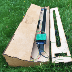
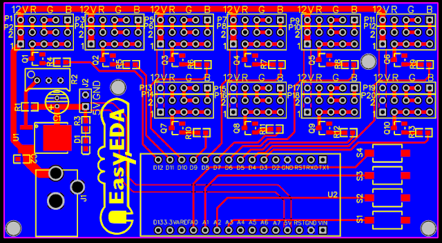
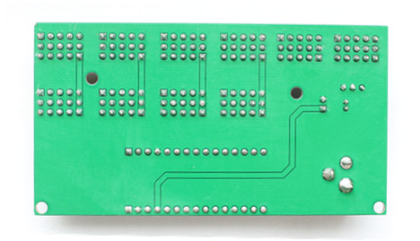
Known as the Screech Owl, the build is based around a custom shield designed to suit the Arduino Leonardo. The primary control interface is a Softpot 500 mm membrane potentiometer, layered up with a further thin film pressure sensor which provides aftertouch control. The Leonardo reads these sensors and synthesizes the appropriate frequencies in turn.

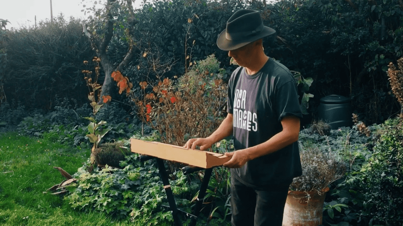
All the electronics is wrapped up inside a tidy laser-cut enclosure that roughly approximates the design of the original Eowave device. [Ben] noted the value of services like Fiverr and ChatGPT for helping him with the design, while he also enjoyed getting his first shield design professionally manufactured via JLCPCB.

It’s a tidy build, and in [Ben’s] capable hands, it sounds pretty good, too. We’ve seen some other great ribbon controlled synths before, too. Video after the break.

Minimal Mill: The Minamil

Having a few machine tools at one’s disposal is a luxury that not many of us are afforded, and often an expensive one at that. It is something that a large percentage of us may dream about, though, and with some commonly available tools and inexpensive electronics a few people have put together some very inexpensive CNC machines. The latest is the Minamil, which uses a rotary tool and straps it to an economical frame in order to get a functional CNC mill setup working.

This project boasts impressively low costs at around $15 per axis. Each axis uses readily available parts such as bearings and threaded rods that are readily installed in the mill, and for a cutting head the build is based on a Dremel-like rotary tool that has a similarly low price tag. Let’s not ignore the essentially free counterweight that is used.

For control, an Arduino with a CNC shield powers the three-axis device which is likely the bulk of the cost of this project. [Paul McClay] also points out that a lot of the material he needed for this build can be salvaged from things like old printers, so the $45 price tag is a ceiling, not a floor.

The Minamil has been demonstrated milling a wide variety of materials with excellent precision. Both acrylic and aluminum are able to be worked with this machine, but [Paul] also demonstrates it in its capacity to mill PCBs. It does have some limitations but for the price it seems that this mill can’t be beat, even compared to his previous CNC build which repurposed old CD drives.

The HackadayPrize2021 is Sponsored by:

From Printer to Vinyl Cutter

Some might look at a cheap inkjet printer and see a clunky device that costs more to replace the ink than to buy a new one. [Abhishek Verma] saw an old inkjet printer and instead saw a smooth gantry and feed mechanism, the perfect platform to build his own DIY vinyl cutter.

The printer was carefully disassembled. The feed mechanism was reworked to be driven by a stepper motor with some 3D printed adapter plates. A solenoid-based push/pull mechanism for the cutting blade was added with a 3D printed housing along with a relay module. An Arduino Uno takes in commands from a computer with the help of a CNC GRBL shield.

What we love about this build is the ingenuity and reuse of parts inside the old printer. For example, the old PCB was cut and connectors were re-used. From the outside, it’s hard to believe that HP didn’t manufacture this as a vinyl cutter.

If you don’t have a printer on hand, you can always use your CNC as a vinyl cutter. But if you don’t have a CNC, [Abhishek] shares all the STL files for his cutter as well as the schematic. Video after the break.

Send Old-Fashioned Pager Messages with New-Fashioned Hardware

In a world of always-connected devices and 24/7 access to email and various social media and messaging platforms, it’s sometimes a good idea to take a step away from the hustle and bustle for peace of mind. But not too big of a step. After all, we sometimes need some limited contact with other humans, so that’s what [EverestX] set out to do with his modern, pocket-sized communication device based on pager technology from days of yore.

The device uses the POCSAG communications protocol, a current standard for pager communications that allows for an SMS-like experience for those still who still need (or want) to use pagers. [EverestX] was able to adapt some preexisting code and port it to an Atmel 32u4 microcontroller. With a custom PCB, small battery, an antenna, and some incredibly refined soldering skills, he was able to put together this build with an incredibly small footprint, slightly larger than a bottle cap.

Once added to a custom case, [EverestX] has an excellent platform for sending pager messages to all of his friends and can avoid any dreaded voice conversations. Pager hacks have been a favorite around these parts for years, and are still a viable option for modern communications needs despite also being a nostalgic relic of decades past. As an added bonus, the 32u4 microcontroller has some interesting non-pager features that you might want to check out as well.

Thanks to [ch0l0man] for the tip!

Hack a Day 18 May 21:00

Simultaneous Soldering Station

Soldering irons are a personal tool. Some folks need them on the cool side, and some like it hot. Getting it right takes some practice and experience, but when you find a tip and temp that works, you stick with it. [Riccardo Pittini] landed somewhere in the middle with his open-source soldering station, Soldering RT1. When you start it up, it asks what temperature you want, and it heats up. Easy-peasy. When you are ready to get fancy, you can plug in a second iron, run off a car battery, record preset temperatures, limit your duty-cycle, and open a serial connection.

The controller has an Arduino bootloader on a 32u4 processor, so it looks like a ProMicro to your computer. The system works with the RT series of Weller tips, which have a comprehensive lineup. [Riccardo] also recreated SMD tweezers, and you can find everything at his Tindie store.

Soldering has a way of bringing out opinions from novices to masters. If we could interview our younger selves, we’d have a few nuggets of wisdom for those know-it-alls. If ergonomics are your priority, check out TS100 3D-printed cases, which is an excellent iron, in our opinion.

The HackadayPrize2020 is Sponsored by:

Make Your Own MIDI Controller With An Arduino

Engineers create something out of nothing, and no where is this more apparent than in the creation of customized computer hardware. To make a simple MIDI controller, you need knowledge of firmware design and computer architecture, you need knowledge of mechanical design, and you need to know electronic design. And then you need the actual working knowledge and experience to wield a tool, be it a hammer, laser cutter, or an IDE. [Mega Das] brought together all of these skill to build a MIDI controller. Sure, it’s for bleeps and bloops coming out of a speaker, but take a step back and realize just how awesome it is that any one person could imagine, then implement such a device.

The electronics for this build include a printed circuit board that serves to break out the connections on an Arduino nano to a dozen arcade push buttons, four slide pots, two rotary pots, and a handful of screw terminals to connect everything together. Mechanically, this is a laser-cut box engraved with some fancy graphics and sized perfectly to put everything inside.

Yes, we’ve seen a lot of MIDI controllers built around the Arduino over the years, but this one is in a class by itself. This is taking off-the-shelf parts and customizing them to exactly what you want, and a prodigious example of what is possible with DIY hardware creation. You can check out the build video below.

Save Some Steps with this Arduino Rapid Design Board

We’re all familiar with the wide variety of Arduino development boards available these days, and we see project after project wired up on a Nano or an Uno. Not that there’s anything wrong with that, of course, but there comes a point where some hobbyists want to move beyond plugging wires into header sockets and build the microcontroller right into their project. That’s when one generally learns that development boards do a lot more than break the microcontroller lines out to headers, and that rolling your own design means including all that supporting circuitry.

To make that transition easier, [Sean Hodgins] has come up with a simple Arduino-compatible module that can be soldered right to a PCB. Dubbed the “HCC Mod” for the plated half-circle castellations that allows for easy soldering, the module is based on the Atmel SAMD21 microcontroller. With 16 GPIO lines, six ADCs, an onboard 3.3 V regulator, and a reset button, the module has everything needed to get started — just design a PCB with the right pad layout, solder it on, and surround it with your circuitry. Programming is done in the familiar Arduino IDE so you can get up and running quickly. [Sean] has a Kickstarter going for the modules, but he’s also releasing it as open source so you’re free to solder up your own like he does in the video below.

It’s certainly not the first dev module that can be directly soldered to a PCB, but we like the design and can see how it would simplify designs. [Sean] as shown us a lot of builds before, like this army of neural net robots, so he’ll no doubt put these modules to good use.

EasyEDA RGB5050 LED Scroll Bar


Guest Post Disclaimer

This is a guest post by the EasyEDA team. I would like to thank EasyEDA for providing this tutorial for everyone to enjoy. All information within this post was provided by EasyEDA.


Description

None of us could deny the fact that we would love with to play with LED’s and lighting stuff. I love to play with LED’s and create attractive lighting effects. This project was a result of such an attempt where I created a stunning RGB light effect using the popular development platform Arduino Nano. Let’s see the circuit, code and instruction on building this project:


Image source: EasyEDA


Arduino Libraries and IDE

No libraries are required for this project. The Arduino IDE can be downloaded from the Arduino website. Here is the download link.

ARDUINO CODE:


Preparing the LED strips

Cut down the LED strips into 10 single pieces. Make sure you cut them into equal halves and make sure that only the copper conduction plate in the strip is cut. Making a wrong cut disrupts the electrical conductivity between the LED’s. After cutting down into separate strips, you will need to connect each strip using a Dupont wire connectors.

Image source: EasyEDA


Designing the Control Board

I have made a custom control board that incorporates an Arduino Nano. The control board is used to boost the incoming signal from Arduino and lights up the corresponding LED strips.


Image source: EasyEDA


Control Board Circuit diagram

I used a free Online circuit and PCB designing platform called EasyEDA to develop my control board. It is pretty easy to use especially because of the large library of parts to choose from. Once the design is complete, you have the option to order it through EasyEDA. They offers great prices on custom PCB manufacturing. I have added 10 connection points for 10 LED strips. Each RGB LED strip is controlled by one of the Arduino Nano digital pins.. Transistors Q1,Q2,Q3….Q10 act as a switch for these LED strips for controlling 12V strips via a 5V signal from the Arduino. And switches S1,S2..S4 were added to be able to select the effect on the strip. The schematic can be seen below:


Schematic

You can access the actual EasyEDA schematic by clicking on the image below:

Image source: EasyEDA


PCB Board Design

Here is the PCB board design for this project.
You can access the actual EasyEDA design by clicking on the image below.

Image source: EasyEDA


PCB Fabrication

After completing the PCB design, you can click on the Fabrication icon.

You will then have access to the PCB order page which will allow you to download your PCB Gerber files that can be sent to any manufacturer. However it is a lot easier (and cheaper) to order it directly from EasyEDA.
Here you can select:

  • the number of PCBs you want to order
  • the number of copper layers you need
  • the PCB thickness
  • copper weight
  • and even the PCB color
After you’ve selected all of the options, click “Save to Cart” and complete you order. You will then get your PCBs shipped a few days later.

Image source: EasyEDA


PCB final product

When I received the PCBs, I am quite impressed with the quality, they are pretty nice.

Image source: EasyEDA


PCB Build of Materials

Image source: EasyEDA


PCB connections

Connect the LED strips through the connection points in the board. Make sure that you connect these correctly (push the connectors all the way onto the pin), because the chances of a short increase significantly with the number of wires connected. Once all the connections are done all that left is to install your Arduino Nano (pre-programmed with the Arduino code above), and to power the PCB with a 12V power supply.


Image source: EasyEDA


Project Video


Concluding comments

Hope you like this RGB light effects project, do try it out and post your feedback below.
 
Disclaimer:
This is a guest blog post by the EasyEDA team. All information within this post was provided by EasyEDA.

ScottC 11 Sep 07:09

Laser PCB Exposer Built From CD-ROM Drives

[Neumi] has built a CNC Laser using CD-ROM drives as the X and Y motion platforms. The small 405nm laser can engrave light materials like wood and foam. The coolest use demonstrated in the video is exposing pre-coated photo-resist PCBs.

With $61 US Dollars (55 Euro) for the Arduino, stepper drivers, and a laser in the project, [Nuemi] got a pretty capable machine after adding a few parts from the junk bin. He wanted to avoid using existing software in order to learn the concepts behind a laser engraver. In the end, he has a working software package which can send raster scans to an Arduino mega. The mega then controls the sync between the stepper and laser firings. The code is available on GitHub.

The machine can do a 30x30mm PCB in 10 minutes. It’s not about to set a record, but it’s cool and not at all bad for the price. You can see the failed PCBs lined up in the video from the initial tuning, but the final one produced a board very equivalent to the toner transfer method. Video after the break.


Filed under: Arduino Hacks, cnc hacks
Hack a Day 15 Mar 06:00