Posts with «pcb» label

48 Solenoids Transform This 1960s Typewriter into a Computer Printer

Several years ago, Chris Gregg, a Tufts University lecturer and computer engineer, received a letter from his friend Erica. This wouldn’t be so unusual, except that it was typed on an actual typewriter, not a printer. Gregg is a fan of vintage typewriters, but, as with myself, makes many mistakes, […]

Read more on MAKE

The post 48 Solenoids Transform This 1960s Typewriter into a Computer Printer appeared first on Make: DIY Projects, How-Tos, Electronics, Crafts and Ideas for Makers.

Fritzing is out with a new release including Arduino Yún microcontroller!

Fritzing is an open-source hardware initiative that makes electronics accessible as a creative material for anyone. You can easily learn how to build a circuit for you project and also design your own PCB.

Last week, the Fritzing team announced the new release with a number of new parts, especially a number of popular microcontrollers, among which also Arduino Yún:

We have upgraded to their latest version Qt5, which brings stability and speed improvements (especially for Mac OS X users). This also enables us to port fritzing to Android, iOS, etc.

You can download Fritzing 0.9.0b at this link.


Arduino Blog 28 Jul 16:39

Handheld Game System Powered by Arduino

These days, it’s easy enough to play games on the go. If you have a smart phone, you are pretty much set. That doesn’t mean you can’t still have fun designing and building your own portable gaming system, though.

[randrews] did just that. He started out by purchasing a small memory LCD display from Adafruit. The screen he chose is low power as far as screens go, so it would be a good fit for this project. After testing the screen with a quick demo program, it was time to start designing the circuit board.

[randrews] used Eagle to design the circuit. He hand routed all of the traces to avoid any weird issues that the auto router can sometimes cause. He made an efficient use of the space on the board by mounting the screen over top of the ATMega chip and the other supporting components. The screen is designed to plug in and out of the socket, this way it can be removed to get to the chip. [randrews] needs to be able to reach the chip in order to reprogram it for different games.

Once the board design was finished, [randrews] used his Shapeoko CNC mill to cut it out of a copper clad board. He warns that you need to be careful doing this, since breathing fiberglass dust is detrimental to living a long and healthy life. Once the board was milled out, [randrews] used a small Dremel drill press to drill all of the holes.

The final piece of the puzzle was to figure out the power situation. [randrews] designed a second smaller PCB for this. The power board holds two 3V coin cell batteries. The Arduino expects 5V, so [randrews] had to use a voltage regulator. This power board also contains the power switch for the whole system.

The power board was milled and populated. Then it was time to do some measurements. [randrews] measured the current draw and calculates that he should be able to get around 15 hours of play time using the two 3V coin cell batteries. Not bad considering the size.

[via Reddit]


Filed under: Arduino Hacks
Hack a Day 23 Jun 06:00

Learn electronics with Chris Gammell and “Contextual Electronics”

Electrical engineer Chris Gammell has spent almost a year creating his new online electronics program called “Contextual Electronics“, and we’re excited to share this with our readers. You may have heard of Chris from his regular successful podcast with Dave Jones  – “The Amp Hour“.

Chris has the knowledge and expertise to take electronic ideas from simply that – an idea, right through to production. And by participating in his Contextual Electronics program you can learn the required skills to do this as well. Chris gives us a quick introduction in this video.

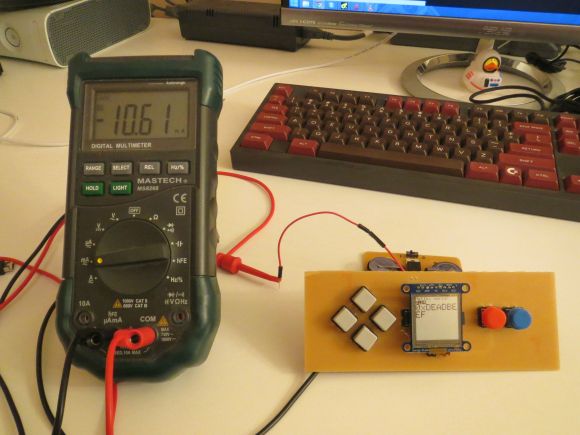
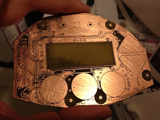
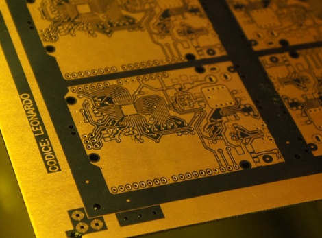
Contextual Electronics is a new program aimed at electronics enthusiasts who are ready to take their Arduino (or similar platform) skills to the next level. The first session of the course is an 8 week program that will teach you how to design a large, multi-function Arduino shield using KiCad, the open source CAD software.

It will also show you all of the design decisions that go into making the project. Here are some of the sub-circuits included in the 4-layer PCB design:

  • High level signals measurement using op-amps
  • Power supply output
  • Relay control
  • LED driver circuitry
  • Current source output

The course has a large community component, so you will be grouped with others learning at the same time, regardless of where you’re located in the world. The goal of the course and the community aspect is to make you more confident designing a project so you can go and design your own.

Future sessions of the course will also go over building, troubleshooting and coding for the shield described above. There is also a free short course that you can review to give you an idea of Chris’ methods and what the Contextual Electronics program will be like.

Additional courses will be developed using other popular development boards, including the Raspberry Pi and BeagleBone. For a more in-depth introduction, check out this video.

Frankly the program will help all of you who are ready to take your ideas and projects off the breadboard and into finished products, and with the guidance available with the program and the use of open-source tools you’ll be up and making things you can be proud of showing to friends or even potential employers. For more information about the program, and to sign up – visit the Contextual Electronics program website.

And if you enjoyed this article, or want to introduce someone else to the interesting world of Arduino – check out my book (now in a third printing!) “Arduino Workshop”.

Have fun and keep checking into tronixstuff.com. Why not follow things on twitterGoogle+, subscribe  for email updates or RSS using the links on the right-hand column, or join our forum – dedicated to the projects and related items on this website. Sign up – it’s free, helpful to each other –  and we can all learn something.

The post Learn electronics with Chris Gammell and “Contextual Electronics” appeared first on tronixstuff.

HackEDA hits Kickstarter, makes Arduino board design a drag-and-drop affair (video)

Writing code for an Arduino-friendly board is relatively easy; creating the board is the hard part, unless you live and breathe electrical engineering. If HackEDA has its way, however, the design process could be almost as easy as window shopping. Its new Kickstarter-backed project lets tinkerers choose from a list of parts and get a made-to-order board without knowing a lick about PCB assembly -- algorithms sort out the finer details. While the initial effort includes just 36 combos based around an Atmega328 processor, contributors who want tangible hardware can pay anything from $30 for a bare board through to $10,000 for the first stages of mass production. The truly committed will have to wait until December for the finished goods, but those willing to try HackEDA can use its existing web tool for free.

Filed under: Misc

Comments

Source: Kickstarter, HackEDA

Engadget 20 Jun 13:00

PCB production workshop means everyone gets an Arduino

Over at the LVL1 hackerspace in Lousiville, [Brad] is putting together a workshop on etching PCBs at home. [Brad] wanted all the participants to take home something cool, so he settled on an Arduino clone as the workshop’s project.

The clone [Brad] used is the Nanino, a single-sided board we’ve seen before. Unfortunately, there aren’t any CAD files for the Nanino and doing a toner transfer with the existing PDFs was a pain. This led [Brad] to redraw the Nanino in Diptrace and put the files up for everyone to grab.

In his workshop, [Brad] is going to be using a laser printer, hydrogen peroxide, and HCl. one of the most common setups for home etching. If you’re in the Louisville area, you can make your own Nanino with a home etching workshop on March 16th. Be careful, though: those LVL1 guys are pretty weird; they have a moat and are building a homicidal AI.


Filed under: tool hacks
Hack a Day 07 Feb 18:31
arduino  etching  lvl1  nanino  pcb  tool hacks  

2-Layered PCB with a Laser? Nah, Toner Transfer

I tried using the laser to remove some spray paint, and... I declare it a dud. Two major factors stymied this process for me for the moment:
  1. I didn't have the right spray paint (matte black) nor the right environment (dry and warm) for the paint I did have. What I did get to stick to the copper had a very uneven surface.
  2. The laser is... finicky. I can't tell if the layers were wildly inconsistent, if the paint behaved differently as it dried, or if maybe the laser had trouble, not liking the cold temperature or moist environment. I never can tell if it's about to give up.
Impatient as usual, I used my regular method: laser printer toner transfer. Determined to make a 2-sided board work, I spent a while aligning corner crop marks and pre-taping the paper with the toner before laminating it to the copper. The toner transfer was spectacular-- just perfect laminating it ten times (5 up, 5 down), but the top-bottom alignment, while close, may not be close enough. At this point it's etched and drilled, but there are still bridges and the misalignment will make assembly an adventure.

Looking at guides online, (especially the tutorial at An Engineer's Life which so many people are linking to today,) it does seem like most people use a photographic process and abandon toner transfer when they go for double-sided and SMD. Before going that route, I want to take toner transfer further though-- I've had such good results so far, the only issue is top-bottom alignment. The biggest sources of alignment error:
  1. Top-bottom alignment of printed out patterns. A light table, some magnets, and tape should do the trick-- I need to see the registration targets better.
  2. The laminator binds and jerks sometimes, which could distort the pattern slightly. It's hard to tell without sending through a test image, but it seems like time to take apart the laminator and see about modding it to separate the rollers a hair.
I'm happy with a slightly lower level of quality with toner transfer because it's a simpler process with fewer (and cheaper) expendables that can also transfer labeling to the top and bottom after etching.
Jeff's Arduino Blog 21 Dec 00:12
etch  pcb  toner transfer  

Laser for PCB Prototyping?

I've had a great time working on circuit designs in Eagle the last week or so-- after my surgery, my sciatic pain is mostly gone and I'm able to concentrate again! Still, I'm mostly confined to the neighborhood and can't lift or bend or exert myself for another few weeks, so I'm happily plugging away at a few projects, the main one of which is my latest coffee grinder timer.

The timer PCB's odd shape was dictated by enclosure's design, resulting in a 100mm x 74mm board. It needed to be double-sided, but traces were made wide and vias were kept to a minimum in the interest of home prototyping. I've had great success with toner transfer in the past, but not for 2-sided boards, and not for anything large.

A PCB-production process I've wondered about is using a laser engraver to remove an etch-resistant layer on copper before normal etching. The best and most successful example I've found is on Instructables: "Custom PCB Prototyping using a Laser Cutter," where the author uses flat black Krylon indoor/outdoor paint as the resist.

The example (at right) shows a single-sided board, but I'm primarily interested in using the process for excellent top-bottom registration. Before attempting the large board, I will first try some small pieces with test shapes, then I'll try a double-sided ATmega32u4 breakout board (my own design), then Grinder Timer 5. Stay tuned...
Jeff's Arduino Blog 17 Dec 22:38
eagle  homemade  laser  pcb  

DSS Circuits - bringing SMD to DIY

This is a cool site with some interesting PCB's including an I2C GPS Arduino sheild. The owner of the site, Wayne Truchsess has also written a great I2C library that I am using now.

Check out his open source tracking device that featured on Kickstarter here: http://www.kickstarter.com/projects/dsscircuits/open-source-tracking-device

read more

Let's Make Robots 18 Sep 06:52
arduino  gps  i2c  library  pcb  robot  shield  shops  smd  

Birth of an Arduino

Hey look, an Arduino without its clothes on. This one’s just started its journey to becoming the ubiquitous prototyping tool. The image is from [Bunnie's] recent tour of the fab house where Arduino boards are made.

As it says on every true Arduino board, they’re made in Italy. [Bunnie's] trip to the factory happened in Scarmagno, on the outskirts of Torino. The process starts with large sheets of FR4 copper clad material, usually about 1 by 1.5 meters in size. The first task is to send the sheets through a CNC drill. With all of the holes done it’s time for some etch resist; the image above is just after the resist has been applied. A robotic system takes over from here, running the panels through the chemicals which first etch away the copper, then remove the resist and plate the remaining traces. From there it’s off to another machine for solder mask and silk screen.

There are videos of each step available. But our favorite piece is the image at the end that shows a pallet with stacks of completed PCB panels which are headed off to be populated with components.

[via Reddit]


Filed under: arduino hacks
Hack a Day 15 Aug 12:01