-->-->-->-->

There are many CAD developed to assist the electronic designers during drawing of PCBs and schematics; often they are integrated in complete suite to project, simulate and realize a whole electronic system. Besides the many commercial versions, there are also free CADs available. Today we’d like to analyze one of the most diffused and known software: Eaglecad (eagle does not mean the powerful bird but it is the acronym of Easily Applicable Graphical Layout Editor) made by Cadsoft, actually at version 6.2.0. We have chosen this one because, as you know as an Arduino’s fan, the official pcbs and schematic files of the boards are developed and available free of charge to everybody in Eaglecad format; you can find also a lot of libraries and circuits made by famous DIY website (Sparkfun for first) available for free. Eaglecad is a professional software that have gained a lot of popularity due to the Arduino’s success. One of the most important difference between Eaglecad and its competitors is the availability of a version for every of the most common desktop OS: Windows, Linux, Mac. We have to specify that Eaglecad is not Free software but is a commercial one, which can be used in the free version (eaglecad light) only for evaluation purposes and by student but you can’t use the light version in any case when you earn or save money by using it. For further details about licenses and distributors have a look to the official Eaglecad website where you can find all the information you need. Remember that the light version has some limitations; anyway you can design circuit with a discrete complexity, as the one you can see at http://elmicro.com/en/kit12.html. The limitations are:
- pcb dimensions not bigger than 100×80 mm;
- no more than 2 layers;
- only 1 sheet for schematic.
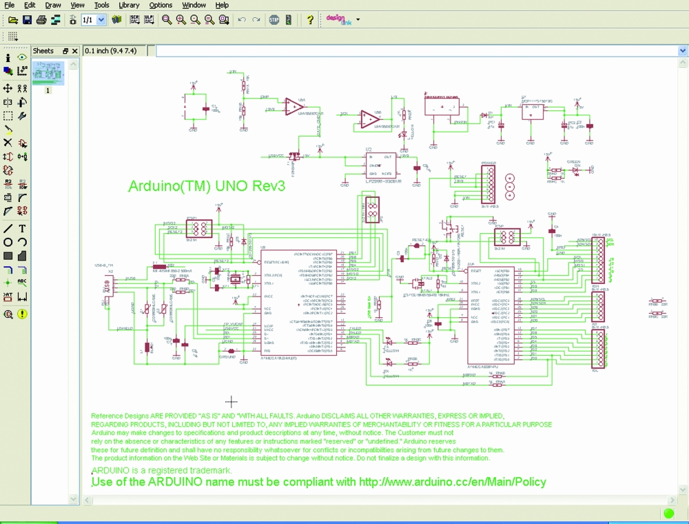
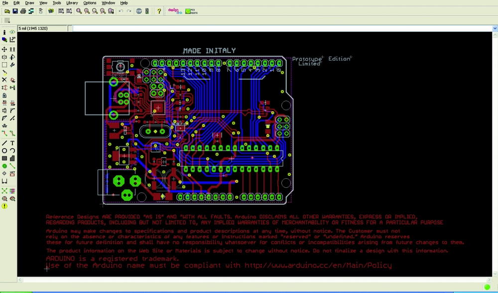
Now let’s have a look at the software itself starting from the GUI, which is made by three main units:
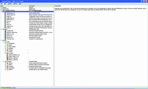
Control Panel
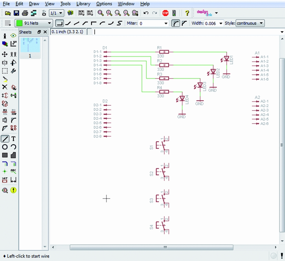
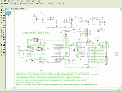
Schematic (you can see an Arduino’s UNO R3 board schematic screenshot)
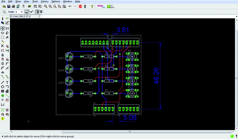
Board (the pcb editor) which can be seen “in action” which shows the pcb of the Arduino’s R3 board

For people used to the other similar cads, the interface is very closed to them and you’ll learn to use it easily; anyway to use the most powerful functions you need some practice.
The first thing you see at the CAD start up is the Control Panel, from which you can easily get access (for example) to the libraries, projects and examples; this is the software section where you can configure the main options like user’s folders, delay for the autosave option and the most important graphical parameters, all by getting access to the “OPTIONS” menu. The available documentation is pretty complete: you can access to the help function from the “help” menu available in both “Schematic” and “Pcb”. If you need further details you have to read the complete manual and the tutorial which are both available getting access to “Start” (on Windows), Programs-> Eagle Layout Editor 6.2.0.
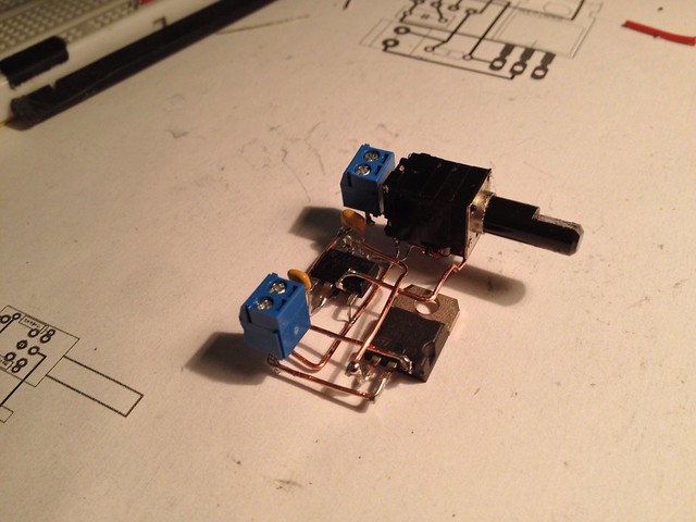
Let’s try to have practice with an example: we want to draw an Arduino’s shield made by 4 leds e da 4 switches, connected to 8 digital pins; it’s obvious due to the kind of circuit we are approaching to make, that this shield is only for training purposes. This pcb can be used to show the digital logic level of one or some pins, levels that could be changed by the four switches or to have a led alarm in case of an analog becomes higher or lower than some level.
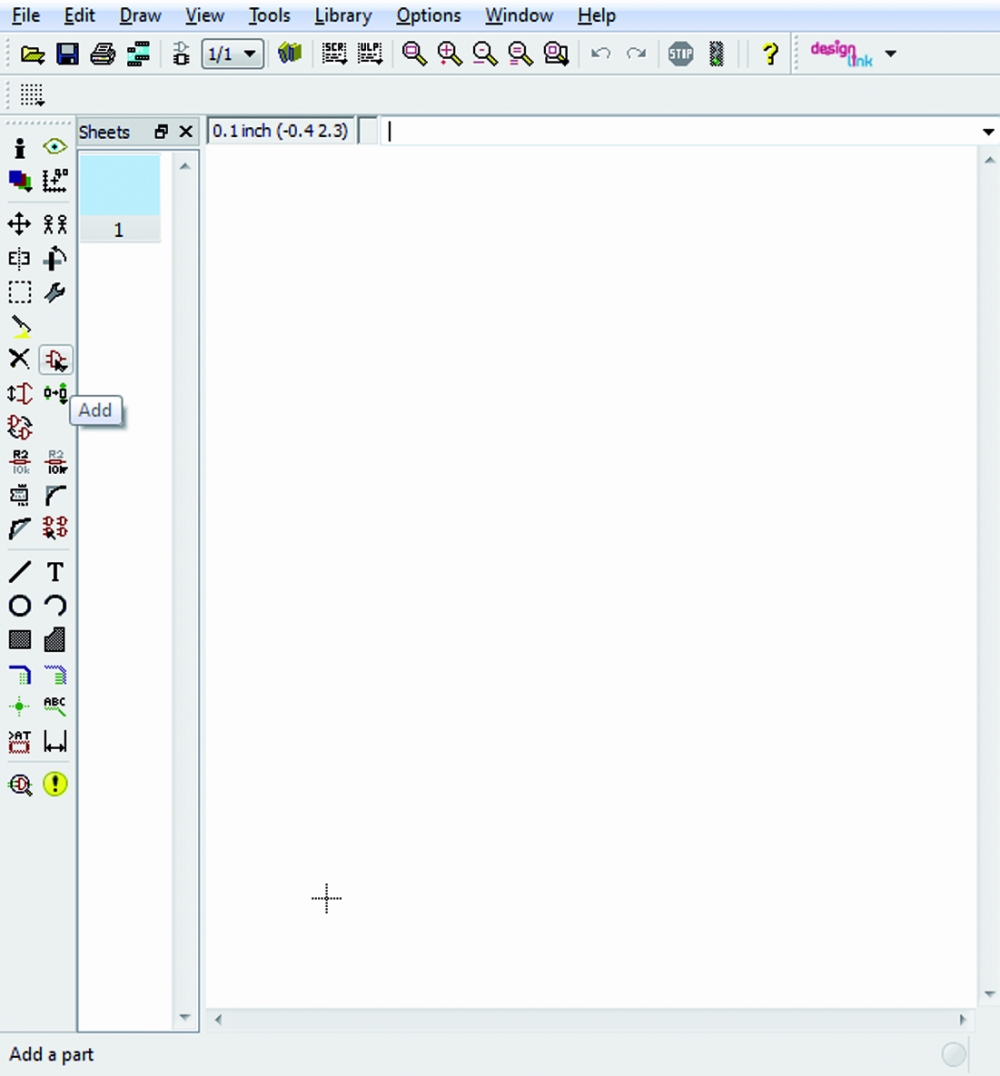
For first we have to draw the schematic so we select “FILE”, “NEW”, “SCHEMATIC” in this order: the Schematic window will open up. It is mainly made by two groups of icons: one on the top with the main commands like file management and zoom and another one on the left with the “drawing” icons.

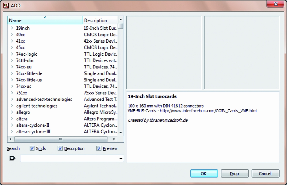
We can add the components by selecting the “AND” gate icon on the left hand side of the screen; when the cursor will be on it the word “Add” will pop up. Once selected, a list of libraries will be shown.
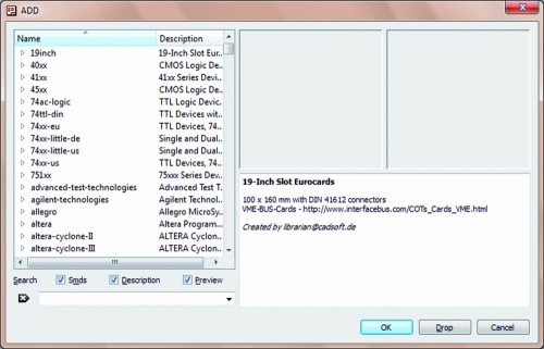
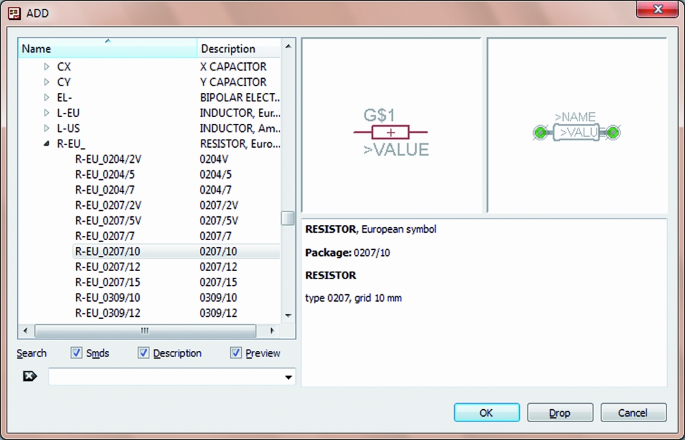
We can add other libraries like the Sparkfun one for example or we can also modify the ones which are provided by Eaglecad. Now select “Resistor”, “R-EU”: on the screen will appear a sub library where we can choose the kind of resistor we need (SMD,trough-hole) and its package.
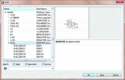
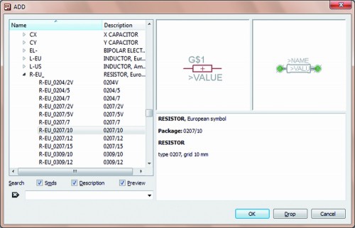
For our example we’d like to use trough hole components so we’ll choose “R-EU_02_07/10″ which is a 1/4W resistor horizontally mounted. Once a component has been chosen, on the right hand side of the window, Eaglecad shows the component symbol used in the schematic and beside the pcb pads of such component and the space required on the PCB. There is another window under the two we have seen before where there are details and notes that have been inserted during creation of the selected component.
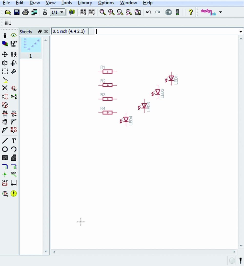
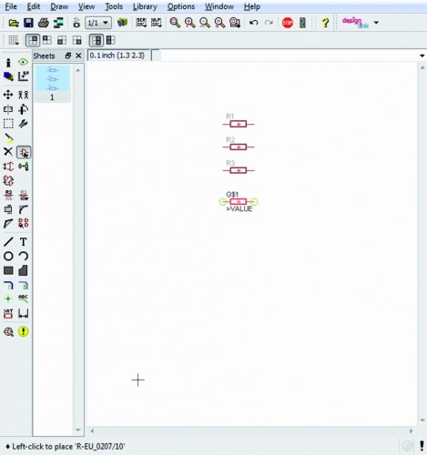
We need 4 of such components so we click on “OK”, move on the schematic drawing area and put the element where we want by clicking again. Eaglecad automatically names resistors in a progressive way.
When we have finished with these components, we have to select “ESC” on the keyboard: again the “ADD” window will open itself; now we select “LED5MM” in the “LED” sub-library which is contained into the “Led” library and we’ll draw four leds as done before.

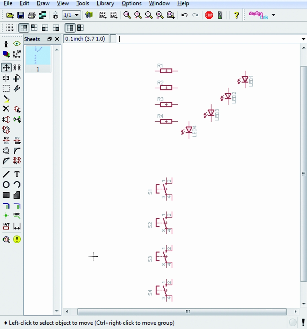
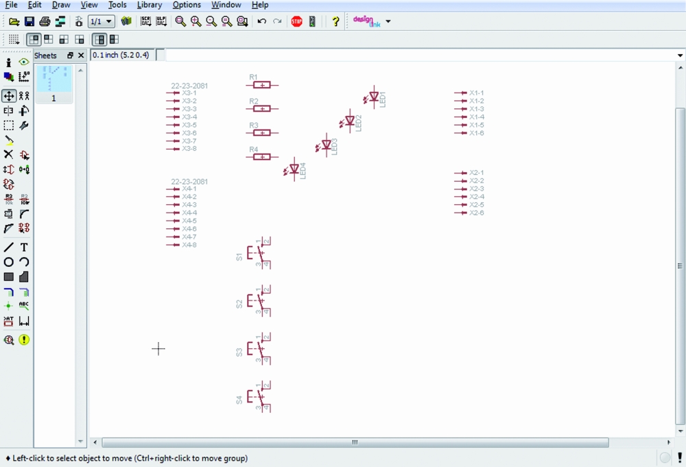
In the same way we can select the 4 switches “10-xx” available in the library “switch-omron”; these actions lead us to the situation shown here:

For the moment we can mainly focus our attention about the correct type of the connectors so we add, as explained before, two made by 6 contacts for the power supply section and the analog connections and other two made by 8 pins for digitals; the chosen connectors are the ones in the “con-molex” library, identified by “22-23-2061″ e “22-23-2081″. Push two times ESC to exit and so far we are in the conditions show:

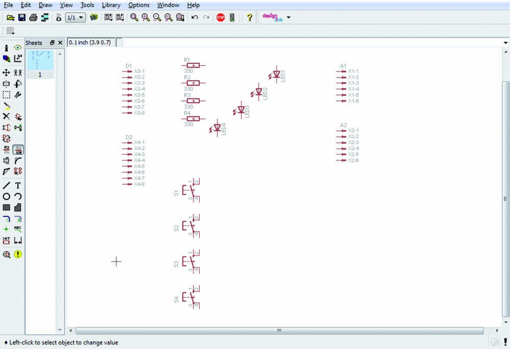
Now select the 4 resistors one at time, right-click and select “Value” in order to assign the desired value to each of them. Do the same with the 4 connectors, in order to change their value e.g. into A1, A2, D1, D2. A warning window with two choices will pop up: we’ll chose “Yes” and in the next window we’ll insert the required value. We’ll do the same for the next three strips.

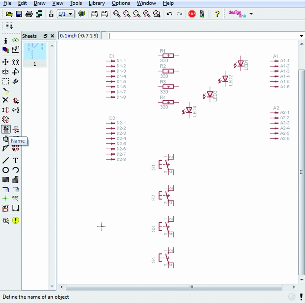
Now below every resistors there is the resistance value and also the four connectors have been renamed as required. It is also possible to rename every singol contact of every connector. Let’s do that, in order to avoid mistakes: select “name” in the left hand column and then put the mouse cursor on every contact to replace their name, e.g. “D1″, “D2″, “A1″, “A2″.

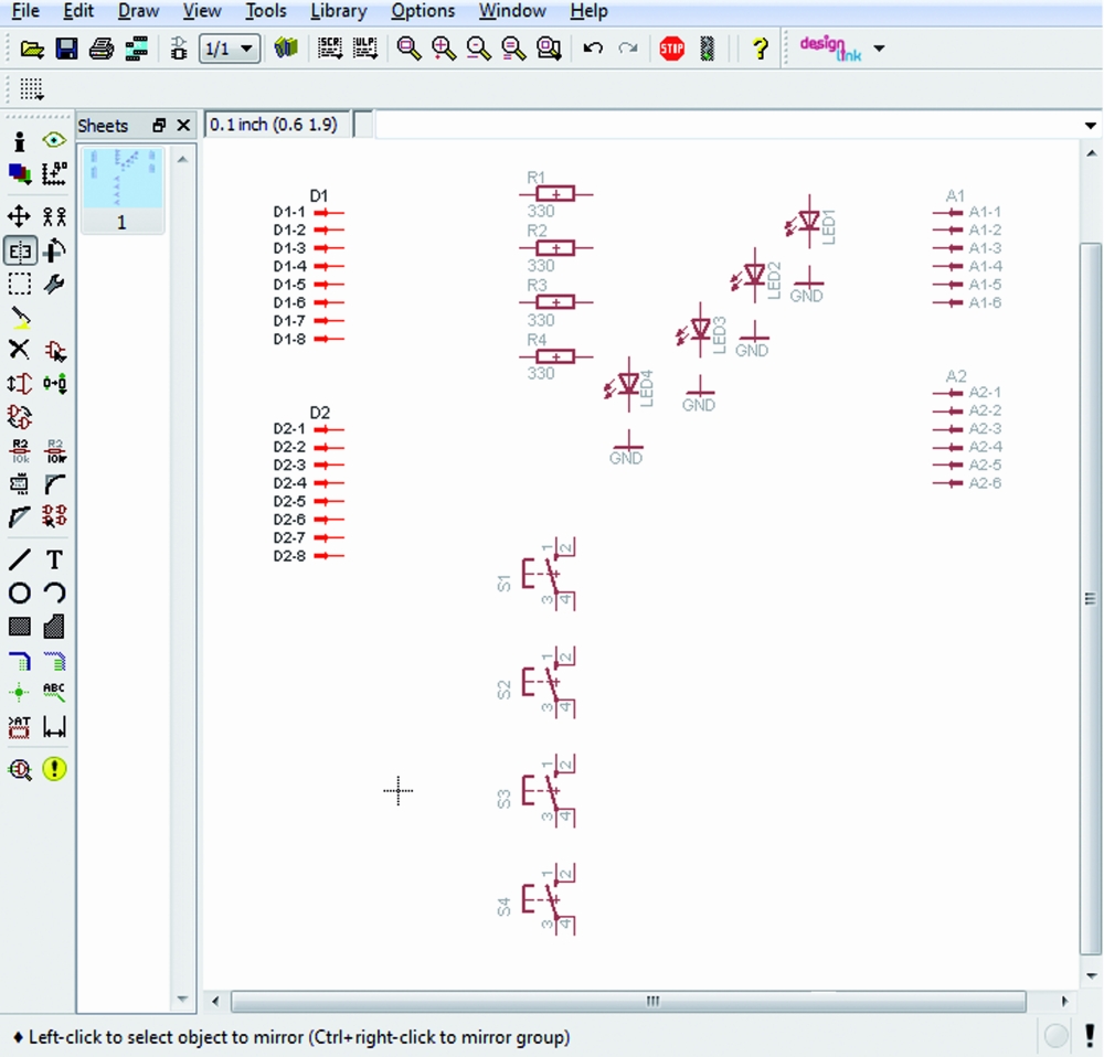
In this way it is easy to understand for every contact which is the related connector strip. Now insert the ground symbol and connect the LED cathodes to them (Eaglecad have available many kind of ground symbols: they are in the libraries “supply1″ and “supply2″). We’ll choose “GND” available in the “supply1″ library. Looking at the digital strips we can notice that they are in the “wrong” side of the schematic. To have a more easily access to the contact connections and to have a clear and readable schematic, we can use the”mirror” command to mirror the selected parts. Before apply this command, select the symbols of both connectors with the command “group” in order to reduce the number of required actions.

Select “Mirror” and then put the mouse pointer on the working area and select by left clicking first and then by right clicking “Mirror: Group”. Now it’ s time to draw connections. We can proceed in two ways: by selecting the commands “Draw” and “Wire” in sequence or by clicking with the left mouse switch on the related icon. To connect components put the cursor on the end of the symbol you want to connect, click with the left mouse switch and move the pointer on the terminal of the other components you have to connect to and click again.

To go to the next connection push ESC on the keyboard, put the mouse pointer where you want to draw the next wire and then left click again.
So far so good. We have focused our attention on LEDs, forgetting the switches. Never mind, we can insert, modify, delete, change the inserted parts in the schematic every time we need it; now we insert the missing components adding the required connections.
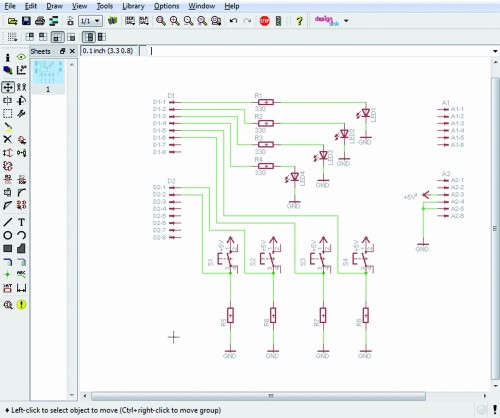
As you can see it’s easy to rotate and to move any part by using the related function in the “edit” menu or by selecting the desired icon in the left hand side column.
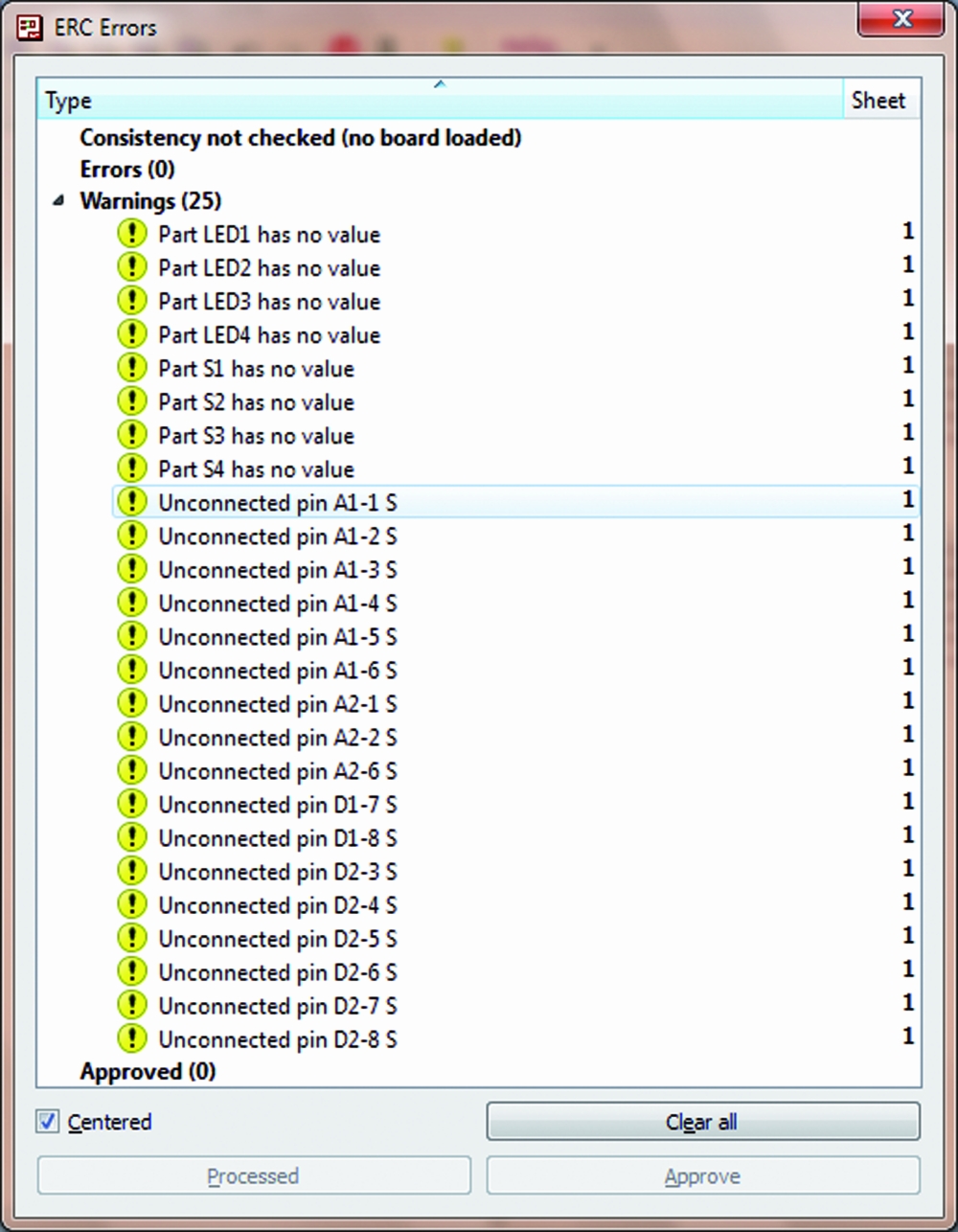
Once all the connections are done, select “Tool”, “Erc” to solve errors, if any, which will be shown in the “Erc errors” window where Eaglecad lists some issues: leds and switches have no value and the pins of the strips are not connected.
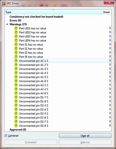
We don’t care about the missing values because they are not important in our schematic and we know that the unconnected pins are not used in our circuit. To confirm that, select “Approve” for all the requests and then with “Tools” and “”Errors” command we make sure that there are no further issues. Finally it’s time to draw the printed circuit board: left click on the “Board” icon which is the fifth starting from the left on the tool bar which is on the top of the working window.
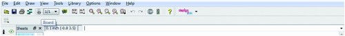
The system will ask us if we want to create the related file so we confirm “Yes” and then we’ll have on the screen the same picture as the one shown in figure:
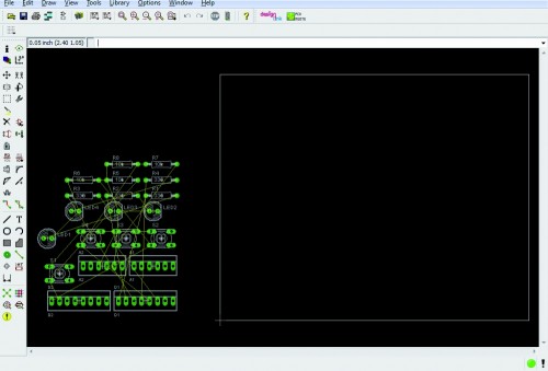
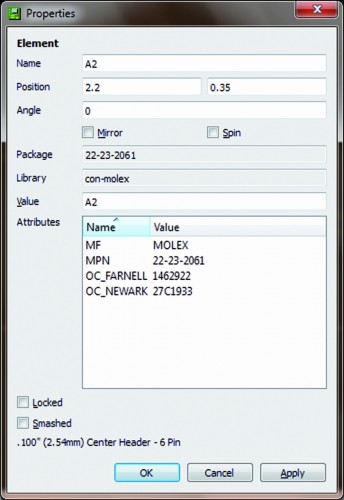
Using the command “Move” which can be selected by the icon with the four arrows in the left hand column, move the components where required. It’s better to start with the connectors due to they give the dimensions to the shield. Remember that the eight and the 6 pins connectors don’t have the same “step” on the board; in case of doubt check another shield, or you can refer to the pcb of the Uno which can be easily found on the Arduino’s website. The ones who have the R3 know that the strips have been redrawn to follow the increased needs of such system so the old connectors 8+8 and 6+6 have been replaced with 10+8 for digital pins and 8+6 for analog. In our example we have chosen to use the old connectors because they are compatible with all the Arduino version between 2009 and Uno and then because our shield was born for teaching reasons so it’s better to have it compatible also with the old pcb versions which are still used by many people. To insert the four connectors we can use the grid which help us; to change its resolution get access to “View”, “Grid” or “Properties” which is available by the “i” icon; in the last case we have also information about the absolute position in the working space.
Since the versions 6 of Eagleacad it is available another function which support us during drawing: “dimension” available through “Draw->Dimension”.
Wiring routing can be done automatically (autorouting function) or manually. In this short introduction we’ll use the hand routing in order to practice with Eaglecad. By selecting the “Route” icon it is possible to draw connections; the dimension, shape and width are visible on the top icon bar where is also possible to select the pcb side. The freeware version make possible to draw pcbs with only two sides, so we’ll find only “Top” and “Bottom”. In the same way you move components it is possible to define the printed circuit board dimensions; the white lines are the cutting boarder where the CNC will cut the pcb. Finally here a possible two sides pcb of our Arduino’s shield.

Special thanks to author Vincenzo Mendola.
-->-->-->-->-->-->
-->-->