Posts with «minimalduino» label

(F)Light Suit Major Components

The main components of the (F)Light suit:
(Updated 8/15/11)
Component(s)SourceStatus
LED stripsDealExtreme 22 strips with connectors, need sealing and velcro backing.
8-channel MOSFET Output BoardsDorkbotPDX board orderThree built and tested, work perfectly
Arm accelerometers Modern Device Left one on main board, right attached with 3-wire lead across shoulders
Black flight suit Amazon Needs velcro for LED strips
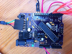
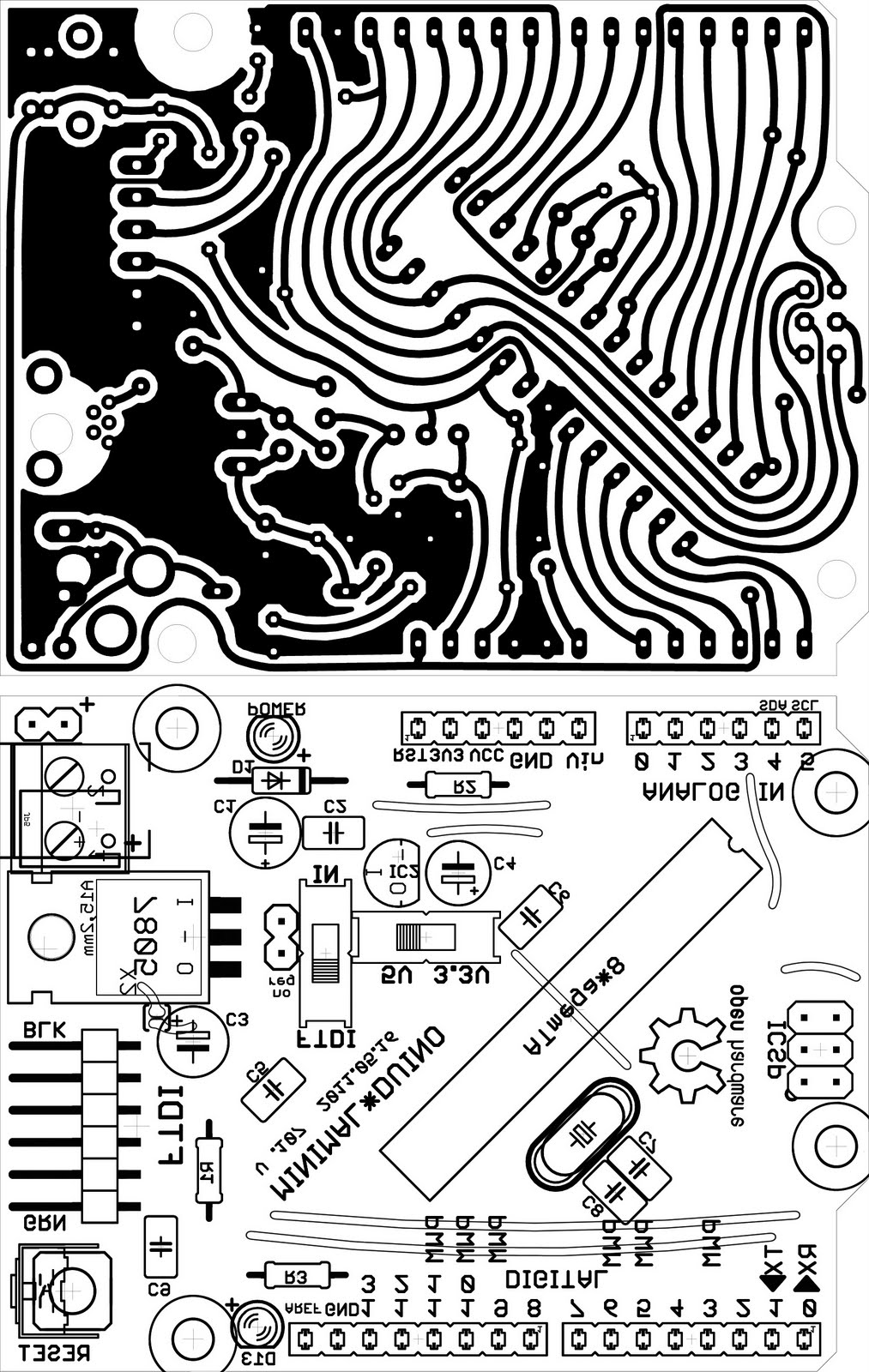
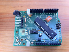
Arduino-compatible main board: Minimalduino 105 DorkbotPDX board order
Arduino interface board: Adafruit protoshield Adafruit Industries Done, ready for mounting and cable threading. Ports for MOSFET output boards, right accelerometer, remote control, audio sensor
Remote control homemade, various parts Needs laser-cut acrylic surround, rot 2 flaky
Batteries eBay 12V, 4800mAh Li-ion battery packs with barrel connectors, powering third MOSFET board.
Audio input: ZX-Sound board RobotShop.com Test, add light, change connector, paint, velcro back
Missing anything?

What is "Minimalduino"?

I started working on the "minimalduino" design as...
  1. a minimal hardware design for an Arduino-compatible board. At heart, it is very similar to the Dorkboard, but
  2. designed to match the form factor of the "official" Arduino boards so users can benefit from the many, many shield boards designed to fit on top. While (awesome) boards like EMSL's Diavolino are also low-cost and shield-friendly, I wanted to explore
  3. optional hardware configurations, with different power connector options (pin headers, JST connector, barrel jack, screw terminals, or mini USB jack), 5V and 3.3V power regulation and optional voltage switching and regulator bypassing, and options for crystal and caps or a resonator. I also wanted to have
  4. better shield-friendliness by placing LEDs (power and D13) and the reset switch (side switch or top switch) at the edges of the board, and lastly, I wanted the board to be
  5. single-sided, home-etchable with wide traces and minimal jumper wires. There is still work to be done to reduce jumpers, but it improves on the the S3V3 "Severino" board which doesn't match up size-wise (it's bigger), the standoff mounts don't match, and it uses a DB9 serial connector instead of the now widespread FTDI USB-serial breakout cable.

Minimalduino 105: Nice!

I built out one of the "V.105" boards I got a few weeks ago from the DorkbotPDX PCB order, and it works beautifully, almost identical to the version 107 I posted files of, with "5V/3.3V" voltage and "FTDI/IN" power selector switches. I mounted a mini USB socket and a 7805 regulator, in addition to the barrel jack for power in.

I've gone to whole number versioning btw, no need for "always under 1" versioning or major/minor versions, and if I need to go higher than 999 (huh?!), I can just use four digits.

Top and bottom labeling came out great, including the Open Hardware logo, though the letters mush together a little. Also, the "FTDI" header label didn't print at all, maybe there's a problem having two "FTDI" text labels.

One issue is that the drills for the main female headers are smaller than those on versions 89 and 97 boards, even though they use the same parts in EAGLE! I'll check the parts and maybe swap them out. That's a bummer-- I had to drill them all out to mount the headers, which ripped some of the pads off the fiberglass, but thankfully they stayed connected to the traces.

Minor edits for the next version:
  • Move the power input components to give electrolytic capacitors more room to accomodate shorter/fatter ones or taller ones mounted horizontally. As it is, the 100uF cap at the input is jammed between the .1uF cap and the barrel jack. [done]
  • Rotate LED's so they can be mounted horizontally for better side viewing when using a shield. [done]
  • Add heat sink polygon and vias under the 7805 tab.
  • Fix the Sparkfun mini USB through-hole part: its outline is on the bPlace layer, not tPlace where it belongs. Or just use a different part. [done]
  • Check female header drill diameters.
  • Add 2-pin header at the reset button to make it easier to add a remote panel-mounted reset button. [done]
  • Round the corners; looks nice on the Freetronics boards. Also check Uno outline and drills to make sure things are lined up right. [done]
I'm pretty happy with this for now though-- I have plenty of cheap, homemade, 5/3.3V-switchable Arduino-compatible boards to work with!

MinimalDuino 107 Pattern

After submitting the 105c version to the DorkbotPDX PCB order, I mentioned I'd make one at home, but the traces looked so thin on paper and I didn't like the routing of gnd to the crystal area, so I made a few changes to optimize it for toner transfer and home etching.

Here's a shared folder with the updated, v107 EAGLE files and a 600dpi jpeg for toner transfer. See the low res at right, or click for higher res; get the full res jpeg here.

Minimalduino v.105: Curvy Trace Fun

I've been trying out some Hope RFM12B radio modules-- very cool and inexpensive!-- which run off 3.3V. I've been using MinimalDuinos since they're 5V/3.3V switchable, and I got three version .97 boards made last year, with curvy traces, and they're coming in handy.

I have a few boards I'll need to get made over the next few months, so to warm back up with EAGLE, I polished up a straight (normal) trace version .105 board and set to curving it up. It took about an hour and a half, going around trace by trace in move mode, lots of command-clicking and dragging in the middle of trace segments to adjust their arcs. I submitted it to the DorkbotPDX PCB order before the deadline hit, and I can't wait to see what I get :) Design files and snapshots can be found here.

A key goal of the design is to have a good single-sided pattern for home etching, so I'll also make one by hand after fattening up as many traces as possible.

V.105 with straight traces:

Compare to V.105C, with curvy traces:

Minimal*duino V.96

I've done a little work on my "Minimalduino" Arduino-compatible board design lately:
  • Moved the fourth standoff mount hole to line up with the Uno's new fourth standoff hole (which they didn't make aligned to the one across the way!).
  • Fattened up the traces to make it more home-etcher-friendly: .016" and .024" traces, .018" min. separation.
  • Spread out the components, reduced the jumper count, and removed the I2C header.
  • Added pads for a mini USB jack, for power only. (I'm not sure about the grounded heat sink of a 7805 shorting to the 5V trace so I put in a solder bridge, but it's fine for making at home using real wires for the top layer jumpers.) So many options for powering this sucker!
Files can be found here.

Thinking about running this at 3.3V, I don't think it would work right for programming or for running with the FTDI cable attached.

Update: I had some v.97 boards made (DorkbotPDX order ftw!), same as .96 but with curvy traces and a few parts moved a little, here's one assembled: