

Tutorial – Using Long Range 315MHz RF Wireless Transceivers with Arduino
You can send data from one Arduino to another, or create a wireless remote-control system using inexpensive long-range 315MHz or 433MHz wireless data units.
Using this tutorial so you can quickly test and use your units, giving you the knowledge to build upon and make your own projects. So let’s get started!
Testing the modules
Our first guide is to simply test that data can be sent and received from one module to another. This is also an ideal setup for testing the radio range of the units in your area.
You will need:
- One set of 315MHz or 433MHz wireless data units
- Two Arduino Uno or similar boards and USB cables
- Two solderless breadboards
- Some male to male jumper wires
- One LED and a resistor of between 330 and 560 Ohms
- An external power supply for one Arduino. This can be an AC-DC wall wart, USB power bank, anything to power it without using the PC that has the receiving Arduino connected to it.
You also need to install the VirtualWire Arduino library. To do this:
- Download this .zip file into a temporary or your download directory.
- Open the Arduino IDE and select Sketch > Include Library > Add .zip Library…

- Navigate to the library .zip download and click “Open”:

After a few moments the library will be installed. You can check that this has completed by selecting Sketch > Include Library> then scroll down the long pop-up menu until you see “VirtualWire” as shown below:

Now – back to the hardware. Allocate one Arduino to be the transmitter, and one the receiver. Upload the following sketch to the transmitter board:
| // transmitter.ino | |
| // | |
| // Simple example of how to use VirtualWire to transmit messages | |
| // Implements a simplex (one-way) transmitter with an TX-C1 module | |
| // | |
| // See VirtualWire.h for detailed API docs | |
| // Author: Mike McCauley (mikem@airspayce.com) | |
| // Copyright (C) 2008 Mike McCauley | |
| // $Id: transmitter.pde,v 1.3 2009/03/30 00:07:24 mikem Exp $ | |
| #include <VirtualWire.h> | |
| const int led_pin = 11; | |
| const int transmit_pin = 12; | |
| const int receive_pin = 2; | |
| const int transmit_en_pin = 3; | |
| void setup() | |
| { | |
| // Initialise the IO and ISR | |
| vw_set_tx_pin(transmit_pin); | |
| vw_set_rx_pin(receive_pin); | |
| vw_set_ptt_pin(transmit_en_pin); | |
| vw_set_ptt_inverted(true); // Required for DR3100 | |
| vw_setup(2000); // Bits per sec | |
| pinMode(led_pin, OUTPUT); | |
| } | |
| byte count = 1; | |
| void loop() | |
| { | |
| char msg[7] = {'h','e','l','l','o',' ','#'}; | |
| msg[6] = count; | |
| digitalWrite(led_pin, HIGH); // Flash a light to show transmitting | |
| vw_send((uint8_t *)msg, 7); | |
| vw_wait_tx(); // Wait until the whole message is gone | |
| digitalWrite(led_pin, LOW); | |
| delay(1000); | |
| count = count + 1; | |
| } |
… and upload the following sketch to the receiver board:
| // receiver.ino | |
| // | |
| // Simple example of how to use VirtualWire to receive messages | |
| // Implements a simplex (one-way) receiver with an Rx-B1 module | |
| // | |
| // See VirtualWire.h for detailed API docs | |
| // Author: Mike McCauley (mikem@airspayce.com) | |
| // Copyright (C) 2008 Mike McCauley | |
| // $Id: receiver.pde,v 1.3 2009/03/30 00:07:24 mikem Exp $ | |
| #include <VirtualWire.h> | |
| const int led_pin = 2; | |
| const int transmit_pin = 12; | |
| const int receive_pin = 11; | |
| const int transmit_en_pin = 3; | |
| void setup() | |
| { | |
| delay(1000); | |
| Serial.begin(9600); | |
| Serial.println("setup"); | |
| // Initialise the IO and ISR | |
| vw_set_tx_pin(transmit_pin); | |
| vw_set_rx_pin(receive_pin); | |
| vw_set_ptt_pin(transmit_en_pin); | |
| vw_set_ptt_inverted(true); // Required for DR3100 | |
| vw_setup(2000); // Bits per sec | |
| vw_rx_start(); // Start the receiver PLL running | |
| pinMode(led_pin, OUTPUT); | |
| } | |
| void loop() | |
| { | |
| uint8_t buf[VW_MAX_MESSAGE_LEN]; | |
| uint8_t buflen = VW_MAX_MESSAGE_LEN; | |
| if (vw_get_message(buf, &buflen)) // Non-blocking | |
| { | |
| int i; | |
| digitalWrite(led_pin, HIGH); // Flash a light to show received good message | |
| // Message with a good checksum received, dump it. | |
| Serial.print("Got: "); | |
| for (i = 0; i < buflen; i++) | |
| { | |
| Serial.print(buf[i], HEX); | |
| Serial.print(' '); | |
| } | |
| Serial.println(); | |
| digitalWrite(led_pin, LOW); | |
| } | |
| } |
Wiring the modules is very easy, they are labelled well and drop straight into a solderless breadboard:

Now connect the transmitter module to your transmitter Arduino as such:
- Arduino GND to transmitter GND
- Arduino 5V to transmitter Vcc
- Arduino digital pin 12 to transmitter SIG:
Next, connect the receiver module to your transmitter Arduino as such:
- Arduino GND to receiver GND
- Arduino 5V to receiver Vcc
- Arduino digital pin 11 to receiver SIG
- LED and resistor in series between Arduino digital pin 2 and GND

Now that you’ve assembled both circuits, and uploaded the transmitter and receiver sketches to each board – it’s time to test.
Connect the transmitter board to power, and connect the receiver board to the PC. If not already open, run the Arduino IDE and open the serial monitor. You should notice two things:
- The LED on your receiver circuit should blink around once per second. When the LED blinks, this indicates the receiver circuit has successfully received a complete message from the transmitter
- The data sent from the transmitter is displayed in the serial monitor.
You can see this in action through the following video:
Our camera had trouble capturing the LED blink in some moments, but that’s ok.
You can also use this two Arduino setup to test the radio range – simply power the transmitter, and power the receiver circuit with a portable source of energy, such as a USB power bank – then walk away from the transmitter. The LED will stop blinking when you’re out of radio range.
You can increase the radio range by increasing the voltage to the transmitter unit – up to 12V DC.
Wireless Remote Control
Now to do something useful – create a wireless digital output control. Our transmitter will have two buttons, and our receiver will control two LEDs via digital outputs. Naturally this is an example, you can use this as a base to control other devices if required.
You will need:
- One set of 315MHz or 433MHz wireless data units
- Two Arduino Uno or similar boards and USB cables
- Two solderless breadboards
- Some male to male jumper wires
- Two LEDs and two resistors of between 330 and 560 Ohms
- Two tactile buttons and two 10k resistors OR two button breakouts
- An external power supply for one Arduino. This can be an AC-DC wall wart, USB power bank, anything to power it without using the PC that has the receiving Arduino connected to it.
We will use two tactile buttons and 10k Ohm pull-down resistors for input. If you’re not familiar with digital inputs and buttons, the building block for this is shown below.
The example diagram uses D12 as the input pin, however for this project your transmitter circuit will need two button circuits, using D8 and D7:

To save time we will use button breakout boards which combine the circuit into a neat unit ideal for prototyping:
Your receiver circuit is the same as the test circuit at the start of this tutorial, except that anothe LED circuit is added to digital pin 3.
Now for the sketches. Upload the following sketch to the transmitter (buttons) Arduino…
| // transmitter sketch | |
| // | |
| #include <VirtualWire.h> | |
| uint8_t buf[VW_MAX_MESSAGE_LEN]; | |
| uint8_t buflen = VW_MAX_MESSAGE_LEN; | |
| const char *on2 = "a"; | |
| const char *off2 = "b"; | |
| const char *on3 = "c"; | |
| const char *off3 = "d"; | |
| void setup() | |
| { | |
| vw_set_ptt_inverted(true); // Required for RF Link modules | |
| vw_setup(300); // set data speed | |
| vw_set_tx_pin(12); | |
| pinMode(8, INPUT); | |
| pinMode(7, INPUT); | |
| } | |
| void loop() | |
| { | |
| if (digitalRead(8)==HIGH) | |
| { | |
| vw_send((uint8_t *)on2, strlen(on2)); // send the data out to the world | |
| vw_wait_tx(); // wait a moment | |
| delay(200); | |
| } | |
| if (digitalRead(8)==LOW) | |
| { | |
| vw_send((uint8_t *)off2, strlen(off2)); | |
| vw_wait_tx(); | |
| delay(200); | |
| } | |
| if (digitalRead(7)==HIGH) | |
| { | |
| vw_send((uint8_t *)on3, strlen(on3)); | |
| vw_wait_tx(); | |
| delay(200); | |
| } | |
| if (digitalRead(7)==LOW) | |
| { | |
| vw_send((uint8_t *)off3, strlen(off3)); | |
| vw_wait_tx(); | |
| delay(200); | |
| } | |
| } |
… and upload the following sketch to the receiver (LEDs) Arduino:
| // receiver sketch | |
| // | |
| #include <VirtualWire.h> | |
| uint8_t buf[VW_MAX_MESSAGE_LEN]; | |
| uint8_t buflen = VW_MAX_MESSAGE_LEN; | |
| void setup() | |
| { | |
| vw_set_ptt_inverted(true); // Required for RF link modules | |
| vw_setup(300); | |
| vw_set_rx_pin(11); | |
| vw_rx_start(); | |
| pinMode(3, OUTPUT); | |
| pinMode(2, OUTPUT); | |
| } | |
| void loop() | |
| { | |
| if (vw_get_message(buf, &buflen)) | |
| { | |
| switch(buf[0]) | |
| { | |
| case 'a': | |
| digitalWrite(2, HIGH); | |
| break; | |
| case 'b': | |
| digitalWrite(2, LOW); | |
| break; | |
| case 'c': | |
| digitalWrite(3, HIGH); | |
| break; | |
| case 'd': | |
| digitalWrite(3, LOW); | |
| break; | |
| } | |
| } | |
| } |
You can see a quick demonstration in the following video:
So how did that work?
Review the transmitter sketch. A character is sent over the wireless link which determines the latest operation of the buttons – a, b, c or d (button one high/low, button two high/low).
Review the receiver sketch – on line 19 the switch-case function interrogates the incoming character from the wireless link and determines the action – in this case, controlling the digital outputs which have the two LEDs.
The response speed may seem a little slow – this will be affected by the data speed (300 bps). You can experiment with data speed and radio range (and voltage to the transmitter unit)
You can then alter this for your own means. You may not want to continuously send data as our example does, depending on your needs. As always, have fun and experiment.
Sending data wirelessly from one Arduino to another
Now we’ll show how to send some data in the form of an integer over our wireless link. This is ideal for sending the values of analog inputs, or other data that can be represented as an integer.
The hardware is the same as before – one Arduino transmitting and one Arduino receiving – with the receiver unit connected to a PC so we can use the Serial Monitor to display the received data.
Upload the following sketch to the transmitter Arduino…
| // data transmitter sketch// | |
| // | |
| #include <VirtualWire.h> | |
| // use onboard LED for status | |
| const int ledPin = 13; | |
| // we'll send the value of analog pin 1 | |
| const int Sensor1Pin = A1; | |
| int Sensor1Data; | |
| char Sensor1CharMsg[4]; | |
| void setup() | |
| { | |
| pinMode(ledPin, OUTPUT); | |
| pinMode(A1, INPUT); | |
| vw_setup(2000); // data speed in bps | |
| vw_set_tx_pin(12); //digital pin to data transmitter | |
| } | |
| void loop() | |
| { | |
| // get data from analog pin 1 | |
| Sensor1Data = analogRead(Sensor1Pin); | |
| // convert data from integer to character array | |
| itoa(Sensor1Data, Sensor1CharMsg, 10); | |
| digitalWrite(13, true); // onboard LED on to indicate transmitting | |
| vw_send((uint8_t *)Sensor1CharMsg, strlen(Sensor1CharMsg)); // send array | |
| vw_wait_tx(); // wait until data is sent | |
| digitalWrite(13, false); // onboard LED off to indicate finished transmitting | |
| delay(1000); // wait | |
| } |
… and the following sketch to the receiver Arduino.
| // data receiver sketch | |
| // | |
| #include <VirtualWire.h> | |
| // use onboard LED for status | |
| const int ledPin = 13; | |
| int Sensor1Data; | |
| // holds data from receiver | |
| char Sensor1CharMsg[4]; | |
| void setup() { | |
| Serial.begin(9600); | |
| pinMode(ledPin, OUTPUT); | |
| vw_set_ptt_inverted(true); | |
| vw_setup(2000); // data speed in bps | |
| vw_set_rx_pin(11); // receiver data pin to digital 11 | |
| vw_rx_start(); | |
| } | |
| void loop() { | |
| uint8_t buf[VW_MAX_MESSAGE_LEN]; | |
| uint8_t buflen = VW_MAX_MESSAGE_LEN; | |
| if (vw_get_message(buf, &buflen)) | |
| { | |
| int i; | |
| // LED on to indicate message coming in | |
| digitalWrite(13, true); | |
| for (i = 0; i < buflen; i++) | |
| { | |
| // fill array with data from receiver | |
| Sensor1CharMsg[i] = char(buf[i]); | |
| } | |
| // null terminate the char array, indicates the end of the data | |
| Sensor1CharMsg[buflen] = '\0'; | |
| // convert data in array to a usable integer | |
| Sensor1Data = atoi(Sensor1CharMsg); | |
| // send data to serial monitor | |
| Serial.print("tx analog pin 1 reads: "); | |
| Serial.println(Sensor1Data); | |
| // message reception finished, turn off onboard LED | |
| digitalWrite(13, false); | |
| } | |
| } |
Once operating and in radio range, the onboard LEDs will indicate successful transmission and reception of data. Open the serial monitor, and after a moment you will be presented with the data from analogue pin 1 of the transmitter Arduino – for example:

So how did that work?
Review the trasmitter sketch. We took a value from analog pin 1, and stored it into an integer variable on line 25. The VirtualWire library is geared to send data as characters so we convert the integer to a character array on line 28 – which is then sent as usual as shown in line 31.
Now review the receiver sketch. Nothing unusual, and the data from the receiver (in character form) is fed into the array at line 35. Once completed, we add “\0” to the end of the array to signify the end of the data.
The array is then converted back to an integer on line 42, then sent to the Serial Monitor.
So there you have it, we’ve sent integers across the airwaves. You can use your own “codes” with integers to mean all sorts of things and send them across. Ideal for temperature sensors, or anything really.
I hope you had fun experimenting with wireless units, or at least enjoyed reading about the possibilities. To keep up to date with new posts at tronixstuff.com, please subscribe to the mailing list in the box on the right, or follow us on x – @tronixstuff.
If you find this sort of thing interesting, please consider ordering one or more of my books from amazon:

 nRF24L01 boards and build yourself a copy of the remote control [saul] handily provides in
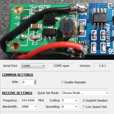 [Dave Akerman]’s interest in high-altitude projects means he is no stranger to long-range wireless communications, for which LoRa is amazingly useful. LoRa is a method of transmitting at relatively low data rates with low power over long distances.