Laser Harp Sets the Tone
In many ways, living here in the future is quite exiting. We have access to the world’s information instantaneously and can get plenty of exciting tools and hardware delivered to our homes in ways that people in the past with only a Sears catalog could only dream of. Lasers are of course among the exciting hardware available, which can be purchased with extremely high power levels. Provided the proper safety precautions are taken, that can lead to some interesting builds like this laser harp which uses a 3W laser for its strings.
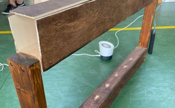
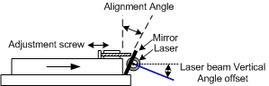
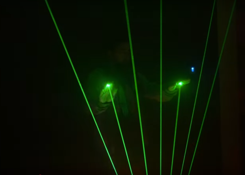
[Cybercraftics]’ musical instrument is using a single laser to generate seven harp strings, using a fast stepper motor to rotate a mirror to precise locations, generating the effect via persistence of vision. Although he originally planned to use one Arduino for this project, the precise timing needed to keep the strings in the right place was getting corrupted by adding MIDI and the other musical parts to the project, so he split those out to a second Arduino.
Although his first prototype worked, he did have to experiment with the sensors used to detect his hand position on the instrument quite a bit before getting good results. This is where the higher power laser came into play, as the lower-powered ones weren’t quite bright enough. He also uses a pair of white gloves which help illuminate a blocked laser. With most of the issues ironed out, [Cybercraftics] notes that there’s room for improvement but still has a working instrument that seems like a blast to play. If you’re still stuck in the past without easy access to lasers, though, it’s worth noting that there are plenty of other ways to build futuristic instruments as well.