Posts with «lidar» label

Machine Learning Robot Runs Arduino Uno

When we think about machine learning, our minds often jump to datacenters full of sweating, overheating GPUs. However, lighter-weight hardware can also be used to these ends, as demonstrated by [Nikodem Bartnik] and his latest robot.

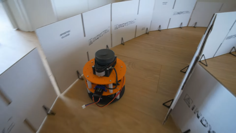
The robot is charged with autonomously navigating a simple racetrack delineated by cardboard barriers. The robot is based on a two-wheeled design with tank-style steering. Controlled by an Arduino Uno, the robot uses a Slamtec RPLIDAR sensor to help map out its surroundings. The microcontroller is also armed with a Bluetooth link and an SD card for storage.

The robot was first driven around the racetrack multiple times under manual control, all the while collecting LIDAR data. This data was combined with control inputs to help create a data set that could be used to train a machine learning model. Feature selection techniques were used to refine down the data points collected to those most relevant to completing the driving task. [Nikodem] explains how the model was created and then refined to drive the robot by itself in a variety of race track designs.

It’s a great primer on machine learning techniques applied to a small embedded platform.

DolphinView headset lets you see the world like Flipper!

Dolphins are not only amazing swimmers and extremely intelligent, but can also observe their surroundings using echolocation. While extremely useful in murky water, Andrew Thaler decided to make a device that would enable him to him observe his (normally dry) surroundings with a similar distance-indicating audio setup.

While he first considered using an ultrasonic sensor, he eventually settled on LiDAR for its increased range, and uses an Arduino to translate distance into a series of audio clicks. Sound is transferred to Thaler through bone conduction speakers, mimicking the way dolphins hear without external ears. 

He notes that while using the “DolphinView” headset is initially disorienting, he was eventually able correlate his surroundings with the system’s audio feedback. Arduino code and parts list is available on GitHub, and the mechanical frame design can be found on Thingiverse if you’d like to build your own!

Arduino Blog 26 Jul 15:31

Lunar landing conspiracy put to rest(?) with LIDAR

On July 20th, 1969 man first set foot on the moon with the Apollo 11 mission, or so they say. If it was faked, or so the theory goes, one would think that there were a few details that don’t quite add up. One such theory is that the hatch on the lunar module isn’t actually large enough to allow a fully-suited up astronaut to enter and exit the module.

Rather than make assumptions, astrophotographer and hacker “AstronomyLive” took matters into his own hands and used a homemade LIDAR unit to measure the hatch of Lunar Module #9 at the Kennedy Space Center, as well as an Apollo spacesuit.

The Arduino-powered device aims the laser, and transmits this information to a tablet that also provides a convenient user interface. This data was then arranged as a point cloud, proving that… You can take a guess, or watch the video below to see his conclusion!

I used the Garmin LIDAR-Lite V3 along with a couple of metal geared servo motors to build a simple pan/tilt scanner, which pairs via Bluetooth to an Android app I built using MIT App Inventor 2 to control and receive data from the Arduino. It’s simple but effective. Although every tutorial I read suggested I couldn’t safely pull the voltage off the board for the motors, but I found that the vin pin gave me no problems, as long as I used a 5V 1.5A linear voltage regulator between the pin and the motors. I supplied 9V using AA batteries to the power jack on the Arduino. In the future I may upgrade the scanner by adding a small camera to grab RGB data for each point as it samples, and ideally I would change the whole thing to use a stepper motor for continuous spinning and scanning to generate a denser cloud.

Debunking Moon Landing Denial with an Arduino and Science

It’s sad that nearly half a century after the achievements of the Apollo program we’re still arguing with a certain subset of people who insist it never happened. Poring through the historical record looking for evidence that proves the missions couldn’t possibly have occurred has become a sad little cottage industry, and debunking the deniers is a distasteful but necessary ongoing effort.

One particularly desperate denier theory holds that fully spacesuited astronauts could never have exited the tiny hatch of the Lunar Excursion Module (LEM). [AstronomyLive] fought back at this tendentious claim in a clever way — with a DIY LIDAR scanner to measure Apollo artifacts in museums. The hardware is straightforward, with a Garmin LIDAR-Lite V3 scanner mounted on a couple of servos to make a quick pan-tilt head. The rig has a decidedly compliant look to it, with the sensor flopping around a bit as the servos move. But for the purpose, it seems perfectly fine.

[AstronomyLive] took the scanner to two separate museum exhibits, one to scan a LEM hatch and one to scan the suit Gene Cernan, the last man to stand on the Moon so far, wore while training for Apollo 17. With the LEM flying from the rafters, the scanner was somewhat stretching its abilities, so the point clouds he captured were a little on the low-res side. But in the end, a virtual Cernan was able to transition through the virtual LEM hatch, as expected.

Sadly, such evidence will only ever be convincing to those who need no convincing; the willfully ignorant will always find ways to justify their position. So let’s just celebrate the achievements of Apollo.

Hackaday Prize Entry: Cheap, Open LiDAR

[adam] is a caver, meaning that he likes to explore caves and map their inner structure. This is still commonly done using traditional tools, such as notebooks (the paper ones), tape measure, compasses, and inclinometers. [adam] wanted to upgrade his equipment, but found that industrial LiDAR 3D scanners are quite expensive. His Hackaday Prize entry, the Open LIDAR, is an affordable alternative to the expensive industrial 3D scanning solutions out there.

The 3D scan of a small cave near Louisville from [caver.adam’s] Sketchfab repository
LiDAR — Light Detection And Ranging —  is the technology that senses the distance between a sensor and an object by reflectively measuring the time of flight of a light beam between the two. By acquiring a two-dimensional array of multiple distance readings, this can be used for 3D scanning. Looking at how the industrial LiDAR scanners capture the environment using fast spinning mirrors, [adam] realized that he could basically achieve the same by using a cheap laser range finder strapped to a pan and tilt gimbal.

The gimbal he designed for this task uses stepper motors to aim an SF30-B laser rangefinder. An Arduino controls the movement and lets the eye of the sensor scan an object or an entire environment. By sampling the distance readings returned by the sensor, a point cloud is created which then can be converted into a 3D model. [adam] plans to drive the stepper motors in microstepping mode to increase the resolution of his scanner. We’re looking forwards to see the first renderings of 3D cave maps captured with the Open LIDAR.

The HackadayPrize2016 is Sponsored by:

Filed under: The Hackaday Prize

Pew Pew! An Arduino Based Laser Rangefinder


Lasers are some of the coolest devices around. We can use them to cut things, create laser light shows, and also as a rangefinder.[Ignas] wrote in to tell us about [Berryjam's] AMAZING write-up on creating an Arduino based laser rangefinder. This post is definitely worth reading.

Inspired by a Arduino based LIDAR system, [Berryjam] decided that he wanted to successfully use an affordable Open Source Laser RangeFinder (OSLRF-01) from LightWare. The article starts off by going over the basics of how to measure distance with a laser based system. You measure the time between an outgoing laser pulse and the reflected return pulse; this time directly relates to the distance of the object. Sounds simple? In practice, it is not as simple as it may seem. [Berryjam] has done a great job doing some real world testing of this device, with nice plots to top it all off. After fiddling with the threshold and some other aspects of the code, the resulting accuracy is quite good.

Recently, we have seen more projects utilizing lasers for range-finding, including LIDAR projects. It is very exciting to see such high-end sensors making their way into the maker/hacker realm. If you have a related laser project, be sure to let us know!


Filed under: laser hacks

Success! OSLRF (LIDAR) successfully Scanning and providing accurate results.


I've been working on getting the OSLRF01 prov

read more

Let's Make Robots 10 Mar 12:49
arduino  lidar  oslrf01