Posts with «rangefinder» label

Ultrasonic Sonar Detects Hidden Objects

While early scientists and inventors famously underestimated the value of radar, through the lens of history we can see how useful it became. Even though radar uses electromagnetic waves to detect objects, the same principle has been used with other propagating waves, most often sound waves. While a well-known use of this is sonar, ultrasonic sensors can also be put to use to make a radar-like system.

This ultrasonic radar project is from [mircemk] who uses a small ultrasonic distance sensor attached to a rotating platform. A motor rotates it around a 180-degree field-of-view and an Arduino takes and records measurements during its trip. It interfaces with an application running on a computer which shows the data in real-time and maps out the location of all of the objects around the sensor. With some upgrades to the code, [mircemk] is also able to extrapolate objects hidden behind other objects as well.

While the ultrasonic sensor used in this project has a range of about a meter, there’s no reason that this principle couldn’t be used for other range-finding devices to extend its working distance. The project is similar to others we’ve seen occasionally before, but the upgrade to the software to allow it to “see” around solid objects is an equally solid upgrade.

Measuring the Time is a Breeze With This Air Flow Clock

If you’ve ever had surgery, and you’re over a certain age, chances are good you’re familiar with the dreaded incentive spirometer. It’s a little plastic device with one or more columns, each of which has a plastic ball in it. The idea is to blow into the thing to float the balls, to endure that your lungs stay in good shape and reduce the chance of pneumonia. This unique air-powered clock reminds us a little of that device, without all the pain.

Like a spirometer, [Nir Tasher]’s clock has three calibrated tubes, each big enough to hold a foam ball loosely. At the bottom of each tube is a blower whose motor is under PWM control. A laser rangefinder sits below each ball and measures its height; the measurement is used by a PID loop to control the speed of each fan and thus the height of each ball. The video below shows that the balls are actually pretty steady, making the clock easy to read. It doesn’t, however, reveal what the clock sounds like; we’re going to go out on a limb here and guess that it’s pretty noisy. Still, we think it’s a fantastic way to keep time, and unique in the extreme.

[Nir]’s Air Flow clock is an early entry in the 2020 Hackaday Prize, the greatest hardware design contest on Earth. Everyone should enter something, or at least check out the cool things people are coming up with. It’s still early in the process, but there are so many neat projects already. What are you waiting for?

The HackadayPrize2020 is Sponsored by:

Pew Pew! An Arduino Based Laser Rangefinder


Lasers are some of the coolest devices around. We can use them to cut things, create laser light shows, and also as a rangefinder.[Ignas] wrote in to tell us about [Berryjam's] AMAZING write-up on creating an Arduino based laser rangefinder. This post is definitely worth reading.

Inspired by a Arduino based LIDAR system, [Berryjam] decided that he wanted to successfully use an affordable Open Source Laser RangeFinder (OSLRF-01) from LightWare. The article starts off by going over the basics of how to measure distance with a laser based system. You measure the time between an outgoing laser pulse and the reflected return pulse; this time directly relates to the distance of the object. Sounds simple? In practice, it is not as simple as it may seem. [Berryjam] has done a great job doing some real world testing of this device, with nice plots to top it all off. After fiddling with the threshold and some other aspects of the code, the resulting accuracy is quite good.

Recently, we have seen more projects utilizing lasers for range-finding, including LIDAR projects. It is very exciting to see such high-end sensors making their way into the maker/hacker realm. If you have a related laser project, be sure to let us know!


Filed under: laser hacks

Joystick operated security cam will overlook the moat

What good is a moat if nobody is guarding it? We suppose that depends on what beasties lurk beneath the surface of the water, but that’s neither here nor there. The members of LVL1 continue their quest to outdo each other in augmenting the building’s automated features. The latest offering is this security camera which is operated with an analog thumb stick.

These are the people who are building a moat (which the city things is a reflecting pool) in front of their main entrance. Now they will be able to see and sense if anyone is trying to get across the watery hazard. The hack marries an ultrasonic rangefinder and camera module with a pair of servo motors. The brackets for the motors allow a full range of motion, and the signal is translated by an Arduino and Video Experimenter shield to put out a composite video signal. That’s not going to make streaming all that easy, but we’re sure that is just one more hack away.


Filed under: Hackerspaces, video hacks

Physics Lab 3

The Physics Lab 2 post and Physics class progress described some experiments we were going to do this week with the ultrasonic range finder(s).

What we actually did, after spending a fair amount of time discussing the schedule for the year and expectations (one of the students has not started yet, because of the amount of time he was putting into his Stanford essays—I hope he gets in after all the effort he has expended, was to drop balls and try measuring the drop with both the Maxbotix sensor and a video camera.

We tried both a ping-pong ball and a slightly larger plastic ball.  With both of them the Maxbotix sensor only detected them intermittently, and we go no useful data from the rangefinder.

The HD video from the camera was more usable, but I was not aware that Tracker could use MTS (AVCHD format) files, since it greyed them out. I wasted a lot of time converting the movies to .mov format using iMovie, a piece of software that I have come to hate for its slowness, inefficient use of disk, rigid insistence on a specific directory structure, and generally unfriendly and unintuitive user interface. I’ve gone so far as to buy Premiere Elements, with the hope that it is not so awful (but I’ve not tried to use it yet, so it might be just as bad).

It turned out that my son had not installed the Tracker software on the desktop machine, so we had to get out my laptop and try analyzing the frames there.  I remembered how to calibrate and get the autotracking set up, but I forgot how to specify the beginning and ending frame (I eventually figured it out, but only after some false starts).  The data was pretty clean, though autotracking did lose the ball at one point because of some really stupid projections about where it ought to be.  Redoing the autotracking fixed that problem.  The errors in the tracking due to motion blur were not noticeable in the position plot, made small wiggles in the velocity plot, and made huge wiggles in the acceleration plot.  We did get a chance to talk about how a ±1mm error in position results in a ±3 cm/sec error in velocity and a ±90 cm/sec2 error in acceleration, when using 30 frames per second.

I tried redoing the autotracking using the AVCHD format directly from the camera, but it turns out that AVCHD uses interlaced images, so one gets two pictures of the ball in each frame. When the ball is motionless, this makes a nice circle, but when the ball is moving fast, you get two striped circles that may overlap. Tracker has trouble handling the interlacing, though a really clever algorithm could take advantage of it to get effectively double the frame rate when tracking large objects moving with reasonably constant acceleration.

Bottom line was that neither the ultrasonic rangefinder nor Tracker resulted in fast, painless measurement. We’ll have to try again next week, perhaps with bigger targets for the rangefinder. I initially thought that brighter light for the video would reduce motion blur by reducing shutter time, but it seems that the motion blur is due to interlacing, not to a slow shutter, so changing the lighting won’t help. Algorithmic changes to Tracker would be needed.

What to do in next week’s lab

  1. Analyze the balldrop clips (in .mov format). For calibration, the distance we measured between the top and bottom stile of the file cabinet was 112cm. Since the ball was a few cm in front of the file cabinet, there may be some perspective error in using that measurement to calibrate the drop. Get Tracker to give you position, velocity, and acceleration plots. Use the fluctuation in the acceleration estimates to estimate the errors in the velocity and position measurements.
  2. Write a Vpython program that simulates the motion of the falling ball including the initial pause before dropping, but not including the bounces.

Other homework

  • Read Chapter 3.
  • Work problems 3.P.36, 3.P.40, 3.P.43, 3.P.46, 3.P.52, 3.P.65, 3.P.72.
  • Do computational problem 3.P.76. Note that the computational problems for Chapter 3 are not independent of each other, and you should read all the preceding problems to get hints for this problem.

Tagged: AP physics, Arduino, high school, physics, rangefinder, Tracker, ultrasonic sensor, VPython

Physics class progress

The physics class that I’m doing with my son and another home schooler is going a bit slowly.  The other student couldn’t make it again this week (Stanford early admission deadlines, and he needed the time to polish his application essays).

My son and I compared answers to the Chapter 2 problems I’d assigned (see Physics Lab 2).  We’d each made some careless errors (in one, I’d neglected to take a square root, though I’d written the right formula, in another, I’d forgotten to add the sideways movement during acceleration, in a third, my son had forgotten to divide by 2 at one point).  In short, neither of us were doing “A” work—we knew what we were doing, but were being inexcusably sloppy in the computations (me more so than my son). I’ll have to do better on Chapter 3.

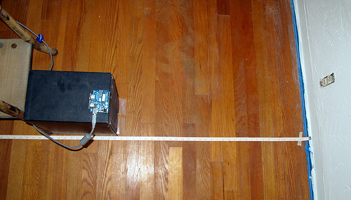
I think that I won’t assign any exercises in Chapter 3 this week, to give the other student a chance to catch up.  Instead, I’ll ask my son to finish the data-acquisition code for the ultrasonic rangefinder.  I wrote some simple code running on the Arduino for gathering the data, and he was going to write a Python program (using PySerial) to record the data and output it in a format suitable for plotting with gnuplot.

Our goal is to finish at least the Newtonian mechanics (Chapters 1–13 of Matter and Interactions) before the AP Physics C exam (afternoon of 14 May 2011), which gives us time for a little over 2 weeks per chapter.  That seems like a fairly leisurely pace right now, but perhaps the chapters get harder.  If we finish earlier, it might be worthwhile to do some timed practice with released tests, which are available at AP Central – The AP Physics C: Mechanics Exam. The Mechanics part of the exam is only 90 minutes (it is followed by the other half of Physics C, which we probably will not get to, unless we double our pace). I think that I’ll take the exam along with the two students, risking the embarrassment of them doing better than me.

Assignment for this week:

  • Finish the assignments from the previous posts (the text about how ultrasonic rangefinders work, the problems and program from Chapter 1, the problems and program from Chapter 2).
  • For my son only: get the data acquisition program working, so that we can do a lab recording something actually moving.  (We might try video recording it at the same time and comparing Tracker with the ultrasonic rangefinder as a data source.)
  • Read Chapter 3.

Arduino code for recording from rangefinders:

// Kevin Karplus
// 30 Sept 2011
//  Using the Ping))) or maxbotix ultrasonic rangefinder
//  to acquire (time_stamp, time_of_flight) pairs and send them over a
//  serial line to a laptop.

// From the documentation:
//   Bidirectional TTL pulse interface on a single I/O pin
//    can communicate with 5 V TTL or 3.3 V CMOS microcontrollers
//   Input trigger: positive TTL pulse, 2 μs min, 5 μs typ.
//   Echo pulse: positive TTL pulse, 115 μs minimum to 18.5 ms maximum.

// As a kluge, the Ping))) is plugged into pins GND,13,12.
// The output pin 13 can provide 40mA of current to the Ping))),
// which only requires about 35mA.

const uint8_t Ping_pin=12;
const uint8_t Vdd_pin=13;

const uint8_t Maxbotix_pin=2;

// speed of sound in air in m/s, as a function of temperature
// in degrees Celsius.
// BUG: currently humidity is ignored, but the speed of sound
//      is higher in more humid air.
inline float speed_sound_t(float temp_C, float relative_humidity=0.0)
{
  // return 331.3 + 0.606 *temp_C; // linear approx
    return 20.0457 * sqrt(temp_C+273.15);
}

float temp=20.0;  // temperature in degrees Celsius
float speed_sound;  // estimated speed of sound in meters/sec
float half_speed_cm_microsec;  // half the speed of sound in cm/microsecond

void setup()
{   pinMode(Vdd_pin, OUTPUT);
    digitalWrite(Vdd_pin, HIGH);
    pinMode(Ping_pin, OUTPUT);
    digitalWrite(Ping_pin, LOW);

    pinMode(Maxbotix_pin, INPUT);
    Serial.begin(115200);

    speed_sound=speed_sound_t(temp);
    half_speed_cm_microsec = speed_sound *0.5 * 100. * 1.e-6;
    Serial.print("Assuming temperature of ");
    Serial.print(temp);
    Serial.print(" gives speed of ");
    Serial.print(speed_sound);
    Serial.println("m/s");

    Serial.println("Arduino Ready");

}

// read_ping returns the time in microseconds for one echo pulse
// There seems to need to be a 1 msec delay needed between read_ping()
// calls (200 microseconds does not seem to be enough).
//
// Reads are very unreliable if the target is close than about 8cm.
unsigned long read_ping(void)
{   // request a reading
    digitalWrite(Ping_pin, HIGH);
    delayMicroseconds(10);
    digitalWrite(Ping_pin, LOW);
    // Now there is a 750 microsecond hold off
    pinMode(Ping_pin, INPUT);

    unsigned long tof= pulseIn(Ping_pin, HIGH);
    pinMode(Ping_pin, OUTPUT);
    digitalWrite(Ping_pin, LOW);
    return tof;
}

// read_maxbotix returns the time in microseconds for one echo pulse
//
// Reads are very unreliable if the target is close than about 16cm,
// but seem more consistent than the Ping))) for longer distances.b

unsigned long read_maxbotix(void)
{
    return pulseIn(Maxbotix_pin, HIGH);
}

bool send_Ping_data=0;
bool send_Maxbotix_data=0;
void loop()
{
     if (Serial.available())
     {  char c=Serial.read();
        switch(c)
        {  case 'b':
            send_Ping_data=1;
            send_Maxbotix_data=0;
            break;
           case 'm':
             send_Ping_data=0;
             send_Maxbotix_data=1;
             break;
           case 'e':
             send_Ping_data=0;
             send_Maxbotix_data=0;
             break;
        }
     }

     // For both sensors, report when the measurement was made,
     // the time of flight for the pulse to go and return,
     // and the computed distance for
     // Both are reported in milliseconds.
     // The time of measurement is corrected by half the time of flight,
     // so that it approximates the time at which the pulse bounced off the object.
     if (send_Ping_data)
     {   unsigned long time_of_flight=read_ping();
         unsigned long when_measured=micros();
         delay(1);   // wait a millisecond to let sensor recover
         Serial.print(when_measured-time_of_flight/2);
         Serial.print("\t");
         Serial.print(time_of_flight);
         Serial.print("\t");
         Serial.println(time_of_flight*half_speed_cm_microsec);
     }
     if (send_Maxbotix_data)
     {   unsigned long time_of_flight=read_maxbotix();
         unsigned long when_measured=micros();
         Serial.print(when_measured-time_of_flight/2);
         Serial.print("\t");
         Serial.print(time_of_flight);
         Serial.print("\t");
         Serial.println(time_of_flight*half_speed_cm_microsec);
     }

}


Tagged: AP physics, Arduino, high school, physics, rangefinder, Tracker, ultrasonic sensor

Physics Lab 2

The Physics Lab 1 post described a first experiment using ultrasonic rangefinders.  The students have not really done the Wikipedia-style writeup of how an ultrasonic rangefinder works that I wanted.  I’m not sure whether to push for that or to let it slide—it is important to develop technical reading and writing skills, but they have not yet gotten to the point in the physics course where they could actually derive the speed of sound equation.  The speed of sound in a gas is only vaguely referred to in Chapter 12 of Matter and Interactions, though there is quite a bit on the speed of sound in a solid.

I ended up buying two different ultrasonic rangefinders:

Both of these rangefinders provide a pulse-width output that can be measured with the Arduino pulseIn function call.  The measurement is provided in microseconds, but seems to have a slightly coarser resolution, with measurements spaced about 5 microseconds apart.  To convert round-trip time into round-trip distance, we have to multiply the time in seconds by the speed of sound in meters/second.

There is an online calculator for the speed of sound as a function of temperature, pressure, and humidity, which gives a citation for the calculation (from the Journal of the Acoustical Society of America), but does not give a clear statement of calculation actually used.  The same calculator (at least citing the same source) is also available from UK’s National Physical Lab.  I used a simpler approximation (without humidity or pressure corrections) from Wikipedia’s Speed of Sound article:

On Friday, we did the lab itself:

  1. Hook up the rangefinder to the Arduino and program the Arduino to keep taking measurements and reporting them to the serial line. (I wrote the Arduino program myself, but my son is working on a Python program to record a series of measurements from the Arduino, which will be needed for the next lab.)

    The setup for Lab 1. The Ping sensor is plugged directly into the Arduino, which sits on top of a copy of the OED, to get it far enough from the floor that we don't detect the floor rather than the wall.

  2. Calibrate the sensor by placing it at carefully measured distances from a hard wall and recording the readings.  Repeat at several different distances.  (Record temperature, humidity, and barometric pressure, if possible.)  Here are the measurements made by the students, taking just the midpoint of the range observed:

# MaxBotix LV-MaxSonar-EZ Calibration
# Distance (centimeters)    Delay Time (microseconds)
10                818
20                1075
30                1515
40                2299
50                2887
60                3470
70                4060
80                4645
90                5231
100               5815

# Parallax Ping))) Sensor Calibration
# Distance (centimeters)    Delay Time (microseconds)
10                735
20                1215
30                1800
40                2405
50                3015

They had a lot of trouble getting consistent readings for the Ping))) sensor.  I think that this may have been due to trying to take the measurements without pausing enough between them, so I added an extra millisecond delay after each Ping))) measurement, and my son and I collected new data today.  We modified the setup slightly, so that instead of using a tape measure on the floor, we measured from the wall to the front of the Ping))) sensor with a steel tape measure.  Here are the measurements we made:

# Ping))) calibration data
# 1 October 2011
# Arduino report several (usually 6) measurements for each distance
# We recorded the actual distance, the minimum and maximum reported time of flight,
# and the minimum and maximum distance reported by the Arduino.
# The reported distance assumed 343.21m/sec speed of sound, and that the time of flight
# was twice the distance.
#distance(cm)  min_tof(usec) max_tof(usec) min_cm max_cm
10    616    624    10.57    10.71
20    1225    1230    21.02    21.11
30    1786    1818    30.65    31.20
40    2385    2391    40.93    41.03
50    2939    2962    50.44    50.83
60    3540    3542    60.75    60.78
70    4065    4089    69.76    70.17
80    4610    4729    79.11    81.15
90    5240    5265    89.92    90.35
100    5833    5858    100.10    100.53
110    6444    6446    110.58    110.62
120    7018    7050    120.43    120.98
130    7575    7582    129.99    130.11

These measurements were fairly consistent (though the variation is larger than I’d like).  I did notice that the Ping))) sensor could get fooled rather badly when an object disappeared from its field of view.  For example, when pointing the sensor at the ceiling from my benchtop, the distance is reported as a fairly consistent 177±0.5cm.  Waving an object in front of the sensor got reasonable readings, but removing the object caused the sensor to get stuck reporting 50.5±1cm, though there was nothing at that distance.  Sometimes the sensor returned to the 177cm reading, sometimes to the 50cm reading, and I’ve not been able to figure out what causes the difference.  The MaxBotix sensor has different dropout problems, sometimes missing the echo and reporting a very long distance, but generally seems to be a little more stable.


What to do before next week’s lab

  1. Plot the sensor readings vs. the actual distance.
  2. Do linear regression to get a predictor of actual distance given sensor reading.  (Caveat: need to plot distance vs. readings rather than readings vs. distance to get best fit for calibration.)  What is the relationship between the speed of sound and the slope of the line?
  3. What is the accuracy and precision of the measurements?  What range of distances can be measured? Is the accuracy better expressed in terms of absolute error (±5mm, for example) or relative error (±1%, for example)?
  4. Fix the Arduino program to get better estimates of the distances from the sensors, if possible.
  5. Get a recording program working to record a series of measurements of a moving object.

What to do in next week’s lab

  1. Redo the Maxbotix calibration the same way we redid the Ping))) calibration, collecting min and max time of flight and using better distance measurements.
  2.  Use either the Ping))) or the Maxbotix sensor to record the movement of a simple object away from the sensor and plot the motion.
  3. Write a Vpython program that simulates the motion, using only a few constants, not a table of positions or velocities (that is, approximate the motion as constant velocity or constant acceleration).  The simple object could be a small vehicle made from Lego (motorized or not), a mousetrap car, a rolling ball, a falling ball, or whatever else is easy to measure.

Other homework

  • Read Chapter 2.
  • Work problems 2P38, 2P40, 2P62, 2P63, 2P66, and 2P69.
  • Do computational problem 2P72.

Tagged: Arduino, engineering education, Matter and Interactions, physics, rangefinder, science education, ultrasonic sensor

Physics Lab 1: ultrasonic rangefinders

We had the first official meeting of the home-school physics class today.  It was just my son and me. Originally we were going to have a second student, but he was busy with college application essays, and asked if he could start next week instead.  My son compared his and my solutions to problems 1P89, 1P97, 1P98, and 1P117 (all the non-computational problems from Chapter 1 of Matter and Interactions).  We got all the same results, but I had left out the units on one of the intermediate steps on one problem—a bad habit that I will try to break, as I agree with John Burk that one should tell the full story of the number, throughout a computation.

In Physics Lab 1, I outlined the first experiment for my home-school physics students and me to do, using an ultrasonic rangefinder.

Here is what I proposed:

  1. Hook up the rangefinder to the Arduino and program the Arduino to keep taking measurements and reporting them to the serial line.
  2. Calibrate the sensor by placing it at carefully measured distances from a hard wall and recording the readings.  Repeat at several different distances.  (Record temperature, humidity, and barometric pressure, if possible.)
  3. Plot the sensor readings vs. the actual distance.
  4. Do linear regression to get predictor of actual distance given sensor reading.  (Caveat: need to plot distance vs. readings rather than readings vs. distance to get best fit for calibration.)
  5. Modify Arduino code to use the calibration parameters to provide better distance measurements.
  6. Re-calibrate using new code.  What is the accuracy and precision of the measurements?  What range of distances can be measured? Is the accuracy better expressed in terms of absolute error (±1cm, for example) or relative error (±5%, for example)?
  7. Open-ended: Experiment with detecting different targets (maybe flat targets from wall size down to the size of a quarter, maybe targets of different materials, maybe spherical targets).  What effect does target size, shape, material,  … have on range and accuracy of the measurement?

What we actually did:

My son and I each picked one of the rangefinders (I bought a Maxbotix LV-MaxSonar-EZ2 and a Ping))) sensor), and separately wrote Arduino code to read them. He chose to use the Maxbotix in the pulse-width mode, which is uncalibrated, but which has the greatest resolution.  I used the Ping))) sensor, which has a similar pulse-width mode.  The biggest difference is that the Ping))) needs to be triggered, while the Maxbotix repeats the measurement several times a second.  He had to solder a header onto the Maxbotix in order to connect it up, while I could cheat a little and plug the Ping directly into the Arduino board.  We could probably arrange to have both sensors on the Arduino at once, but have not tried that.

Both of us failed to get busy-wait loops with digitalRead() to work, but we both managed to get pulseIn() to work.  He just reported time in microseconds (then he had to go off to his improv class).  I spent a little more time adding a computed speed of sound (with temperature correction, but not humidity correction), to report distances in cm.  The repeatability of the Ping))) seems pretty good: about ±1mm, but I’ve not tried to calibrate the accuracy yet.  I don’t know whether the limit on the resolution is the coarseness of the pulseIn() measurement of time or variation in the pulse width output by the sensor.

For next week:

My son still needs to do more work on the prelab writeup about how an ultrasonic rangefinder works, so I hope that both students will have drafts of that for next week.  Also assigned for next week is a Vpython programming assignment (Exercise 1p123).

In lab next week we’ll compare our programs for 1p123, then do some calibration experiments with the rangefinder, or try using it to record a series of time and distance measurements for a moving object, or try learning to use Tracker to do video analysis.


Tagged: Arduino, engineering education, Matter and Interactions, physics, rangefinder, science education, Tracker, ultrasonic sensor

Physics Lab 1

I asked physics teacher John Burk for advice on putting together labs for homeschooling my son in calculus-based physics using the Matter and Interactions book (see School decisions part 3 on the decision to homeschool).  He was kind enough to pass on my request to the readers of his Quantum Progress blog: The ideal lab experience for a homeschooled student.  He also gave me a suggestion for a piece of lab equipment we could use for a number of experiments in Newtonian mechanics: an ultrasonic rangefinder.

This post is my first attempt at a physics lab assignment for my son. (Note: we are also hoping to use tech writing this year to satisfy some of his English requirements, so the assignment is a bit heavier on the writing than might otherwise be appropriate for a physics class.)  The exploration in this lab is more engineering than physics, but familiarity with measuring tools is a good place to start, I think.

I welcome feedback and suggestions, particularly from those who have taught physics!

Lab 1: ultrasonic range finder

Prelab

Research how an ultrasonic range finder works (note: as of 25 Aug 2011, the Wikipedia article is a terrible stub—other sources will be needed).

Write: Write a paragraph or two explaining how an ultrasonic rangefinder works.  This should be at a reading level and level of detail suitable for replacing the current Wikipedia stub. Explain what determines the precision, accuracy, and range of the range finder.  How frequently can it measure the range? How is the speed of sound involved?  What does that depend on … ? Why do some have one transducer and others have two?  Audience: new robotics club members (technically interested high school students without prior knowledge of physics or electronics).

Bonus audience: if the writeup is good, it can replace the current Wikipedia stub.

Read the product information (and data sheets when possible) for at least 3 different (cheap) range finding modules like the following three four (added one more 1 Sept 2011):

Choose one of the range finders for us to buy.

Write: justify the choice in writing, doing a comparison of the advantages and disadvantages of each choice.  Give URLs as citations for data used in making the choice.

Sketch out in pseudocode the program needed to read the sensor on the Arduino using a simple busy loop.  What will determine the precision and sampling rate of the measurements?  What will the code do if there is no object in range of the sensor?

Advanced option: sketch out pseudocode for using interrupts instead of a busy loop.

The Lab Proper

  1. Hook up the rangefinder to the Arduino and program the Arduino to keep taking measurements and reporting them to the serial line.
  2. Calibrate the sensor by placing it at carefully measured distances from a hard wall and recording the readings.  Repeat at several different distances.  (Record temperature, humidity, and barometric pressure, if possible.)
  3. Plot the sensor readings vs. the actual distance.
  4. Do linear regression to get predictor of actual distance given sensor reading.  (Caveat: need to plot distance vs. readings rather than readings vs. distance to get best fit for calibration.)
  5. Modify Arduino code to use the calibration parameters to provide better distance measurements.
  6. Re-calibrate using new code.  What is the accuracy and precision of the measurements?  What range of distances can be measured? Is the accuracy better expressed in terms of absolute error (±1cm, for example) or relative error (±5%, for example)?
  7. Open-ended: Experiment with detecting different targets (maybe flat targets from wall size down to the size of a quarter, maybe targets of different materials, maybe spherical targets).  What effect does target size, shape, material,  … have on range and accuracy of the measurement?

Tagged: Arduino, engineering education, Matter and Interactions, physics, rangefinder, science education, ultrasonic sensor