Posts with «dc motor» label

Alexa, Shoot Me Some Chocolate

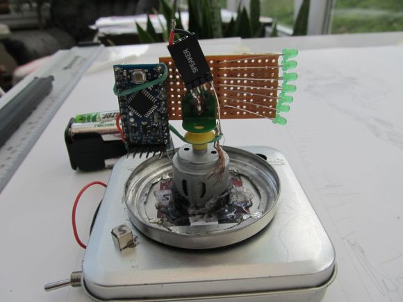
[Harrison] has been busy finding the sweeter side of quarantine by building a voice-controlled, face-tracking M&M launcher. Not only does this carefully-designed candy launcher have control over the angle, direction, and velocity of its ammunition, it also locates and locks on to targets by itself.

Here comes the science: [Harrison] tricked Alexa into thinking the Raspberry Pi inside the machine is a smart TV named [Chocolate]. He just tells an Echo to increase the volume by however many candy-colored projectiles he wants launched at his face. Simply knowing the secret language isn’t enough, though. Thanks to a little face-based security, you pretty much have to be [Harrison] or his doppelgänger to get any candy.

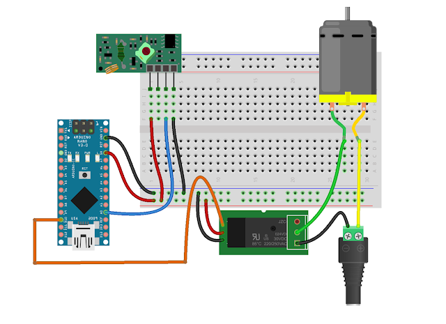
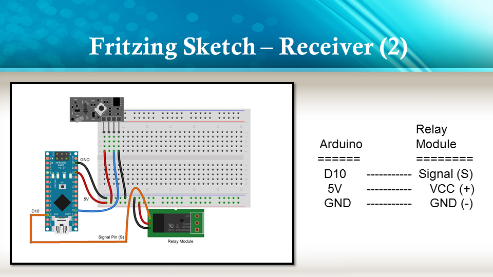
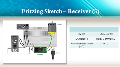
The Pi takes a picture, looks for faces, and rotates the turret base in that direction using three servos driven by Arduino Nanos. Then the Pi does facial landmark detection to find the target’s mouth hole before calculating the perfect parabola and firing. As [Harrison] notes in the excellent build video below, this machine uses a flywheel driven by a DC motor instead of being spring-loaded. M&Ms travel a short distance from the chute and hit a flexible, spinning disc that flings them like a pitching machine.

We would understand if you didn’t want your face involved in a build with Alexa. It’s okay — you can still have a voice-controlled candy cannon.

Eavesdropping Assistant Disturbs The Sound Of Silence

Unless you happen to be from Finland, this is just an all too familiar situation: you’re stuck in an inescapable situation with this one person who is really more of an acquaintance than a friend, and neither of you knows who should say something in hopes of keeping a conversation going. Awkward silence is inevitable, and the longer it lasts, the more excruciating the thought of opening your mouth becomes. Well, consider those days over, thanks to [Jasper Choi] and his friends, who blessed us with the System for Awkward Silence Solution and Interaction Enhancer, or SASSIE.

Built as a laser-cut rotating cylinder, and equipped with a pair of microphones, SASSIE detects and counts the duration of any ongoing silence in the room. Once a pre-defined time limit is reached, it rotates itself to a random direction, symbolically pointing a finger to one of the people present in the room to indicate its their turn to speak now. To break the silence right off the bat, the finger pointing is accompanied by some pre-recorded messages. Unfortunately the audio files exceeded the storage of the Arduino Uno used here, so the responsibilities had to be divided between two Arduinos, arranged with the help of some simple serial communication.

While this is obviously a tongue-in-cheek project, it might just be a welcoming relieve for people with social anxiety, and there is definitely potential to take the idea further. Maybe with some inspiration from this happy robot fellow, a future version might ease the conversation even further by suggesting a topic along the way.

Arduino Sumo Robot

Primary image

What does it do?

sumo robot


Before we start

What is the sumo robot?

It is a self-control robots with specific dimensions and features, it is also designed in a Hostile shape which qualify it to participate in the contests and competitions with other robots.

Cost to build

Embedded video

Finished project

Number

Time to build

Type

URL to more information

Weight

read more

Prextron CHAIN BLOCKS - Arduino Nano controlled Ultrasonic sensor that switches a motor wirelessly using 433MHz RF modules and a relay board.


Description

In this tutorial, I will be evaluating Prextron CHAIN blocks – a new system that allows you to connect your sensors and actuators to an Arduino NANO using clever 3D-printed prototyping boards that can be stacked sideways. This very modular system makes it easy to connect, disconnect and replace project components, and eliminate the “rats nest of wires” common to many advanced Arduino projects. CHAIN BLOCKS are open, which means that you can incorporate any of your sensors or actuators to these prototyping boards, and you can decide which specific pin on Arduino you plan to use. The CHAIN BLOCK connections prevent or reduce common connection mistakes, which make them ideal for class-room projects and learning activities.

I am going to set up a project to put these CHAIN BLOCKs to the test:
When I place my hand in-front of an Ultrasonic sensor, the Arduino will transmit a signal wirelessly to another Arduino, and consequently turn on a motor.


Parts Required:

You need the following Prextron Chain Blocks


Please note: You may need to solder the module wires to the CHAIN BLOCK protoboard.


Arduino Libraries and IDE

This project does not use any libraries. However, you will need to upload Arduino code to the Arduino. For this you will need the Arduino IDE which can be obtained from the official Arduino website:
https://www.arduino.cc/en/main/software


ARDUINO CODE: RF Transmitter


ARDUINO CODE: RF Receiver


Fritzing diagrams for Transmitter


Fritzing diagrams for Receiver


Concluding comments

The purpose of this project was to evaluate Prextron CHAIN BLOCKs and put them to the test. Here is what I thought of CHAIN BLOCKS at the time of evaluation. Some of my points mentioned below may no longer apply to the current product. It may have evolved / improved since then. So please take that into consideration


What I liked about Chain Blocks

  • The design is simple, the product is simple.
  • Once the Chain Blocks were all assembled, they were very easy to connect to each other.
  • I can really see the benefit of Chain Blocks in a teaching environment, because it simplifies the connection process, and reduces connection mixups.
  • It was good to see that the blocks come in different colours, which means that you can set up different colour schemes for different types of modules.
  • You can incorporate pretty much any sensor or Actuator into the Chain block which is very appealing.
  • You also have the flexibility of choosing which pins you plan to use on the Arduino.
  • Projects look a lot neater, because you no longer have the rats nest of wires.
  • The Blocks lock into each other which means that they are much easier to transport/carry.


What I did not like about Chain Blocks

  • In most cases, the Chain Block protoboard lanes were not numbered, which increased the chances of making mistakes when soldering
  • The need to solder modules to the protoboard, may be a discouragement for some people.
  • I would have liked a choice of different size Chain blocks. Some of the sensors did not fit nicely into the Square blocks.
  • Prextron really need to work on their website if they plan to get serious with this product: Webpage has incomplete functionality or irrelevant links etc etc.


Thank you very much to Prextron for providing the CHAIN BLOCKS used in this tutorial, and allowing me to try out their product. If you are interested in trying them yourself, then make sure to visit them at:


If you like this page, please do me a favour and show your appreciation :

 
Visit my ArduinoBasics Google + page.
Follow me on Twitter by looking for ScottC @ArduinoBasics.
I can also be found on Pinterest and Instagram.
Have a look at my videos on my YouTube channel.


Build a Persistence-of-Vision LED Globe

This isn't your typical schoolroom globe... Create a Persistence-of-Vision LED Globe to display a map, a skull, or message.

Read more on MAKE

The post Build a Persistence-of-Vision LED Globe appeared first on Make: DIY Projects and Ideas for Makers.

MAKE » Arduino 31 Aug 11:30

Strap a Robot to Your Face! Your Expressions Are Now Controlled by Technology

Turn an old headlamp into a power assist for your eyebrows. Use an infrared remote control to raise, lower, waggle, and adjust.

Read more on MAKE

The post Strap a Robot to Your Face! Your Expressions Are Now Controlled by Technology appeared first on Make: DIY Projects and Ideas for Makers.

Hack an Old DC Motor to Provide Rotary Input

Watch a Redditor share how he hacked a DC motor and hooked it up to an Arduino to use as an encoder.

Read more on MAKE

The post Hack an Old DC Motor to Provide Rotary Input appeared first on Make: DIY Projects, How-Tos, Electronics, Crafts and Ideas for Makers.

POV Display Does it on the Cheap

[Sholto] hacked together this ultra low-budget spinning display. He calls it a zoetrope, but we think it’s actually an LED based Persistence Of Vision (POV) affair. We’ve seen plenty of POV devices in the past, but this one proves that a hack doesn’t have to be expensive or pretty to work!

The major parts of the POV display were things that [Sholto] had lying around. A couple of candy tins, a simple brushed hobby motor, an Arduino Pro Mini, 7 green LEDs, and an old hall effect sensor were all that were required. Fancy displays might use commercial slip rings to transfer power, but [Sholto] made it work on the cheap!

The two tins provide a base for the display and the negative supply for the Arduino. The tins are soldered together and insulated from the motor, which is hot glued into the lower tin. A paper clip contacts the inside of the lid, making the entire assembly a slip ring for the negative side of the Arduino’s power supply. Some copper braid rubbing on the motor’s metal case forms the positive side.

[Sholto] chose his resistors to slightly overdrive his green LEDs. This makes the display appear brighter in POV use. During normal operation, the LEDs won’t be driven long enough to cause damage. If the software locks up with LEDs on though, all bets are off!

[Sholto] includes software for a pretty darn cool looking “saw wave” demo, and a simple numeric display. With a bit more work this could make a pretty cool POV clock, at least for as long as the motor brushes hold up!

[via Instructables]


Filed under: led hacks

confused about how to drive a rc car using arduino

hi folks, I am trying to build an autonomous car by attaching my arduino uno r3  to my rc car. Please pardon me if there are certain stuff I don't understand as my electronics knowledge has long vaporised since my education days and im starting from zero again.

In particular, i'm using this guide http://www.instructables.com/id/Autonomous-Control-of-RC-Car-Using-Arduino/?ALLSTEPS as my RC car is also using a RX-2B chip.

read more