Posts with «9v battery» label

Wood and Brass Drink Temperature Monitor Looks Good, Has Class

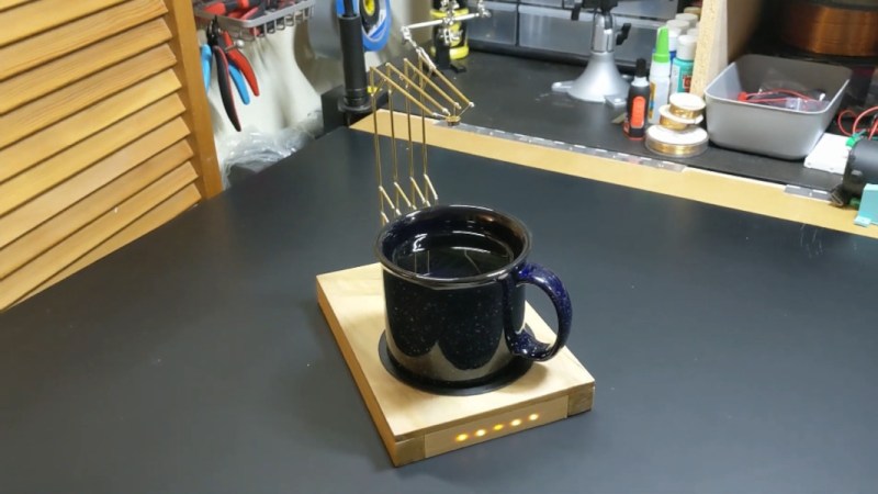
We’ve all been there. Your current project has hit a wall, or the next step will take days to complete, and you need something to do in the meantime. So you start a project that you envision will fit nicely in the gap, and then, inevitably, it doesn’t. Maybe it even takes so long that the original project gets finished first. So what? There’s nothing wrong with that, especially when the filler project turns out as well as this drink temperature monitor disguised as a circuit sculpture (video, embedded below). Just put your mug on the coaster, and the weight of it activates a hidden switch, which causes the sculpture to display its secret LEDs.

[MakeFunStuff] wanted to make something that looked less like a circuit and more like art, while building a tool that could determine the relative hotness of a beverage. Such a a useful circuit sculpture sounds like a tall order to us, but [MakeFunStuff] pulled it off with finesse and style.

The circuit is based around this Sputnik-looking standalone IR temperature sensor which, as [MakeFunStuff] aptly describes, is “a single-pixel infrared camera that picks up everything in a 90° cone starting at the sensor.”

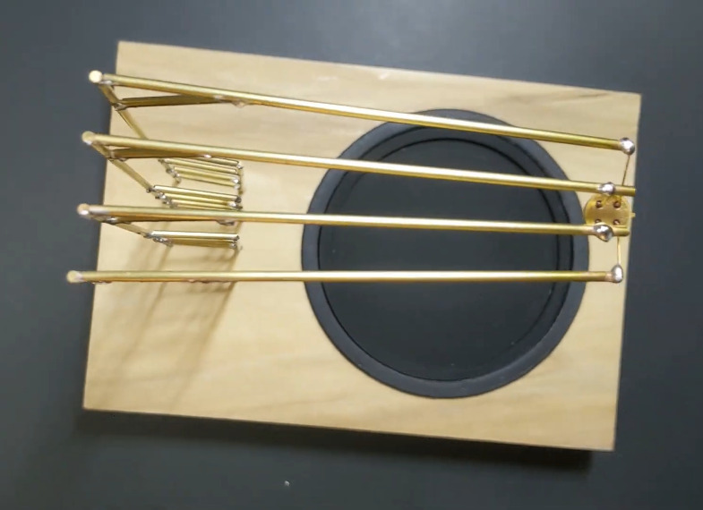
[MakeFunStuff] paired this easy-to-use sensor with an Arduino Nano and five LEDs that show how hot a beverage is on a scale from 1 to 5. The sensor is hidden in plain sight, suspended from the top of the brass rod sculpture and blending in perfectly. We love that the LEDs are hidden behind a thin layer of carefully-drilled wood and agree that a drill press would have been much easier.

The code is set up for just about every temperature scale from Celsius to Rømer, so that solves that argument. [MakeFunStuff] went with the Kelvin scale because science. Our favorite thing about this video is that [MakeFunStuff] shared their failures and fixes as they built their way toward answering the questions of how to suspend the sensor over the drink, and how best to display the heat level while hiding the electronics. Go grab a hot cup of something and check it out after the break while you let it cool off the normie way.

We admit that we would likely zone out while waiting for the LEDs to disappear. Here’s a smart coaster that uses an ESP8266 to send a message to Discord when your beverage has reached the perfect drinking temperature.

Thanks for the hot tip, [Perry]!

Arduino Sumo Robot

Primary image

What does it do?

sumo robot


Before we start

What is the sumo robot?

It is a self-control robots with specific dimensions and features, it is also designed in a Hostile shape which qualify it to participate in the contests and competitions with other robots.

Cost to build

Embedded video

Finished project

Number

Time to build

Type

URL to more information

Weight

read more

HomeMade IR Sensor Controlling Robot...Proof of Concept

Primary image

What does it do?

Navigates with IR Sensors

I saw a tutorial that Ro-Bot-X did on controlling a robot with homemade IR Sensors so i decided to try it.  I am using two 38KHz IR Reveivers from RadioShack and two IR LEDs from Radio Shack. 

Cost to build

Embedded video

Finished project

Number

Time to build

4 hours

Type

URL to more information

Weight

read more

BOXX-E

Primary image

What does it do?

Navigates via four HC-SR04 Ultrasonic Sensors

Parts:

Meduino Nano microcontroller

TB6612FNG motor driver on carrier board

Four HC-SR04 ultrasonic sensors

i2c serial LCD display - 16X2

1 TI MSP430 Launchpad box

1 TI Stellaris Launchpad box

Tamiya twin motor gearbox

Tamiya truck tires

Tamiya ball caster Power switch

IDE ribbon cable

2 430 contact breadboards

AA battery pack

9V battery connector

Zip ties

Wire

You can read more at my blog: http://www.meanpc.com

Cost to build

$70,00

Embedded video

Finished project

Number

Time to build

5 hours

Type

wheels

URL to more information

Weight

907 grams

3-axis accelerometer motion detector project

Description:
A 3-axis accelerometer sits at the heart of this project to provide a nifty little motion detector. Want to know who is stealing from the cookie jar? Want a simple home intrusion detector? Or to test your partner's driving skills? Then have a look at this:

(Soldering required for this project)


Video:


Parts Required:


Instructions:

  1. Overlay the Seeed Studio Base Shield onto the Freetronics Eleven (or compatible Arduino).
  2. Use a Universal Cable to attach a Seeed Studio Grove Button to Analog Pin 0 on the Base Shield. The socket is located directly above the Freetronics Eleven Power plug, and next to the Reset button on the Base Shield. Please note that Analog Pin 1 is not used by the Grove Button.
  3. Use a universal Cable to attache a Seeed Studio Grove Buzzer to Analog Pin 1 on the Base Shield. This is the socket next to the one used in Step 2.
  4. Solder the female header pins to the Protoboard. Overlay the protoboard onto the Base Shield to create a third layer. I created this layer to tidy up the project and make it a little bit more portable. You could just wire up another breadboard on the side.
  5. Stick a mini-breadboard (4.5cm x 3.5cm) onto the protoboard. This allows you to use the protoboard for other projects.
  6. Solder the male headers to the 3-axis accelerometer, and then place it centrally onto the breadboard.
  7. You need 5 wires to connect:
    • GND on protoboard to GND on accelerometer
    • 5V on protoboard to     VIN on accelerometer
    • Analog Pin 3 on protoboard to X on accelerometer
    • Analog Pin 4 on protoboard to Y on accelerometer
    • Analog Pin 5 on protoboard to Z on accelerometer
  8. Connect digital pin 8 to an LED and 330 ohm resistor on the breadboard,
  9. Use a wire to connect the resistor mentioned above to GND on the protoboard
  10. Connect the USB cable from your computer to the Freetronics Eleven, and upload the Arduino Sketch to the board. 
  11. Disconnect the USB cable, and then power the Freetronics Eleven using a 9V battery and clip.
  12. When you press the button, it will sound 3 warning sounds before it becomes activated.
  13. If it detects a vibration or motion that exceeds the tolerance level, it will alarm. The alarm will continue until you either press the Grove button - which resets and reactivates the device or you can press the Reset button on the Base Shield to Stop monitoring for motion.


Sketch


Freetronics Eleven / Arduino Sketch:

 1
2
3
4
5
6
7
8
9
10
11
12
13
14
15
16
17
18
19
20
21
22
23
24
25
26
27
28
29
30
31
32
33
34
35
36
37
38
39
40
41
42
43
44
45
46
47
48
49
50
51
52
53
54
55
56
57
58
59
60
61
62
63
64
65
66
67
68
69
70
71
72
73
74
75
76
77
78
79
80
81
82
83
84
85
86
87
88
89
90
91
92
93
94
95
96
97
98
99
100
101
102
103
104
105
106
107
108
109
110
111
112
113
114
115
116
117
118
119
120
121
122
123
124
125
126
127
128
129
130
131
132
133
134
135
136
137
138
139
140
141
142
143
144
145
146
147
148
149
150
151
152
153
154
155
156
157
158
159
160
161
162
163
164
165
166
167
168
169
170
171
172
173
174
175
176
177
178
179
180
181
182
183
184
185
186
187
188
189
190
191
192
193
194
195
196
197
198
199
200
201
202
203
204
205
206
207
208
209
210
211
212
213
214
215
216
217
218
219
//Motion Detector Alarm - Written by ScottC on 2/08/2012

//Global Variables and constants
const int buttonPin = A0; // button Pin connected to Analog 0
const int buzzerPin = A1; // buzzer Pin connected to Analog 1


//Accelerometer Pins
const int x = A3; // X pin connected to Analog 3
const int y = A4; // Y pin connected to Analog 4
const int z = A5; // Z pin connected to Analog 5


//Alarm LED
const int ledPin = 8; // LED connected to Digital 8


int tolerance=20; // Sensitivity of the Alarm
boolean calibrated=false; // When accelerometer is calibrated - changes to true
boolean moveDetected=false; // When motion is detected - changes to true


//Accelerometer limits
int xMin; //Minimum x Value
int xMax; //Maximum x Value
int xVal; //Current x Value

int yMin; //Minimum y Value
int yMax; //Maximum y Value
int yVal; //Current y Value

int zMin; //Minimum z Value
int zMax; //Maximum z Value
int zVal; //Current z Value


void setup(){
//Begin Serial communication
Serial.begin(38400);

//Initilise LED Pin
pinMode(ledPin, OUTPUT);

}


void loop(){
// If the button is pressed, initialise and recalibrate the Accelerometer limits.
if(analogRead(buttonPin)>500){
calibrateAccel();
}

// Once the accelerometer is calibrated - check for movement
if(calibrated){
if(checkMotion()){
moveDetected=true;
}
}

// If motion is detected - sound the alarm !
if(moveDetected){
Serial.println("ALARM");
ALARM();
delay(1000);
}

}


//This is the function used to sound the buzzer
void buzz(int reps, int rate){
for(int i=0; i<reps; i++){
analogWrite(buzzerPin,900);
delay(100);
analogWrite(buzzerPin,0);
delay(rate);
}
}


// Function used to calibrate the Accelerometer
void calibrateAccel(){
// reset alarm
moveDetected=false;

//initialise x,y,z variables
xVal = analogRead(x);
xMin = xVal;
xMax = xVal;

yVal = analogRead(y);
yMin = yVal;
yMax = yVal;

zVal = analogRead(z);
zMin = zVal;
zMax = zVal;

// Calibration sequence initialisation sound - 3 seconds before calibration begins
buzz(3,1000);

//calibrate the Accelerometer (should take about 0.5 seconds)
for (int i=0; i<50; i++){
// Calibrate X Values
xVal = analogRead(x);
if(xVal>xMax){
xMax=xVal;
}else if (xVal < xMin){
xMin=xVal;
}

// Calibrate Y Values
yVal = analogRead(y);
if(yVal>yMax){
yMax=yVal;
}else if (yVal < yMin){
yMin=yVal;
}

// Calibrate Z Values
zVal = analogRead(z);
if(zVal>zMax){
zMax=zVal;
}else if (zVal < zMin){
zMin=zVal;
}

//Delay 10msec between readings
delay(10);
}

//End of calibration sequence sound. ARMED.
buzz(3,40);
printValues(); //Only useful when connected to computer- using serial monitor.
calibrated=true;

}


//Function used to detect motion. Tolerance variable adjusts the sensitivity of movement detected.
boolean checkMotion(){
boolean tempB=false;
xVal = analogRead(x);
yVal = analogRead(y);
zVal = analogRead(z);

if(xVal >(xMax+tolerance)||xVal < (xMin-tolerance)){
tempB=true;
Serial.print("X Failed = ");
Serial.println(xVal);
}

if(yVal >(yMax+tolerance)||yVal < (yMin-tolerance)){
tempB=true;
Serial.print("Y Failed = ");
Serial.println(yVal);
}

if(zVal >(zMax+tolerance)||zVal < (zMin-tolerance)){
tempB=true;
Serial.print("Z Failed = ");
Serial.println(zVal);
}

return tempB;
}


// Prints the Sensor limits identified during Accelerometer calibration.
// Prints to the Serial monitor.
void printValues(){
Serial.print("xMin=");
Serial.print(xMin);
Serial.print(", xMax=");
Serial.print(xMax);
Serial.println();

Serial.print("yMin=");
Serial.print(yMin);
Serial.print(", yMax=");
Serial.print(yMax);
Serial.println();

Serial.print("zMin=");
Serial.print(zMin);
Serial.print(", zMax=");
Serial.print(zMax);
Serial.println();

Serial.println("------------------------");
}


//Function used to make the alarm sound, and blink the LED.
void ALARM(){

//don't check for movement until recalibrated again
calibrated=false;

// sound the alarm and blink LED
digitalWrite(ledPin, HIGH);
buzz(4,20);
digitalWrite(ledPin, LOW);
}

Simple Simon

Primary image

What does it do?

Obstacle avoidance, education

I built this super basic robot as a start-here style bot for a presentation I'm doing in a few weeks. I wanted something I could demonstrate building in realtime to a group of boyscouts. Simon is built with an arduino, dfrobot protoshield, breadboard, 2 parallax continuous rotation servos, 2 solarbotics wheels, a caster and a digital ir sensor. The whole thing is built with double sided tape (fritz start-here bot style). I should be able to demonstrate assembling him and uploading his program in about 15 minutes during my presentation.

Cost to build

$80,00

Embedded video

Finished project

Complete

Number

Time to build

0.75 hours

Type

wheels

URL to more information

Weight

read more

Arduino RC Car

Primary image

What does it do?

Drives and avoids obstacles

I had bought a RC Car from walmart for about $15 to use with the Arduino Motorshield a while back (see here). Fortunately, I had taken some pictures before I removed the RC receiver circuit from it. Turns out that its lot more efficient to use the onboard controller along with an Arduino instead of using a motorshield. I didnt some research and found out that many “cheap” RC cars use the same Realtek TX2 & RX2 chips inside. I was lucky enough to find the same inside this RC car.

Cost to build

Embedded video

Finished project

Number

Time to build

Type

URL to more information

Weight

read more

n/a

n/a