Posts with «magnetometer» label

Building a Digital Compass With An Arduino

The magnetic compass has been a crucial navigational tool for around a thousand years or so, perhaps longer. While classical versions still work perfectly well, you can now get digital magnetometers that work in much the same way. [mircemk] decided to whip up a digital compass to demonstrate the value of these parts.

The build uses a HMC5883L magnetometer. While this can detect magnetic fields in three axes, just one is necessary for building a device that operates akin to a traditional compass. The output of the device is read by an Arduino Nano, which is hooked up to a string of WS2812B LEDs and a small OLED display. The LEDs display the bearing of magnetic north, while the OLED screen shows the current angle between the compass’s arrow and magnetic north.

It’s a tidy build that would be a great educational resource for teaching both electronics and navigational skills. We’ve seen similar projects before, like the hilarious Pizza Compass. Video after the break.

Hack a Day 12 Jul 21:00

Turning a Tic Tac box into a portable magnetometer

If you want a way to measure magnetic fields on the go, then look no further than this tiny device from Instructables user “rgco.”

The portable magnetometer was made using just a couple of common parts, including an SS49E linear Hall effect sensor, an Arduino Nano, a 0.96” OLED screen, and a push button.

All the electronics are concealed inside a Tic Tac box, which holds the components together and provides a window for the display. The SS49E itself is isolated from the rest of the unit via a ballpoint pen tube, which allows it to be placed in narrow openings without interference. 

For increased accuracy, the sensor was calibrated using a cylindrical electromagnet, and the project was prototyped using an Uno before being stuffed into its rather small enclosure.

Visualizing magnetic fields in three dimensions with an Arduino magnetometer

As humans, we can’t detect magnetic fields, but we take advantage of this phenomenon every day in the form of motors and various sensors. Even electrical wire produces a field when current flows through it. You can sense magnetism with a compass, but if you want to visualize it in three dimensions, maker ‘amamitof7’ has a solution in the form of this Arduino magnetometer.

The device uses a trio of analog Hall effect sensors to measure the strength of the magnetic field. This data is fed to a MKR WiFi 1010 (or Uno), which generates an isometric representation of the field on a small TFT display. 

One could see this used in a variety of diagnostic applications, or perhaps as an excellent physics teaching tool.

HMC5883L on the GY-80 module

Description

In this tutorial, I will show you how to configure and extract data from the magnetometer (HMC5883L) sensor on the GY-80 10DOF module from ICStation. While there are some very good libraries on the internet which will give you full access to this sensor, I will show you what you need to know without using a library. This means that it may get a bit technical at times, but I will hold your hand along the way and provide explanations as required. I would also recommend that you watch the complete video from start to finish - as the video provides really useful information.


HMC5883L Magnetometer Datasheet:

You can find the datasheet for the HMC5883L pretty easily by searching on the internet. Here are a couple of sources:


Arduino Libraries

This tutorial does not use any external libraries.
It does use the Wire library for I2C communication.
However, there is no extra download required to access the Wire library.
If you are looking for a library specific for the HMC5883L sensor, then I would recommend one of these:

Like I said - you do not need an HMC5883L library for this tutorial. The libraries above are listed for those who wish to learn more about this particular sensor.

Arduino IDE

The Arduino IDE can be downloaded from the Arduino website. Visit the Arduino IDE download page.

I generally use the ZIP file for Windows and never seem to have any issues.
There are downloads available for all the major operating systems.


ARDUINO CODE:

I have created a Gist for the Arduino code to configure and extract data from the HMC5883L sensor. However, I also have a GitHub repository which aims to capture the code for all of the sensors on the GY-80 module. Code for the other sensors will become available in due time. Meanwhile, have a look at the code below for the HMC5883L sensor:

This code will set all axis values to 1000 upon startup. Moving the GY-80 module around will result in a value greater or less than 1000, however, returning the sensor back to it's original position, should result in values very close to 1000 on each axis. I chose to introduce this calibration in order to avoid negative values, and I liked the fact that I could set a heading with values that were easy to remember.
 
The magSetting function was created to easily configure the magnetometer.
Make sure to look at the video and also the datasheet for further information about calibrating the magnetometer.
 
The getReadings function was created to easily retrieve the magnetometer axis data. I chose to use Single measurement mode in this tutorial.


Hooking it up:

You can communicate with any of the sensors on the GY-80 module using I2C. The HMC5883L magnetometer sensor is no different. You will need four connections between the Arduino UNO and the GY-80 module. Have a look at the diagram below for the connection diagram and table.

Fritzing diagram


Project pictures


Concluding comments

The HMC5883L sensor on the GY-80 module is quite interesting and works relatively well. There are a number of other sensors on the GY-80 module which can provide complementary positional data. At some point, I plan to come back and explain some of the other sensors on this module, but first I would like to create a real-life project using the magnetometer. So stay tuned. You may want to subscribe to my social networks or to this blog to be notified of that project when I complete it.

I would like to thank ICStation for their collaborative efforts. Their contribution was invaluable to this tutorial's existence.

If you like this page, please do me a favour and show your appreciation :

 
Visit my ArduinoBasics Google + page.
Follow me on Twitter by looking for ScottC @ArduinoBasics.
I can also be found on Pinterest and Instagram.
Have a look at my videos on my YouTube channel.

             
ScottC 06 Nov 16:20

Navigation Thing: Four Days, Three Problems, and Fake Piezos

The Navigation Thing was designed and built by [Jan Mrázek] as part of a night game activity for high school students during week-long seminar. A night-time path through a forest had stations with simple tasks, and the Navigation Thing used GPS, digital compass, a beeper, and a ring of RGB LEDs to provide a bit of “Wow factor” while guiding a group of students from one station to the next. The devices had a clear design direction:

“I wanted to build a device which a participant would find, insert batteries, and follow the beeping to find the next stop. Imagine the strong feeling of straying in the middle of the night in an unknown terrain far away from civilization trusting only a beeping thing you found. That was the feeling I wanted to achieve.”

The Navigation Things (there are six in total) guide users to fixed waypoints with GPS, a digital compass, and a ring of WS2812 LEDs — but the primary means of feedback to the user is a beeping that gets faster as you approach the destination. [Jan] had only four days to make all six units, which was doable. But as most of us know, delivering on a tight deadline is often less about doing the work you know about, and more about effectively handling the unexpected obstacles that inevitably pop up in the process.

The first real problem to solve was the beeping itself. “Beep faster as you get closer to the destination” seems like a simple task, but due to the way humans perceive things it’s more complex than it sounds. We perceive large changes easier than small incremental ones, so a straight linear change in beep frequency based on distance doesn’t work very well. Similar problems (and their solutions) exist whether you’re controlling volume, brightness, or just about anything else that humans perceive. Instead of encoding distance as a beep frequency, it’s much more effective to simply use beeps to signal overall changes: beep noticeably slower as you move away, but beep much faster as you get close.

A “piezo” buzzer that was assumed to have no significant magnetic field, but in fact contained a magnet.

The other interesting problems were less straightforward and were related to the digital compass, or magnetometer. The first problem was that the piezo buzzers [Jan] sourced contained no actual piezo elements. They contained magnets – which interfered with the operation of the digital compass. After solving that, still more compass problems arose. When testing the final units in the field, the compass readings were not as expected and [Jan] had no idea why.

After careful troubleshooting, the culprit was found: the AA cells on the other side of the circuit board. Every AA cell has a faint (and slightly different) magnetic field, and the proximity and placement of the cells with respect to the magnetometer was causing the deviation. Happily, the fix was simple once the problem was understood: calibrate the compass every time new batteries are inserted.

If you’re interested in the Navigation Thing, check out the github repository. And on the topic of actual piezoelectric devices, piezos are implemented in a variety of clever ways. There are even piezo transformers and piezo vacuum pumps.


Filed under: gps hacks, misc hacks

Wireless Water Meter Monitor Watches Waste

It’s no secret that hackers like to measure things. Good numbers lead to good decisions, like when to kick your wastrel teenager out of a luxuriously lengthy shower. Hence the creation of this wireless Arduino-based water meter interface.

We’ll stipulate that “wireless” is a bit of a stretch. Creator [David Schneider] chose to split the system into two parts – a magnetometer and an Arduino to sense impulses from the water company meter, and a Raspberry Pi to serve the web interface. The water meter is at the street rather than in his house, so the sensor is wired to the Pi with some telephone cable. But from there the system is wireless.

[David] goes into some good detail on the sensing problem he faced, which relies on detecting the varying magnetic field due to the spinny-bits inside the flowmeter and cleaning up the signal with the Arduino; he also addresses aliasing errors that occur when flow rate approaches the sampling rate of the magnetometer.

We like the fact that there’s a lot of potential to leverage this technique to monitor other processes with rotating magnetic fields. And like this optically coupled gas-meter monitor, it’s not invasive of the utility’s equipment either, which is a plus.

[via reddit]


Filed under: green hacks, home hacks

Visualizing Magnetic Fields In 3D Space

[John] is working on his PhD in experimental earthquake physics, and with that comes all the trials of becoming a PhD; tuning students into the cool stuff in the field, and demonstrating created after 1970 to his advisers. One of the biggest advancements in his line of work in the last 30 or 40 years is all those sensors you can find in your cell phone. The three-axis magnetometer in your phone is easily capable of measuring the Earth’s magnetic field, and this chip only costs a few dollars. To demonstrate this, [John] built a 3D compass to show off the capability of these sensors, and have a pretty light show for the undergrads.

The magnetometer [John] is using is just a simple I2C magnetometer that can be found on Adafruit or Sparkfun. It’s not really anything special, but with a little bit of code, [John] can read the magnetic field strength in the x, y, and z axes.

Having a microcontroller spit out a bunch of numbers related to the local magnetic field just doesn’t seem fun, so [John] picked up two neopixel rings – one inside the other, and set 90 degrees out of plane with each other. This turns his magnetometer and Arduino setup into a real 3D compass. With this device, the local magnetic field can be visualized in the x, y, and z axes. It looks cool, which is great for undergrads, and it’s a great demonstration of what you can do with small, cheap electronic sensors.

[John] put up a screencast of a talk he gave at the American Geophysical Union meeting last year. You can check that out below.


Filed under: Arduino Hacks
Hack a Day 21 Jun 18:00

MagnID – Sneaky New Way of Interacting With Tablets

New magnetic tech dubbed “MagnID” is being presented this weekend at Stanford’s annual TEI conference. It is a clever hack aimed to hijack a tablet’s compass sensor and force it to recognize multiple objects. Here is a sneak peek at the possibilities of magnetic input for tablets.

Many tablets come with some sort of triaxial magnetic sensor but as [Andrea] and [Ian]’s demo shows, they are only capable of passing along the aggregate vector of all magnetic forces. If one had multiple magnetic objects, the sensor is not able to provide much useful information.

Their solution is a mix of software and hardware. Each object is given a magnet that rotates at a different known speed. This creates complex sinusoidal magnetic fields that can be mathematically isolated with bandpass filters. This also gives them distance to each object. The team added an Arduino with a magnetometer for reasons unexplained, perhaps the ones built into tablets are not sufficient?

The demo video below shows off what is under the hood and some new input mechanics for simple games, sketching, and a logo turtle. Their hope is that this opens the door to all manner of tangible devices.

Check out their demo at Standford’s 9th annual “Tangible, Embedded, Embodied Interaction” this January 15-19, 2015.


Filed under: handhelds hacks, tablet pcs hacks

Fitting a sphere

Today I had to write a program to fit a sphere to a bunch of points that were supposedly near the surface of a sphere, but were noisy and sampled in a very biased way.  Since this is obviously not a new problem, I started out doing web research.  but I didn’t look for fitting a sphere, but for fitting a circle, since that is a simpler related problem.

I found a lot of papers, including several review papers, on how to fit a circle to a bunch of points.  The “obvious” method is to  do a least-squares fit to minimize the distance between the points and the circle, minimizing , where is the radius and is the center of the circle.  Unfortunately, that is a difficult problem to solve, and even numerical methods require a lot of iterations to get decent solutions.  What most people do is to change to a slightly different problem that optimizes a different fitness function.  For example, Kåsa’s method minimizes .

There is a very nice, but very formal, presentation of the methods in a paper by Vaughn Pratt from 1987: Direct Least-Squares Fitting of Algebraic Surfaces.  This paper introduced Pratt’s method, which was later slightly improved to make Taubin’s method. I did not read these original papers (other than skimming Pratt’s paper).  Kåsa’s paper (A curve fitting procedure and its error analysis. IEEE Trans. Inst. Meas. 25: 8–14) does not seem to be available on-line.  The IEEE digital library is missing the whole 1976 year.

I did find a recent paper that does careful error analysis of both the geometric approach and several of the algebraic approaches (including the most popular ones: Kåsa, Pratt, and Taubin):

Ali Al-Sharadqah and Nikolai Chernov
Error analysis for circle fitting algorithms
Electronic Journal of Statistics
Vol. 3 (2009) 886–911 ISSN: 1935-7524 DOI: 10.1214/09-EJS419

This paper shows that Taubin’s method is theoretically superior to Pratt’s which is theoretically superior to Kåsa’s (having less essential bias), and gives a very weak example showing it is also tru empirically.  More interestingly, it also gives a “hyperaccurate” algorithm that has less bias even than Taubin’s method.  I did not read the error analysis, but I did read the description of their Hyper algorithm and the implementations of it that Chernov has on his website.

Since I needed Python code, not Matlab code, and I needed spheres rather than circles, I spent a few hours today reimplementing Chernov’s Hyperfit algorithm.  I noticed that the basis suggested by Pratt for spheres, 
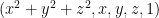
, was a simple modification of the one used in both Pratt’s paper and Chernov’s paper for circles, .  I decided to generalize to dimensions, and use the Numpy package in Python for all the matrix stuff.  I hope I got the generalization right!

From starting to look for papers until getting the code working was about 6 hours, but I had lunch in there as well, so this felt like pretty speedy development.  I’ve released the code with a Creative Commons Attribution-ShareAlike 3.0 Unported License, and would welcome corrections and improvments to it.

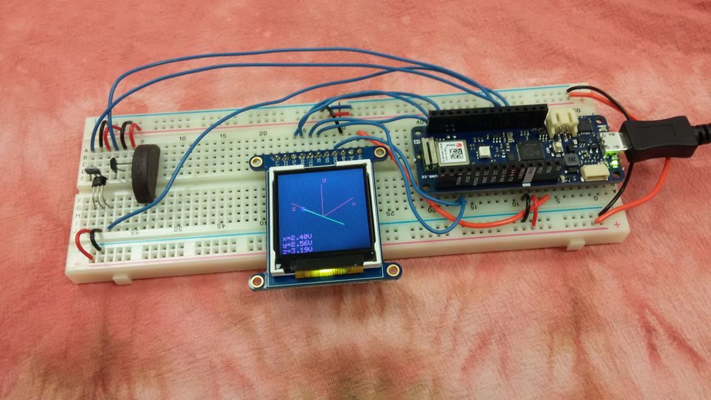
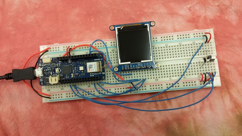
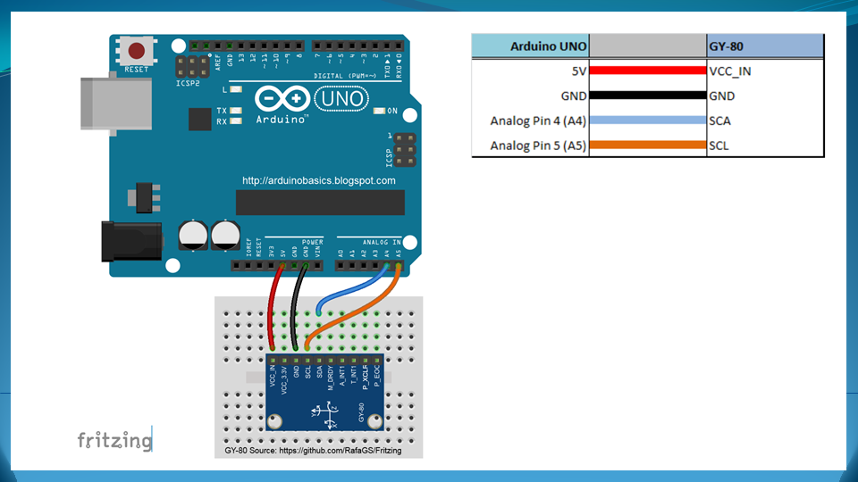
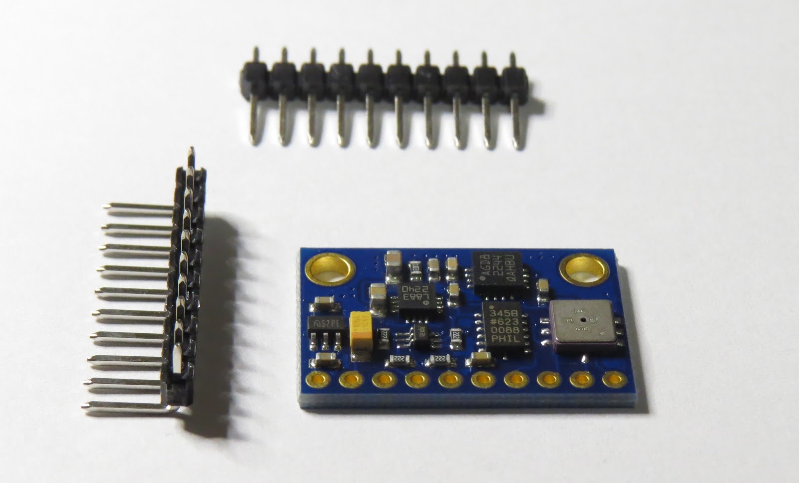
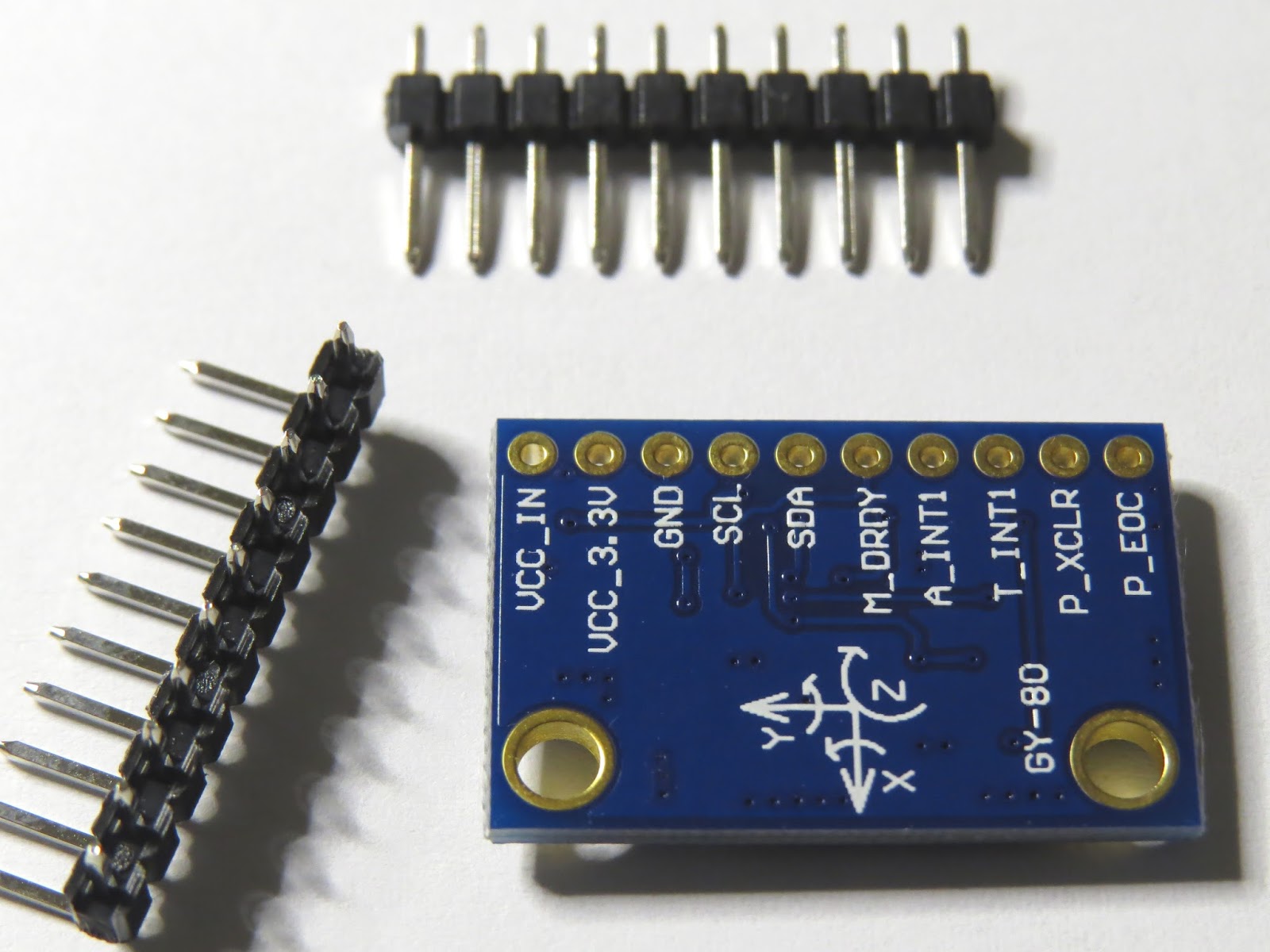
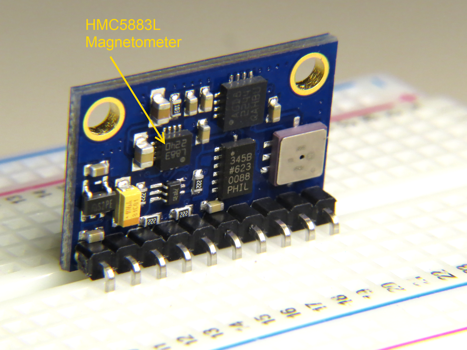
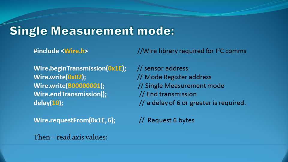
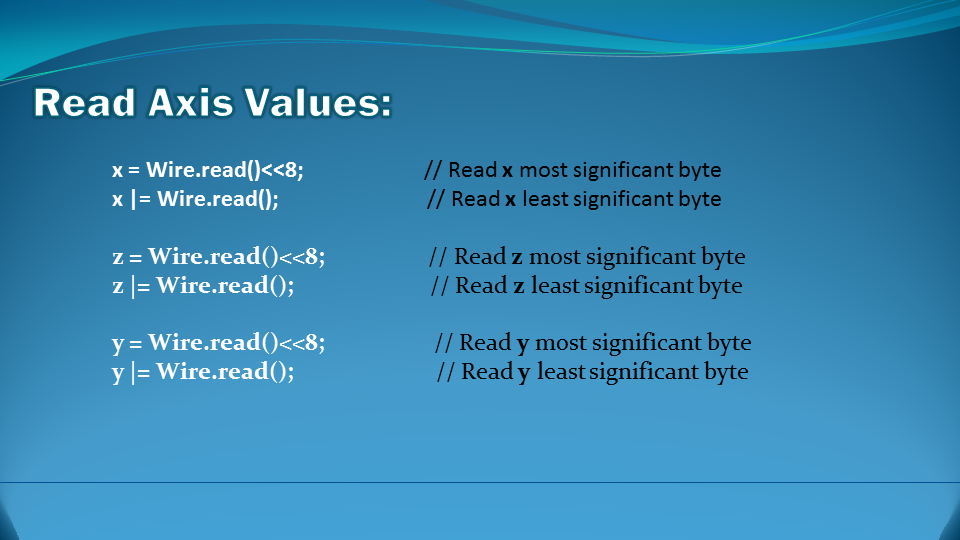
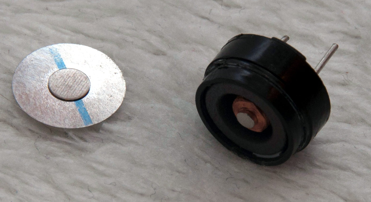
Of course, after all this buildup, you are probably wondering why I needed to fit a sphere to points—that is not a common problem for a bioinformatician to have.  Well, it is for the robotics club, of course.  They’ve been having a lot of trouble with the magnetometer calibration and heading code, so we decided to try doing an external calibration of the magnetometer, which has an enormous arbitrary 3D offset.  By waving the magnetometer around in different orientations (which means tumbling the ROV once the magnetometer is installed), we can sample the magnetic field in many orientations, though far from uniformly.  The center of  the sphere fitted to the readings gives us the 3D offset for the magnetometer.

My son and I tested it out with Python code and Arduino code that he had written to get the data from the magnetometer to the laptop, and the magnetometer readings do seem to be nicely centered around (0,0,0) after we do the correction.  We’re still having trouble using the accelerometer to get a tilt correction to give us clean compass headings, but that is a problem for tomorrow morning, I think.


Tagged: Arduino, circle fitting, magnetometer, NumPy, Python, sphere fitting