Any Old TV Can Be A Clock With Arduino
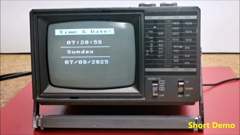
If you’ve got an old black and white TV, it’s probably not useful for much. There are precious few analog broadcasters left in the world and black and white isn’t that fun to watch, anyway. However, with a little work, you could repurpose that old tube as a clock, as [mircemk] demonstrates.
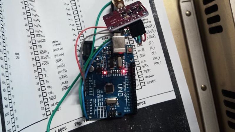
The build is based around an Arduino Nano R3. This isn’t a particularly powerful microcontroller board, but it’s good enough to run the classic TVOut library. This library lets you generate composite video on an Atmel AVR microcontroller with an absolute minimum of supporting circuitry. [mircemk] paired the Arduino with a DS3231 real-time clock, and whipped up code to display the time and date on the composite video output. He then also demonstrates how to hack the signal into an old TV that doesn’t have a specific input for composite signals.
You’ll note the headline says “any old TV can be a clock,” and that’s for good reason. Newer TVs tend to eschew the classic composite video input, so the TVOut library won’t be any good if you’re trying to get a display up on your modern-era flatscreen. In any case, we’ve seen the TVOut library put to good use before, too. Video after the break.