

Blinky the one-eyed Clock
This is a rewrite of a project I created in 2010 which brought me a lot of joy, so I hope you enjoy it too. Please read the entire article before starting your own. You can still make it today, the parts are easily available.
I’ve always enjoyed making Arduino-powered clocks, however over time they tended to become increasingly complex. So to counter this, allow me to introduce you to “Blinky” the one-eyed clock:
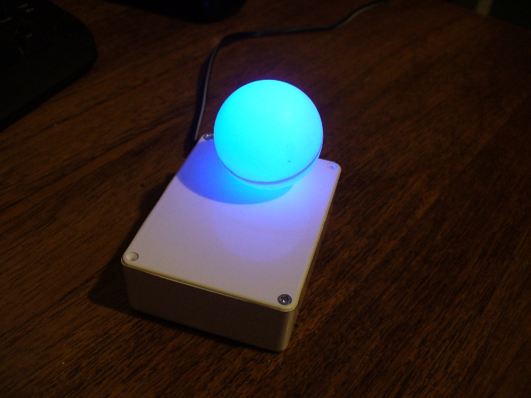
It reminds me of the giant killer orb “Rover” from “The Prisoner“… Using a minimal Arduino bootrom system, a DS1307 real time clock IC and an RGB diffused LED, you can make a clock that blinks the time, using the colours of the LED to note different numerical values.
For example, if the time is 12:45, the clock will blink red 12 times, then show blue for a second (think of this as the colon on a digital clock) then blink four times in green (for forty minutes), then blink three times in red for the individual minutes.
If there is a zero, blink blue quickly. Then the clock will not display anything for around forty seconds, then repeat the process. Here he (she, it?) is blinking the time:
Setting the clock is simple. It is set to start at 12:00 upon power up. So for the first use you have to wait until about five seconds before midday or midnight, then power it up. To save cost it doesn’t use a backup lithium battery on the real-time clock IC, but you could add one if required. So let’s get started.
The first thing to do was test the RGB LED for brightness levels, so I just connected it to the digital output pins of my Arduino-compatible board via suitable current-limiting resistors. Red, green and blue to D9, D10 and D11 respectively. Each LED is going to be different, so to ensure maximum brightness without causing any damage you need to calculate the appropriate resistor values.
This is quite easy, the formula is: resistor (ohms) = voltage drop / LED current So if you have a 5V supply, and LED that needs only 2 volts, and draws 20 milliamps (0.2 amps) , the calculation will be: resistor = (5-2)/0.02 = 150 ohms. To be safe I used 180 ohm resistors. The LED was tested with this simple sketch:
/*
blinky LED test
*/
int red = 2;
int green = 3;
int blue = 4;
int d = 300;
void setup()
{
pinMode(red, OUTPUT);
pinMode(green, OUTPUT);
pinMode(blue, OUTPUT);
}
void loop()
{
digitalWrite(red, HIGH);
delay(d);
digitalWrite(red, LOW);
delay(d);
digitalWrite(green, HIGH);
delay(d);
digitalWrite(green, LOW);
delay(d);
digitalWrite(blue, HIGH);
delay(d);
digitalWrite(blue, LOW);
delay(d);
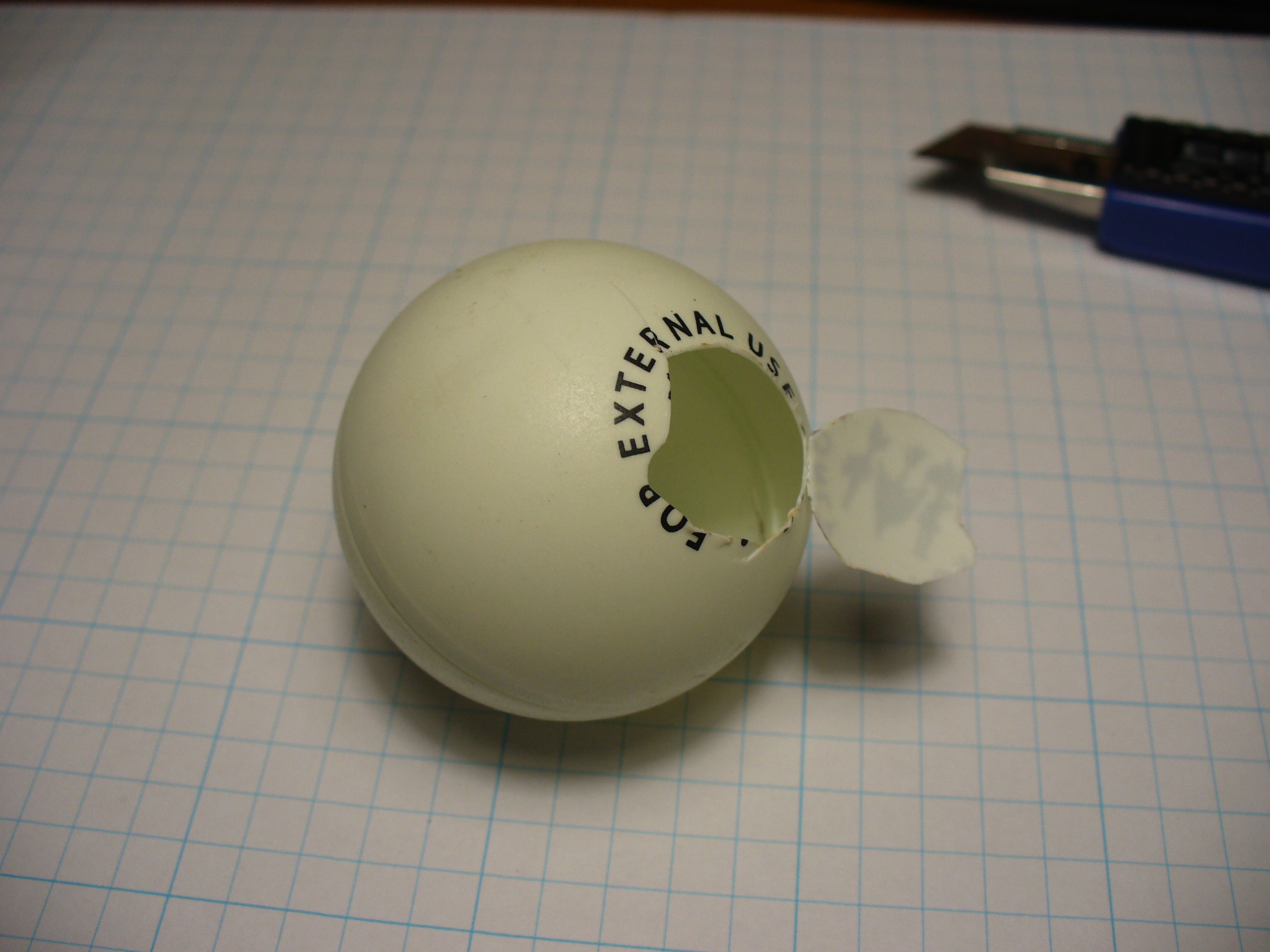
}It was interesting to alter the value of d, the delay variable, to get an idea for an appropriate blinking speed. Originally the plan was to have the LED in a photo frame, but it was decided to mount a ping-pong ball over the LED for a retro-style look. Here is a short video of the result of the test:
If you are going to use a ping-pong ball, please be careful when cutting into it with a knife, initially it may require a lot of force, but once the knife cuts through it does so very quickly.
Now it was time to develop the sketch to convert time into blinks. The sketch itself is quite simple. Read the hours and minutes from the DS1307 timer IC; convert the hours to 12 hour time; then blink an LED for the number of hours, display another colour for the colon; divide the minutes by ten and blink that in another colour; then the modulus of minutes and ten to find the individual minutes, and blink those out. Here is the first test sketch:
/*
"blinky" the one-eyed clock
Version beta 1
John Boxall August 2010/6th April 2022 - http://tronixstuff.com
DS1307/i2c timekeeping based on code by Maurice Ribble 17-4-2008 - http://www.glacialwanderer.com/hobbyrobotics
*/
#include "Wire.h"
#define DS1307_I2C_ADDRESS 0x68
int red = 9; // LEDs connected to these pins as you might want to PWM them to alter brightness
int green = 10;
int blue = 11;
// Convert normal decimal numbers to binary coded decimal
byte decToBcd(byte val)
{
return ( (val / 10 * 16) + (val % 10) );
}
// Convert binary coded decimal to normal decimal numbers
byte bcdToDec(byte val)
{
return ( (val / 16 * 10) + (val % 16) );
}
void setDateDs1307(byte second, // 0-59
byte minute, // 0-59
byte hour, // 1-23
byte dayOfWeek, // 1-7
byte dayOfMonth, // 1-28/29/30/31
byte month, // 1-12
byte year) // 0-99
{
Wire.beginTransmission(DS1307_I2C_ADDRESS);
Wire.write(0);
Wire.write(decToBcd(second)); // 0 to bit 7 starts the clock
Wire.write(decToBcd(minute));
Wire.write(decToBcd(hour));
Wire.write(decToBcd(dayOfWeek));
Wire.write(decToBcd(dayOfMonth));
Wire.write(decToBcd(month));
Wire.write(decToBcd(year));
Wire.write(0x10); // sends 0x10 (hex) 00010000 (binary) to control register - turns on square wave
Wire.endTransmission();
}
void getDateDs1307(byte *second,
byte *minute,
byte *hour,
byte *dayOfWeek,
byte *dayOfMonth,
byte *month,
byte *year)
{
// Reset the register pointer
Wire.beginTransmission(DS1307_I2C_ADDRESS);
Wire.write(0);
Wire.endTransmission();
Wire.requestFrom(DS1307_I2C_ADDRESS, 7);
*second = bcdToDec(Wire.read() & 0x7f);
*minute = bcdToDec(Wire.read());
*hour = bcdToDec(Wire.read() & 0x3f); // Need to change this if 12 hour am/pm
*dayOfWeek = bcdToDec(Wire.read());
*dayOfMonth = bcdToDec(Wire.read());
*month = bcdToDec(Wire.read());
*year = bcdToDec(Wire.read());
}
void blinkLED(int colour, int ondelay, int offdelay, int blinks)
// blinks LED on pin 'colour' for 'blinks' times with on and off delay of 'ondelay', 'offdelay'
// colour: 9 is red, 10 is green, 11 is blue
{
for (int a = 0; a < blinks; a++) {
digitalWrite(colour, HIGH); delay(ondelay); digitalWrite(colour, LOW); delay(offdelay);
}
}
void blinkTime() // blinks the time
{
byte second, minute, hour, dayOfWeek, dayOfMonth, month, year;
float aa;
int bb;
getDateDs1307(&second, &minute, &hour, &dayOfWeek, &dayOfMonth, &month, &year);
// convert hours from 24 to 12 hour time
if (hour == 0)
{
hour = 12;
}
if (hour > 12)
{
hour = hour - 12;
}
blinkLED(9, 500, 500, hour); // blink hours in red
blinkLED(11, 1000, 500, 1); // show blue for one second
aa = minute;
aa = aa / 10;
bb = int(aa); // find the value of tens of minutes (0~5)
if (bb > 0)
{
blinkLED(10, 500, 500, bb); // blink tens of minutes
}
if (bb == 0) // but if the time is something like 03:02?
{
blinkLED(11, 200, 200, 1); // blink blue quickly for zero
}
aa = minute % 10; // find modulo of minutes to get single minutes
if (bb > 0)
{
blinkLED(9, 500, 500, bb);
}
if (bb == 0)
{
blinkLED(11, 200, 200, 1); // blink blue quickly for zero
}
}
void setup()
{
byte second, minute, hour, dayOfWeek, dayOfMonth, month, year;
Wire.begin();
second = 0;
minute = 17;
hour = 4;
dayOfWeek = 6; // these values are moot, but need to store something
dayOfMonth = 28;
month = 5;
year = 10;
setDateDs1307(second, minute, hour, dayOfWeek, dayOfMonth, month, year);
pinMode(red, OUTPUT);
pinMode(green, OUTPUT);
pinMode(blue, OUTPUT);
}
void loop()
{
blinkTime();
delay(5000);
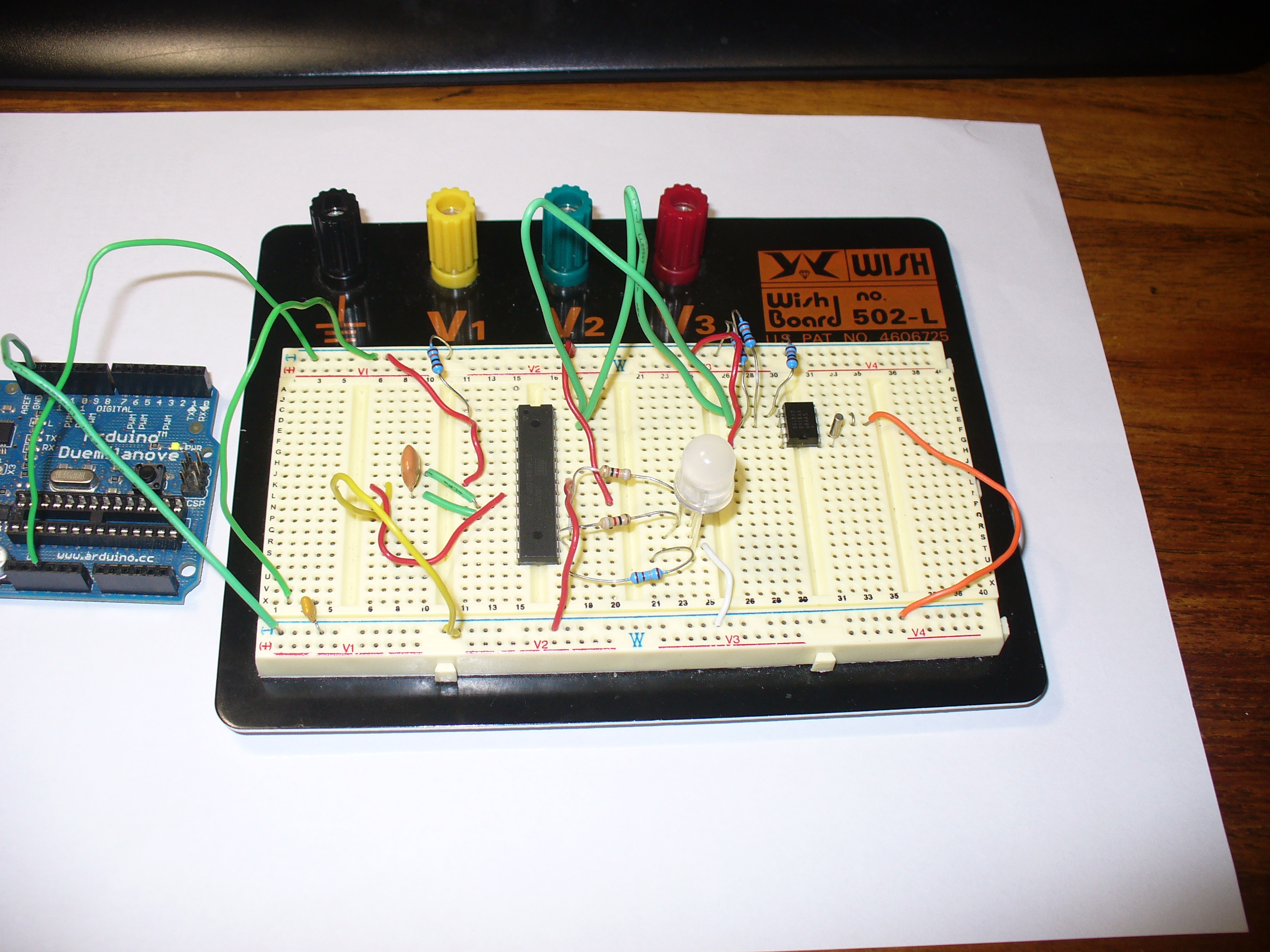
}Finally, the code was tested using the Arduino-compatible board and my home-made DS1307 real time clock shield (hey it was 2010, DS32xx were expensive). It is best to use existing hardware while testing, before committing to purchasing new hardware and so on. So here it is on the breadboard:
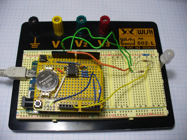
Here is the prototype in action:
If you’re wondering why the videos are potato-cam quality, smartphones couldn’t record using 4K Ultra HD in 2010.
But perhaps the first version was a little bland. By using analogWrite() we can control the brightness of the LED segments. So I’ve added two more functions, whiteGlow() and blueGlow(); whose purpose is to make the display “glow” by increasing then decreasing the brightness.
And I’ve scaled back the amount of blinking, to make blinky less obvious. So now the display will glow white to announce the forthcoming display of time, wait a second, blink the time (with a blue glowing colon) then stay dark for ten seconds before repeating the process. Here is a quick demonstration of this display style:
Here is the sketch for the above demonstration, and the final one I will use with the hardware prototype:
/*
  "blinky" the one-eyed clock - Version 2.1
  John Boxall 04 August 2010/6th April 2022
  IDGAF licence
  DS1307/i2c timekeeping based on code by Maurice Ribble
  17-4-2008 - http://www.glacialwanderer.com/hobbyrobotics
*/

#include "Wire.h"
#define DS1307_I2C_ADDRESS 0x68

int red = 9; // LEDs connected to these pins as you might want to PWM them to alter brightness
int green = 10;
int blue = 11;

// Convert normal decimal numbers to binary coded decimal
byte decToBcd(byte val)
{
  return ( (val / 10 * 16) + (val % 10) );
}

// Convert binary coded decimal to normal decimal numbers
byte bcdToDec(byte val)
{
  return ( (val / 16 * 10) + (val % 16) );
}

void setDateDs1307(byte second,        // 0-59
                   byte minute,        // 0-59
                   byte hour,          // 1-23
                   byte dayOfWeek,     // 1-7
                   byte dayOfMonth,    // 1-28/29/30/31
                   byte month,         // 1-12
                   byte year)          // 0-99
{
  Wire.beginTransmission(DS1307_I2C_ADDRESS);
  Wire.write(0);
  Wire.write(decToBcd(second));    // 0 to bit 7 starts the clock
  Wire.write(decToBcd(minute));
  Wire.write(decToBcd(hour));
  Wire.write(decToBcd(dayOfWeek));
  Wire.write(decToBcd(dayOfMonth));
  Wire.write(decToBcd(month));
  Wire.write(decToBcd(year));
  Wire.write(0x10); // sends 0x10 (hex) 00010000 (binary) to control register - turns on square wave
  Wire.endTransmission();
}

void getDateDs1307(byte *second,
                   byte *minute,
                   byte *hour,
                   byte *dayOfWeek,
                   byte *dayOfMonth,
                   byte *month,
                   byte *year)
{
  // Reset the register pointer
  Wire.beginTransmission(DS1307_I2C_ADDRESS);
  Wire.write(0);
  Wire.endTransmission();
  Wire.requestFrom(DS1307_I2C_ADDRESS, 7);
  *second     = bcdToDec(Wire.read() & 0x7f);
  *minute     = bcdToDec(Wire.read());
  *hour       = bcdToDec(Wire.read() & 0x3f);  // Need to change this if 12 hour am/pm
  *dayOfWeek  = bcdToDec(Wire.read());
  *dayOfMonth = bcdToDec(Wire.read());
  *month      = bcdToDec(Wire.read());
  *year       = bcdToDec(Wire.read());
}

void blinkLED(int colour, int ondelay, int offdelay, int blinks)
// blinks LED on pin 'colour' for 'blinks' times with on and off delay of 'ondelay', 'offdelay'
// colour: 9 is red, 10 is green, 11 is blue
{

  for (int a = 0; a < blinks; a++)
  {
    digitalWrite(colour, HIGH);
    delay(ondelay);
    digitalWrite(colour, LOW);
    delay(offdelay);
  }
}

void blinkTime()
// blinks the time
{
  byte second, minute, hour, dayOfWeek, dayOfMonth, month, year;
  float aa;
  int bb;
  getDateDs1307(&second, &minute, &hour, &dayOfWeek, &dayOfMonth, &month, &year);

  // convert hours from 24 to 12 hour time
  if (hour == 0)
  {
    hour = 12;
  }
  if (hour > 12)
  {
    hour = hour - 12;
  }
  blinkLED(9, 500, 500, hour); // blink hours in red
  blueGlow(1, 10);
  aa = minute;
  aa = aa / 10;
  bb = int(aa); // find the value of tens of minutes (0~5)
  if (bb > 0)
  {
    blinkLED(10, 500, 500, bb); // blink tens of minutes
  }
  if (bb == 0) // but if the time is something like 03:02?
  {
    blinkLED(11, 200, 200, 1); // blink blue quickly for zero
  }
  aa = minute % 10; // find modulo of minutes to get single minutes
  bb = aa;
  if (bb > 0)
  {
    blinkLED(9, 500, 500, bb); // blink tens of minutes
  }
  if (bb == 0)
  {
    blinkLED(11, 200, 200, 1); // blink blue quickly for zero
  }
}

void whiteGlow(int n, int d)
{
  for (int nn = 0; nn < n; nn++)
  {
    for (int a = 0; a <= 255; a++)
    {
      analogWrite(red, a);
      analogWrite(green, a);
      analogWrite(blue, a);
      delay(d);
    }
    for (int a = 255; a >= 0; --a)
    {
      analogWrite(red, a);
      analogWrite(green, a);
      analogWrite(blue, a);
      delay(d);
    }
  }
}

void blueGlow(int n, int d)
{
  for (int nn = 0; nn < n; nn++)
  {
    for (int a = 0; a <= 255; a++)
    {
      analogWrite(blue, a);
      delay(d);
    }
    for (int a = 255; a >= 0; --a)
    {
      analogWrite(blue, a);
      delay(d);
    }
  }
}

void setup()
{
  byte second, minute, hour, dayOfWeek, dayOfMonth, month, year;
  Wire.begin();
  second = 0;
  minute = 17;
  hour = 4;
  dayOfWeek = 6; // these values are moot, but need to store something
  dayOfMonth = 28;
  month = 5;
  year = 10;
  setDateDs1307(second, minute, hour, dayOfWeek, dayOfMonth, month, year); // every time blinky has new batteries, it will start from midnight/midday
  pinMode(red, OUTPUT);
  pinMode(green, OUTPUT);
  pinMode(blue, OUTPUT);
}

void loop()
{
  whiteGlow(1, 10); // glow white - announces that the time will now be shown
  delay(1000); // give people a second to focus on blinky
  blinkTime();
  delay(50000); // wait 50 seconds
}
Once happy with the sketch, I put a fresh ATmega328P-PU with Arduino bootloader in the board and programmed it with the sketch, to be used in the final version. The next step is to build my own hardware. The last hardware unknown is the amount of current the circuit draws. Once I know this the correct voltage regulator and power supply can be decided upon.
I had a fair idea it would be less than 100 milliamps, so I put a 6V battery onto supply duty via a 78L05 5V regulator (data sheet), and recorded the result:
So it varies, between 20.5 and 46 mA. As it only reaches 46 mA for a short time, we could consider the constant draw to be averaged out at 30 mA. I really want this to be able to run from a battery, but without having an external lead-acid battery lurking around, it will need a plug-pack with an output voltage greater than 7V DC.
Another alternative would be to run it from a USB socket, a nice source of 5V. If doing so, there wouldn’t be a need for the 78L05 regulator. Which brings us to the circuit diagram, which includes the power regulator. I’ve also altered the resistors to suit the RGB LED used, your values may be different:
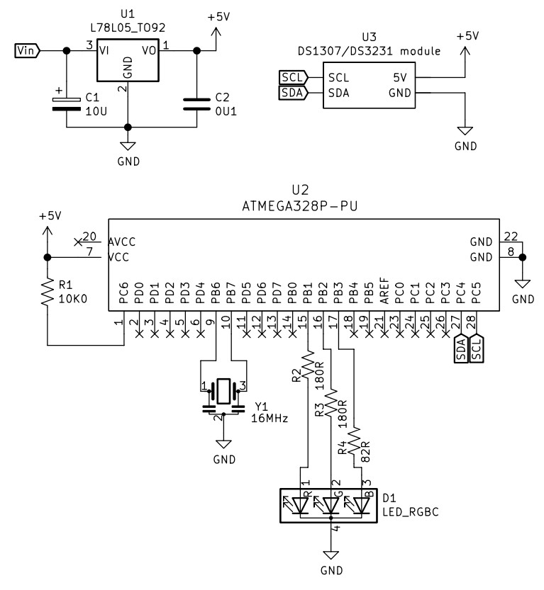
And since it’s 2022, not 2010 – I’ve replaced the DS1307 circuit with a RTC module. Y1 is a three pin 16MHz ceramic resonator, we used those in 2010 as they were cheaper and easier than a crystal and two 22pF capacitors.
The circuit does not allow for uploading code, so you will need to program the microcontroller on another Arduino or compatible board, then transfer it to the blinky circuit board as described above. At this stage you should test it again – but using a solderless breadboard. In doing so you can make final hardware checks, and generally make sure everything works as it should. This is also a good stage to double-check you are happy with the display behaviour, default time and so on.
Used the Duemilanove as a lazy 5V for testing.
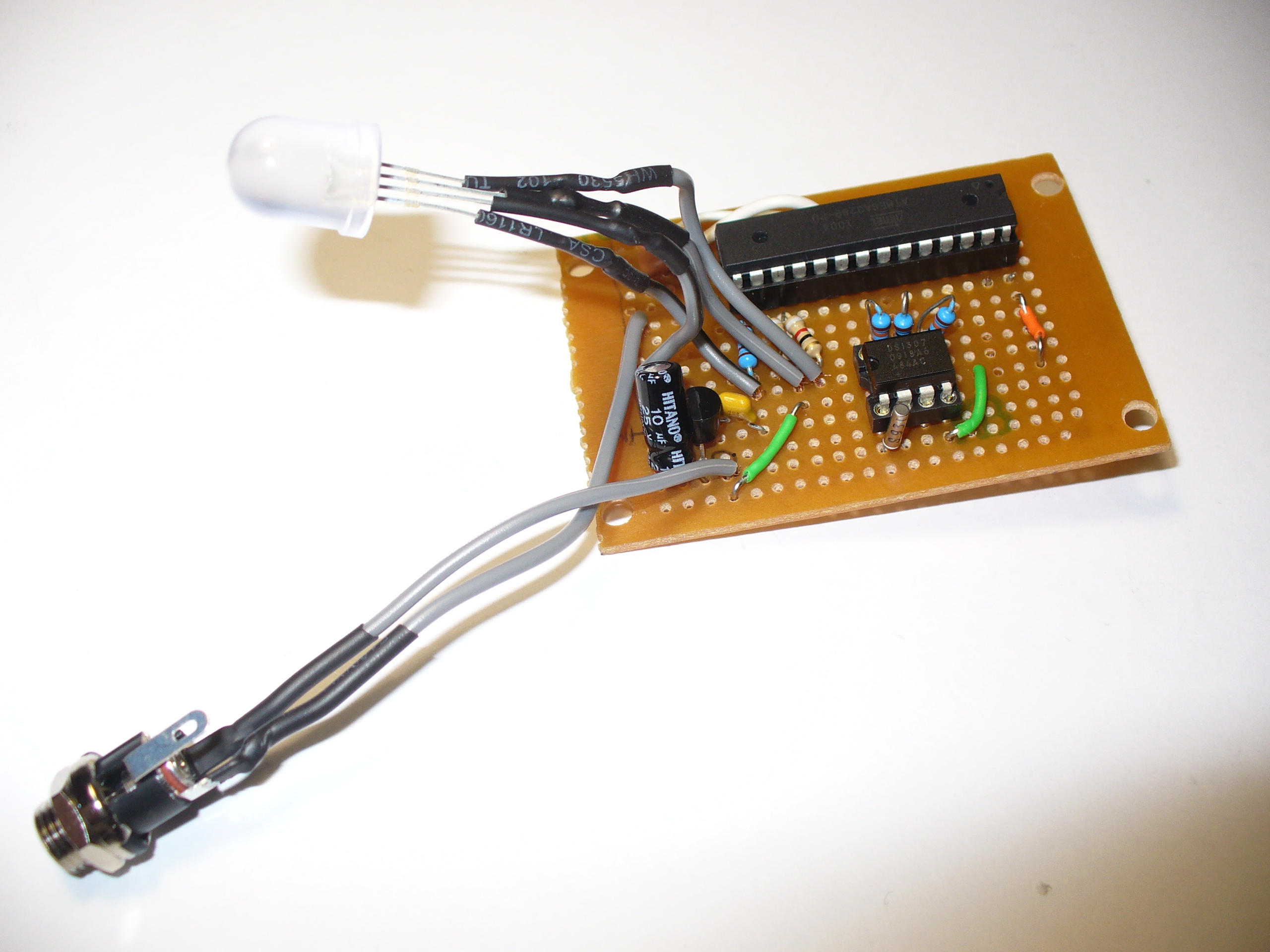
Time to solder up the circuit on some stripboard. Blank stripboard varies, but luckily I found this and a nice box to hold it in:
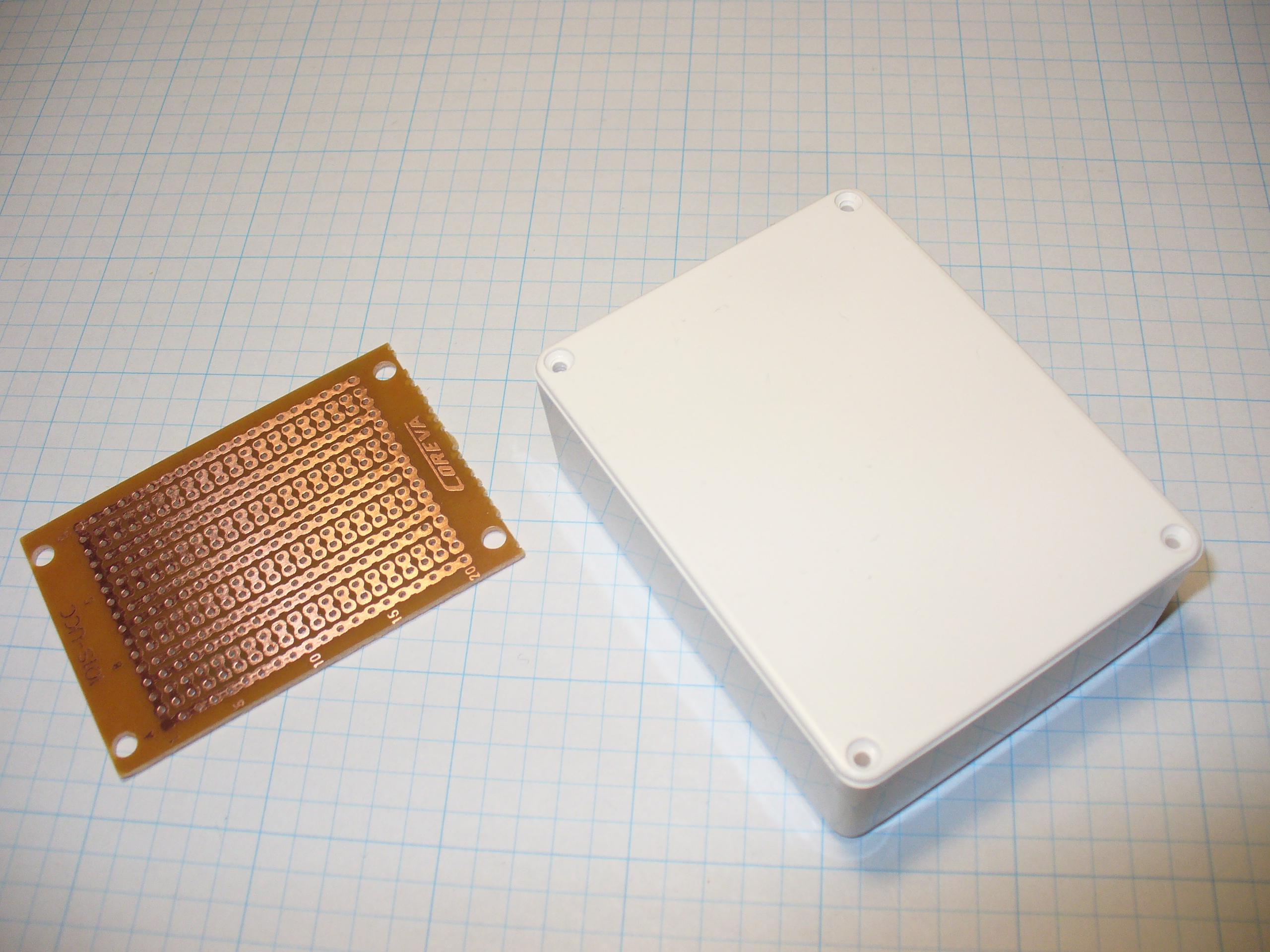
Stripboard does vary between retailers and so on, so you will need to work out the layout with your own board. In doing so, please double-check your work – follow the layout against the schematic and so on.
Have a break, then check it again. There is nothing worse than soldering away to realise you are one strip too far over or something. My hand-eye coordination is not the best, therefore my soldering isn’t pretty, but it works:
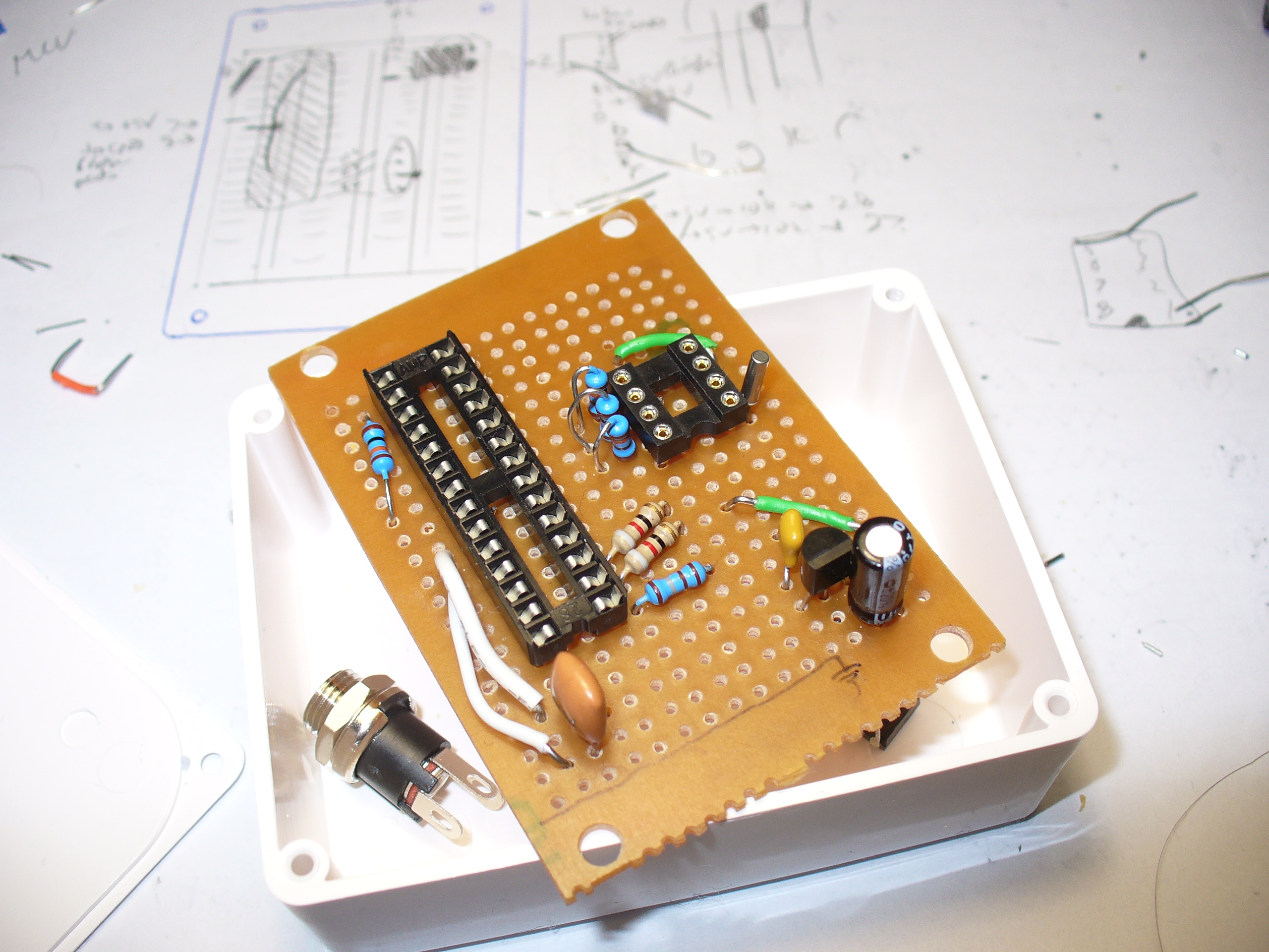
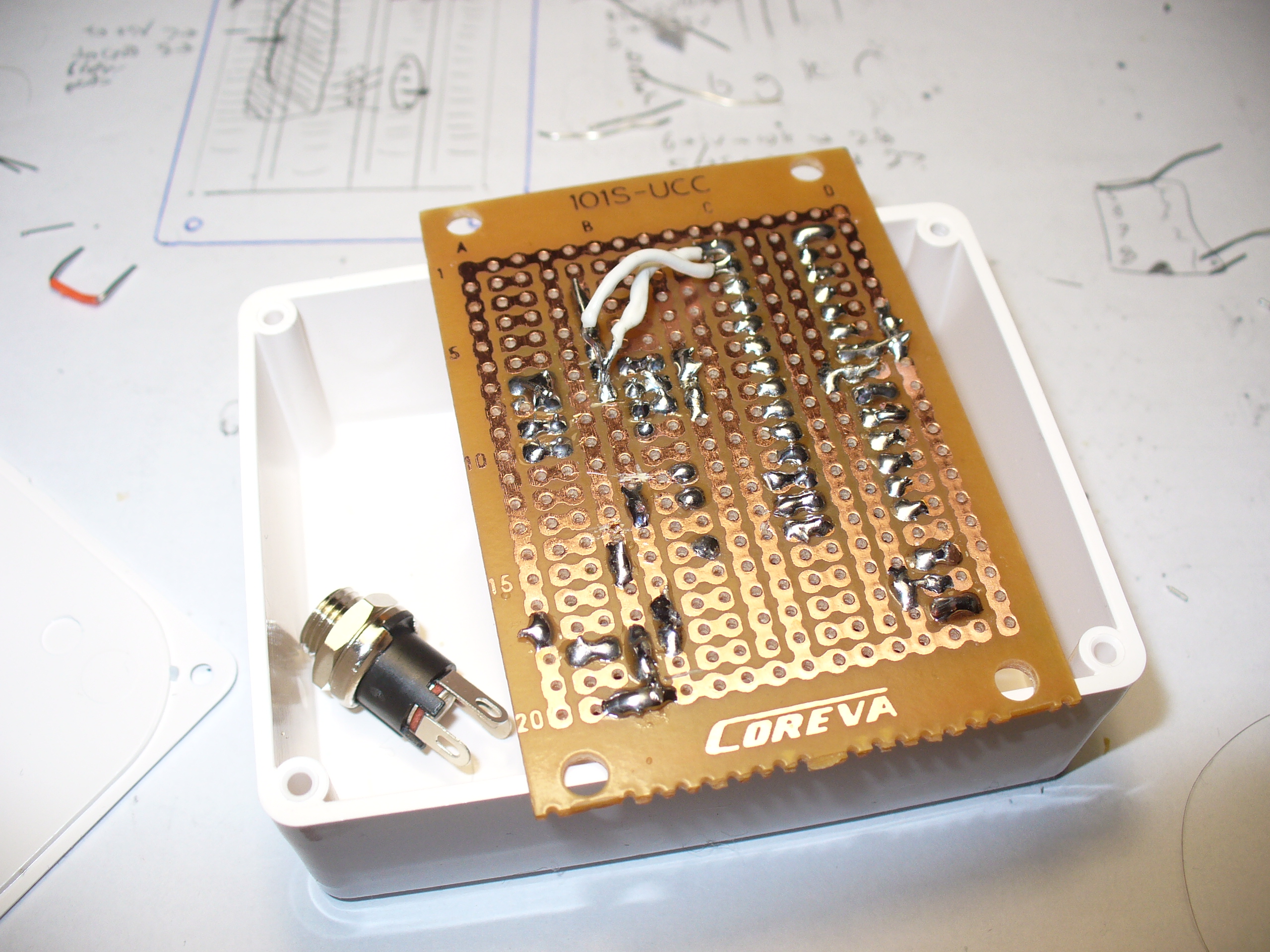
Note that the images above are using the 2010 circuit – which had a DS1307 sub-circuit.
One would say that there is a good argument for making your own PCBs… and I would agree with that. In 2010 it wasn’t that easy or inexpensive. Now you have KiCAD and Chinese PCB fabs tripping over themselves to give you cheap boards.
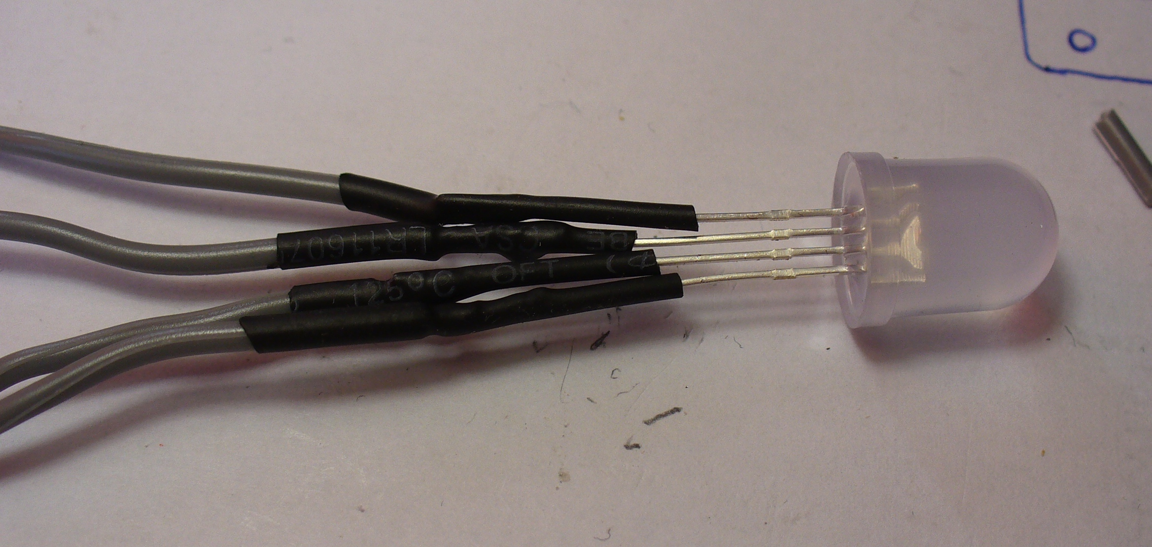
The LED is soldered to some short leads to give it a bit of play, and some heatshrink over the legs to keep them isolated:
And finally, to add a DC socket to feed blinky some power:
The last thing was to check the soldering once more under natural light, to check for bridges or shorts, then have a cup of tea. Upon my return I drilled out a hole in the enclosure lid for the LED, and one one the side for the DC socket, and fitted the lot together… and success! It worked.
I hope you enjoyed making this or at least reading about it. If you find this sort of thing interesting, please consider ordering one or both of my books from No Starch Press, or other book sellers:
- Arduino Workshop, 2nd Edition – a hands-on introduction to electronics and Arduino with 65 projects
- AVR Workshop – A comprehensive introduction to working with electronics and the Microchip AVR 8-bit family of microcontrollers with over 55 projects
And as always, have fun and make something.
[original story: Tronixstuff]