Posts with «sms» label

GPS Tracker Gets SMS Upgrade

In May of 2000, then-President Bill Clinton signed a directive that would improve the accuracy of GPS for anyone. Before this switch was flipped, this ability was only available to the military. What followed was an onslaught of GPS devices most noticeable in everyday navigation systems. The large amount of new devices on the market also drove the price down to the point where almost anyone can build their own GPS tracking device from scratch.

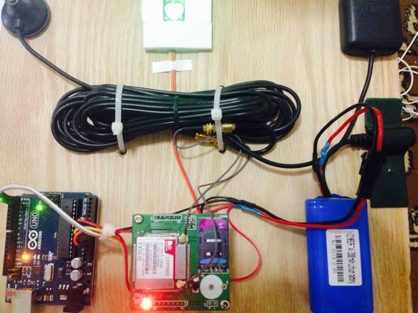
The GPS tracker that [Vadim] created makes use not just of GPS, but of the GSM network as well. He uses a Neoway M590 GSM module for access to the cellular network and a NEO-6 GPS module. The cell network is used to send SMS messages that detail the location of the unit itself. Everything is controlled with an ATmega328P, and a lithium-ion battery and some capacitors round out the fully integrated build.

[Vadim] goes into great detail about how all of the modules operate, and has step-by-step instructions on their use that go beyond what one would typically find in a mundane datasheet. The pairing of the GSM and GPS modules seems to go match up well together, much like we have seen GPS and APRS pair for a similar purpose: tracking weather balloons.


Filed under: gps hacks
Hack a Day 07 Jul 06:00
arduino  atmega328  atmega328p  cell  gps  gps hacks  gsm  sms  tracker  

Rotary Cell Phone: Blast from a Past that Never Was

The 1970s called and they want their rotary dial cell phone back.

Looking for all the world like something assembled from the Radio Shack parts department – remember when Radio Shack sold parts? – [Mr_Volt]’s build is a celebration of the look and feel of a hobbyist build from way back when. Looking a little like a homebrew DynaTAC 8000X, the brushed aluminum and 3D-printed ABS case sports an unusual front panel feature – a working rotary dial. Smaller than even the Trimline phone’s rotating finger stop dial and best operated with a stylus, the dial translates rotary action to DTMF tones for the Feather FONA board inside. Far from a one-trick pony, the phone sports memory dialing, SMS messaging, and even an FM receiver. But most impressive and mysterious is the dial mechanism, visible through a window in the wood-grain back. Did [Mr_Volt] fabricate those gears and the governor? We’d love to hear the backstory on that.

This isn’t the first rotary cell phone hybrid we’ve featured, of course. There was this GSM addition to an old rotary phone and this cell phone that lets you slam the receiver down. But for our money a rotary dial cell phone built from the ground up wins the retro cool prize of the bunch.

[via r/Arduino]


Filed under: Arduino Hacks, classic hacks

Arduino based Security Project Using Cayenne


Description

This is an Arduino based home security project that uses the power of "Cayenne" for extraordinary capabilities.

Cayenne Beta

Cayenne is a new IoT drag and drop platform originally released for the Raspberry Pi, but now available for Arduino. Cayenne makes the task of connecting your Arduino to the internet as simple as possible. All of the complexity of internet connectivity is hidden within the Cayenne library.

You can easily create a Network of Arduinos and build an IoT system which can be managed and operated within the Cayenne dashboard. This dashboard is accessible through your browser or via the Cayenne smart phone app (on IOS or Android).

The feature I liked the most, was the ability to change the position of sensors or actuators on the Arduino without having to re-upload Arduino code. I could manage the changed position from within the Cayenne platform. The other feature that I liked was the ability to setup actions based on custom triggers. You can use Cayenne to trigger a whole range of functions, for example: play a sound, move a motor, light up an LED, or to send alert notifications via email or SMS.

Cayenne is in Beta at the moment, so there are a few minor bugs here and there, but overall - I give it a thumbs up - it is definitely worth checking out.
 

Here is a link to the Cayenne Beta Program:
**Cayenne Beta Link**


              Source: myDevices Media Kit


Home Security Project Summary

In order to fully experience this new IoT platform, I decided to create a project to really put it through its paces. This is what my Security Project will need:

  1. It will use two Arduinos, one connected to the internet via an Ethernet shield, and the other via WIFI.
  2. Two detectors - a PIR sensor and a laser trip wire.
  3. If the sensors are tripped, the person has 10 seconds to present an RFID tag to the Grove RFID reader:
    • If a valid RFID tag is SUCCESSFULLY presented within the time limit, a nice personalised greeting will be played to that person using a Grove - Serial MP3 player
    • If a valid RFID FAILS to be presented within the time limit, an Alarm will sound, and I will be notified of the intrusion via an SMS alert.
  4. The Cayenne dashboard will show the status of the sensors, and I will have full control over my security system via the web interface (or smartphone app).
  5. The sensors will be attached to a different Arduino to that of the Grove MP3 player and the RFID tag reader, which means that there will have to be some level of communication between the two Arduinos. In fact, the cross communication will be vital to the success of this project.


Project Video


Flow Diagrams:

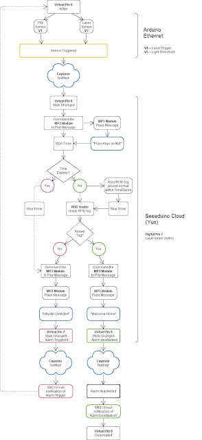
Main Flow Diagram

The following flow diagram shows the Security project process. It is a high level view of the decisions being made by each Arduino in response to various events.  


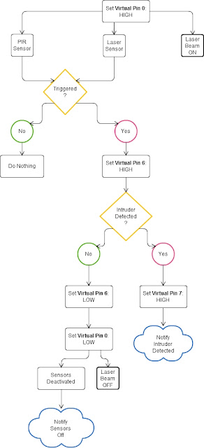
Triggers Flow Diagram

The following flow diagram aims to highlight the various triggers set up within Cayenne to get this Security system to work.  


Arduino IDE and Library Downloads

You will need an Arduino IDE to upload code to the Arduino and the Seeeduino Cloud.
Here is the link to the Arduino IDE: Arduino IDE - download location

The Cayenne service requires that you download and install the Cayenne Library into your Arduino IDE.
You can get the Cayenne Library from here: Cayenne Library File - Download


Cayenne Connectivity Setup

The Seeeduino Cloud needs to be prepared for use with Cayenne.
Normal operating/setup instructions can be found here: Seeeduino Cloud WIKI page
 
Once you have successfully connected Seeeduino Cloud to your WIFI network, you can add it to the Cayenne Dashboard by making the following selections from within the Cayenne Web application:

  1. Add New
  2. Device/Widget
  3. Microcontrollers
  4. Arduino
  5. Ensure Seeeduino Cloud is connected to WIFI network - the select the NEXT button
  6. Select - Arduino Yun: Built-in Ethernet - ticked
  7. Providing you have already installed the Cayenne library as described above - you should be able to copy and paste the code to the Arduino IDE and upload to the Seeeduino Cloud.
  8. If successful, you should see the Arduino Yun board appear within the Cayenne Dashboard. If not, then seek help within the Cayenne forum.


The Arduino UNO with WIZNET 5100 - Ethernet Shield
also needs to be prepared with Cayenne

  1. Add New
  2. Device/Widget
  3. Microcontrollers
  4. Arduino
  5. Ensure Arduino is powered, and Ethernet shield is connected to your internet router via an Ethernet cable
  6. Select - Arduino Uno: Ethernet Shield W5100 - ticked
  7. Copy and paste the code to the Arduino IDE and upload to the Arduino UNO.
  8. If successful, you should see the Arduino Uno board appear within the Cayenne Dashboard. If not, then seek help within the Cayenne forum.


If you have the Ethernet shield with the WIZNET 5200 chip, then you may need to download a specific Ethernet library in addition to the Cayenne library.
 
Just follow the instructions within the Automatically generated sketch provided - when you select your specific Arduino/Ethernet/WIFI shield combination. If you need further instructions on connecting your device to Cayenne - then please visit the myDevices website for the online documentation.


ARDUINO CODE (1)


Code for Arduino UNO with Ethernet Shield:

The following code will need to be uploaded to the Arduino UNO:


ARDUINO CODE (2)


Code for Seeeduino Cloud:

The following code will need to be uploaded to the Seeeduino Cloud:


Fritzing diagram (1)


Fritzing diagram for Arduino UNO with Ethernet

Please click on the picture below for an enlarged version of this fritzing diagram


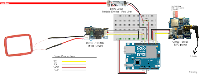
Fritzing diagram (2)


Fritzing diagram for Seeeduino Cloud

Please click on the picture below for an enlarged version of this fritzing diagram


Cayenne Dashboard Setup - GUI


The Arduino code only provides half of the functionality of this project. The Cayenne Dashboard needs to be setup to provide the rest of the functionality. The following instructions will show you how to add each of the widgets required for this Home Security project.


Arduino Ethernet - Master Switch

The master switch allows me to turn the security system on and off. When I turn the MASTER SWITCH ON, the laser beam will turn on, and the sensors will start monitoring the area for intruders. This widget is NOT associated with a physical switch/sensor on the Arduino - it uses virtual channel 0. We need to add the Master switch to the dashboard:


  1. Add New
  2. Device/Widget
  3. Actuators
  4. Generic
  5. Digital Output - Control a Digital Output
  6. Widget Name: Master On Off Switch
  7. Select Device: Arduino Ethernet
  8. Connectivity: Virtual
  9. Pin: V0
  10. Choose Widget: Button
  11. Choose Icon: Valve
  12. Step2: Add Actuator
We will add a trigger later to get this button to automatically turn the Laser beam on.


Arduino Ethernet - PIR Sensor

This sensor will be used to detect movement in the room. If a person walks into the room, this sensor will detect movement, and will trigger a message to be played on the Grove Serial MP3 player. The message will aim to get the person to identify themselves. They identify themselves by placing their RFID tag in close proximity to the Grove RFID reader. If the tag is valid, a "Welcome home" message is played on the Grove MP3 player. If a valid tag is not presented to the reader within 10 seconds, an Alarm will go off ("Alarm sound" played on Grove MP3 player.)
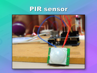
The PIR sensor is connected to digital Pin 6 of the Arduino, however, it is mapped to virtual pin 1 for better synchronisation with the Cayenne dashboard. This was done to capture ALL detections - as the PIR sensor could change from a LOW to HIGH and back to LOW state in between a Cayenne state check - and therefore, Cayenne could miss this motion detection.. Therefore we need to assign the PIR sensor to a virtual channel in the following way:
  1. Add New
  2. Device/Widget
  3. Sensors
  4. Motion
  5. Digital Motion Sensor - Motion Detector
  6. Widget Name: PIR sensor
  7. Select Device: Arduino Ethernet
  8. Connectivity: Virtual
  9. Pin: V1
  10. Choose Widget: 2-State Display
  11. Choose Icon: Light
  12. Step2: Add Sensor
  13. Select Settings from the PhotoResistor
  14. Choose Display: Value
  15. Save


Arduino Ethernet - Photoresistor

This sensor will be used with the laser beam to create a laser tripwire. If the sensor detects a change in light levels (drops below the threshold), it will activate the laser trigger button on the dashboard. The person will then be required to identify themselves etc etc (similar to the motion detection by the PIR sensor). The photoresistor widget will display the raw analog reading from the sensor (connected to A2), but is associated with virtual channel 2. I used a virtual channel for more control over this sensor. To add the Photoresistor to the dashboard:

  1. Add New
  2. Device/Widget
  3. Sensors
  4. Luminosity
  5. Photoresistor - Luminosity sensor
  6. Widget Name: PhotoResistor
  7. Select Device: Arduino Ethernet
  8. Connectivity: Virtual
  9. Pin: V2
  10. Choose Widget: Value
  11. Choose Icon: Light
  12. Step2: Add Sensor


Arduino Ethernet - Laser Trigger

The laser trigger is just an indicator that someone tripped the laser beam. The state of this widget is used to notify the Seeeduino that a presence has been detected. This widget is associated with virtual pin 4 on the Arduino UNO with Ethernet.

  1. Add New
  2. Device/Widget
  3. Actuators
  4. Generic
  5. Digital Output - Control a Digital Output
  6. Widget Name: Laser Trigger
  7. Select Device: Arduino Ethernet
  8. Connectivity: Virtual
  9. Pin: V4
  10. Choose Widget: Button
  11. Choose Icon: Lock
  12. Step2: Add Actuator


Arduino Ethernet - Laser Threshold

The laser threshold is used to manually configure the light level at which the laser trigger will trip. When the photoresistor value drops below the threshold value, the laser trigger icon will activate. This allows the threshold value to be updated from the Cayenne dashboard, rather than having to manually adjust the value in the Arduino code. Also, this threshold can be set remotely, in that you don't have to be near the Arduino to change this value. A very useful feature of this Security system. This widget is associated with virtual pin 5 on the Arduino UNO with Ethernet.

  1. Add New
  2. Device/Widget
  3. Actuators
  4. Generic
  5. PWM Output - Control a PWM Output
  6. Widget Name: Laser Threshold
  7. Select Device: Arduino Ethernet
  8. Connectivity: Virtual
  9. Pin: V5
  10. Choose Widget: Slider
  11. Slider Min Value: 0
  12. Slider Max Value: 10
  13. Step2: Add Actuator
The max value of the slider is 10 - due to a current bug in the Cayenne software. Once resolved, this value (as well as the relevant Arduino code) will need to be updated.


Seeeduino Cloud - Presence Detected

The presence detected widget is there to notify the Seeeduino Cloud that a presence has been detected on the Arduino Uno with Ethernet shield. When the PIR sensor detects movement or if the laser tripwire is tripped, Cayenne will change the state of the Presence Detected widget from LOW to HIGH. This is used within the Seeeduino Cloud to trigger the message "Place your keys on the Mat"
. If a valid RFID tag is read by the Grove RFID reader, then this widget's state will change back from HIGH to LOW, and the MasterSwitch will be deactivated - turning the Security system off. This widget is associated with Virtual pin 6 on the Seeeduino Cloud.

  1. Add New
  2. Device/Widget
  3. Actuators
  4. Generic
  5. Digital Output - Control a Digital Output
  6. Widget Name: Presence Detected
  7. Select Device: Seeeduino Cloud
  8. Connectivity: Virtual
  9. Pin: V6
  10. Choose Widget: Button
  11. Choose Icon: Lock
  12. Step2: Add Actuator


Seeeduino Cloud - Intruder Alert

If a valid RFID tag is not read by the Grove RFID reader within 10 seconds of a presence detection event, an alarm will sound, and this widget will be activated. This will trigger a notification event - to notify me of the unauthorised intrusion - via SMS or email. I will also have a visual indicator on the Cayenne dashboard that an intrusion has taken place. This widget is associated with Virtual pin 7 on the Seeeduino Cloud.

  1. Add New
  2. Device/Widget
  3. Actuators
  4. Generic
  5. Digital Output - Control a Digital Output
  6. Widget Name: Laser Trigger
  7. Select Device: Seeeduino Cloud
  8. Connectivity: Virtual
  9. Pin: V7
  10. Choose Widget: Button
  11. Choose Icon: Thermometer
  12. Step2: Add Actuator


Seeeduino Cloud - Laser Beam

The laser beam widget was created to allow for full control over the laser beam. The laser beam can be turned on or off from the Cayenne dashboard, and a connected to digital pin 7 on the Seeeduino Cloud.


  1. Add New
  2. Device/Widget
  3. Actuators
  4. Light
  5. Light Switch - Turn On/Off a Light
  6. Widget Name: xLaser Beam
  7. Select Device: Seeeduino Cloud
  8. Connectivity: Digital
  9. Pin: D7
  10. Choose Widget: Button
  11. Choose Icon: Light
  12. Step2: Add Actuator


Cayenne Triggers

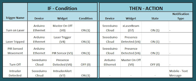
Now that all of the widgets have been added to the Dashboard, there is just one more step to complete the Security System. We need to setup the triggers. These triggers provide a level of automation that is easy to create within Cayenne, but would be very complicated otherwise. I set my triggers up as per the table below. Each row represents one of the triggers within my Cayenne dashboard. If you would like to see an example of how to add a trigger - please have a look at the video at the top of this tutorial.  


Concluding comments

I used many different elements to put this home/office security project together - Multiple Arduinos were connected to the internet, both controlled by a web/smart phone app, cross-communication/synchronisation between the Arduinos, and the use of multiple sensors and modules including a laser beam !
 
This was way more than just a simple PIR sense and alarm project. I now have a personalised greeting and reminder system when I walk in the door. Everyone else has their own personalised greeting. I can enable my Security System remotely, from two blocks away, and if I wanted to - I could enable it from the other side of the world. I know instantly when someone has entered my house/office.... with an SMS alert straight to my phone.
 
This project could easily be extended:

  1. Press a button on my phone to manually trigger/play a specific message/sound/song
  2. Take a picture of the intruder
  3. Introduce fire or leak detection aswell
  4. Add other environmental sensors - Temperature / Humidity
  5. Connect it to lamp/light - creating a security light
I am sure you can think of more things I could do with this system. In fact, why don't you mention your ideas in the comments below.
 
Cayenne was instrumental in getting this project to work. I don't think I would know where to start if I had to do this project without this cool IoT platform. I think I will definitely be trying out a few more projects using Cayenne, and should you want to do the same, then please make sure to join Cayenne Beta:
 
Here is the link you need to get to the right place: Cayenne Beta Link


If you like this page, please do me a favour and show your appreciation :

 
Visit my ArduinoBasics Google + page.
Follow me on Twitter by looking for ScottC @ArduinoBasics.
I can also be found on Pinterest and Instagram.
Have a look at my videos on my YouTube channel.


ScottC 02 Sep 05:11
alarm  arduino  arduinobasics  cayenne  laser  mp3  mydevices  pir  rfid  security  sms  tutorial  

Arduino based Security Project Using Cayenne


Description

This is an Arduino based home security project that uses the power of "Cayenne" for extraordinary capabilities.

Cayenne Beta

Cayenne is a new IoT drag and drop platform originally released for the Raspberry Pi, but now available for Arduino. Cayenne makes the task of connecting your Arduino to the internet as simple as possible. All of the complexity of internet connectivity is hidden within the Cayenne library.

You can easily create a Network of Arduinos and build an IoT system which can be managed and operated within the Cayenne dashboard. This dashboard is accessible through your browser or via the Cayenne smart phone app (on IOS or Android).

The feature I liked the most, was the ability to change the position of sensors or actuators on the Arduino without having to re-upload Arduino code. I could manage the changed position from within the Cayenne platform. The other feature that I liked was the ability to setup actions based on custom triggers. You can use Cayenne to trigger a whole range of functions, for example: play a sound, move a motor, light up an LED, or to send alert notifications via email or SMS.

Cayenne is in Beta at the moment, so there are a few minor bugs here and there, but overall - I give it a thumbs up - it is definitely worth checking out.
 

Here is a link to the Cayenne Beta Program:
**Cayenne Beta Link**


              Source: myDevices Media Kit


Home Security Project Summary

In order to fully experience this new IoT platform, I decided to create a project to really put it through its paces. This is what my Security Project will need:

  1. It will use two Arduinos, one connected to the internet via an Ethernet shield, and the other via WIFI.
  2. Two detectors - a PIR sensor and a laser trip wire.
  3. If the sensors are tripped, the person has 10 seconds to present an RFID tag to the Grove RFID reader:
    • If a valid RFID tag is SUCCESSFULLY presented within the time limit, a nice personalised greeting will be played to that person using a Grove - Serial MP3 player
    • If a valid RFID FAILS to be presented within the time limit, an Alarm will sound, and I will be notified of the intrusion via an SMS alert.
  4. The Cayenne dashboard will show the status of the sensors, and I will have full control over my security system via the web interface (or smartphone app).
  5. The sensors will be attached to a different Arduino to that of the Grove MP3 player and the RFID tag reader, which means that there will have to be some level of communication between the two Arduinos. In fact, the cross communication will be vital to the success of this project.


Project Video


Flow Diagrams:

Main Flow Diagram

The following flow diagram shows the Security project process. It is a high level view of the decisions being made by each Arduino in response to various events.  


Triggers Flow Diagram

The following flow diagram aims to highlight the various triggers set up within Cayenne to get this Security system to work.  


Arduino IDE and Library Downloads

You will need an Arduino IDE to upload code to the Arduino and the Seeeduino Cloud.
Here is the link to the Arduino IDE: Arduino IDE - download location

The Cayenne service requires that you download and install the Cayenne Library into your Arduino IDE.
You can get the Cayenne Library from here: Cayenne Library File - Download


Cayenne Connectivity Setup

The Seeeduino Cloud needs to be prepared for use with Cayenne.
Normal operating/setup instructions can be found here: Seeeduino Cloud WIKI page
 
Once you have successfully connected Seeeduino Cloud to your WIFI network, you can add it to the Cayenne Dashboard by making the following selections from within the Cayenne Web application:

  1. Add New
  2. Device/Widget
  3. Microcontrollers
  4. Arduino
  5. Ensure Seeeduino Cloud is connected to WIFI network - the select the NEXT button
  6. Select - Arduino Yun: Built-in Ethernet - ticked
  7. Providing you have already installed the Cayenne library as described above - you should be able to copy and paste the code to the Arduino IDE and upload to the Seeeduino Cloud.
  8. If successful, you should see the Arduino Yun board appear within the Cayenne Dashboard. If not, then seek help within the Cayenne forum.


The Arduino UNO with WIZNET 5100 - Ethernet Shield
also needs to be prepared with Cayenne

  1. Add New
  2. Device/Widget
  3. Microcontrollers
  4. Arduino
  5. Ensure Arduino is powered, and Ethernet shield is connected to your internet router via an Ethernet cable
  6. Select - Arduino Uno: Ethernet Shield W5100 - ticked
  7. Copy and paste the code to the Arduino IDE and upload to the Arduino UNO.
  8. If successful, you should see the Arduino Uno board appear within the Cayenne Dashboard. If not, then seek help within the Cayenne forum.


If you have the Ethernet shield with the WIZNET 5200 chip, then you may need to download a specific Ethernet library in addition to the Cayenne library.
 
Just follow the instructions within the Automatically generated sketch provided - when you select your specific Arduino/Ethernet/WIFI shield combination. If you need further instructions on connecting your device to Cayenne - then please visit the myDevices website for the online documentation.


ARDUINO CODE (1)


Code for Arduino UNO with Ethernet Shield:

The following code will need to be uploaded to the Arduino UNO:


ARDUINO CODE (2)


Code for Seeeduino Cloud:

The following code will need to be uploaded to the Seeeduino Cloud:


Fritzing diagram (1)


Fritzing diagram for Arduino UNO with Ethernet

Please click on the picture below for an enlarged version of this fritzing diagram


Fritzing diagram (2)


Fritzing diagram for Seeeduino Cloud

Please click on the picture below for an enlarged version of this fritzing diagram


Cayenne Dashboard Setup - GUI


The Arduino code only provides half of the functionality of this project. The Cayenne Dashboard needs to be setup to provide the rest of the functionality. The following instructions will show you how to add each of the widgets required for this Home Security project.


Arduino Ethernet - Master Switch

The master switch allows me to turn the security system on and off. When I turn the MASTER SWITCH ON, the laser beam will turn on, and the sensors will start monitoring the area for intruders. This widget is NOT associated with a physical switch/sensor on the Arduino - it uses virtual channel 0. We need to add the Master switch to the dashboard:


  1. Add New
  2. Device/Widget
  3. Actuators
  4. Generic
  5. Digital Output - Control a Digital Output
  6. Widget Name: Master On Off Switch
  7. Select Device: Arduino Ethernet
  8. Connectivity: Virtual
  9. Pin: V0
  10. Choose Widget: Button
  11. Choose Icon: Valve
  12. Step2: Add Actuator
We will add a trigger later to get this button to automatically turn the Laser beam on.


Arduino Ethernet - PIR Sensor

This sensor will be used to detect movement in the room. If a person walks into the room, this sensor will detect movement, and will trigger a message to be played on the Grove Serial MP3 player. The message will aim to get the person to identify themselves. They identify themselves by placing their RFID tag in close proximity to the Grove RFID reader. If the tag is valid, a "Welcome home" message is played on the Grove MP3 player. If a valid tag is not presented to the reader within 10 seconds, an Alarm will go off ("Alarm sound" played on Grove MP3 player.)

The PIR sensor is connected to digital Pin 6 of the Arduino, however, it is mapped to virtual pin 1 for better synchronisation with the Cayenne dashboard. This was done to capture ALL detections - as the PIR sensor could change from a LOW to HIGH and back to LOW state in between a Cayenne state check - and therefore, Cayenne could miss this motion detection.. Therefore we need to assign the PIR sensor to a virtual channel in the following way:
  1. Add New
  2. Device/Widget
  3. Sensors
  4. Motion
  5. Digital Motion Sensor - Motion Detector
  6. Widget Name: PIR sensor
  7. Select Device: Arduino Ethernet
  8. Connectivity: Virtual
  9. Pin: V1
  10. Choose Widget: 2-State Display
  11. Choose Icon: Light
  12. Step2: Add Sensor
  13. Select Settings from the PhotoResistor
  14. Choose Display: Value
  15. Save


Arduino Ethernet - Photoresistor

This sensor will be used with the laser beam to create a laser tripwire. If the sensor detects a change in light levels (drops below the threshold), it will activate the laser trigger button on the dashboard. The person will then be required to identify themselves etc etc (similar to the motion detection by the PIR sensor). The photoresistor widget will display the raw analog reading from the sensor (connected to A2), but is associated with virtual channel 2. I used a virtual channel for more control over this sensor. To add the Photoresistor to the dashboard:

  1. Add New
  2. Device/Widget
  3. Sensors
  4. Luminosity
  5. Photoresistor - Luminosity sensor
  6. Widget Name: PhotoResistor
  7. Select Device: Arduino Ethernet
  8. Connectivity: Virtual
  9. Pin: V2
  10. Choose Widget: Value
  11. Choose Icon: Light
  12. Step2: Add Sensor


Arduino Ethernet - Laser Trigger

The laser trigger is just an indicator that someone tripped the laser beam. The state of this widget is used to notify the Seeeduino that a presence has been detected. This widget is associated with virtual pin 4 on the Arduino UNO with Ethernet.

  1. Add New
  2. Device/Widget
  3. Actuators
  4. Generic
  5. Digital Output - Control a Digital Output
  6. Widget Name: Laser Trigger
  7. Select Device: Arduino Ethernet
  8. Connectivity: Virtual
  9. Pin: V4
  10. Choose Widget: Button
  11. Choose Icon: Lock
  12. Step2: Add Actuator


Arduino Ethernet - Laser Threshold

The laser threshold is used to manually configure the light level at which the laser trigger will trip. When the photoresistor value drops below the threshold value, the laser trigger icon will activate. This allows the threshold value to be updated from the Cayenne dashboard, rather than having to manually adjust the value in the Arduino code. Also, this threshold can be set remotely, in that you don't have to be near the Arduino to change this value. A very useful feature of this Security system. This widget is associated with virtual pin 5 on the Arduino UNO with Ethernet.

  1. Add New
  2. Device/Widget
  3. Actuators
  4. Generic
  5. PWM Output - Control a PWM Output
  6. Widget Name: Laser Threshold
  7. Select Device: Arduino Ethernet
  8. Connectivity: Virtual
  9. Pin: V5
  10. Choose Widget: Slider
  11. Slider Min Value: 0
  12. Slider Max Value: 10
  13. Step2: Add Actuator
The max value of the slider is 10 - due to a current bug in the Cayenne software. Once resolved, this value (as well as the relevant Arduino code) will need to be updated.


Seeeduino Cloud - Presence Detected

The presence detected widget is there to notify the Seeeduino Cloud that a presence has been detected on the Arduino Uno with Ethernet shield. When the PIR sensor detects movement or if the laser tripwire is tripped, Cayenne will change the state of the Presence Detected widget from LOW to HIGH. This is used within the Seeeduino Cloud to trigger the message "Place your keys on the Mat"
. If a valid RFID tag is read by the Grove RFID reader, then this widget's state will change back from HIGH to LOW, and the MasterSwitch will be deactivated - turning the Security system off. This widget is associated with Virtual pin 6 on the Seeeduino Cloud.

  1. Add New
  2. Device/Widget
  3. Actuators
  4. Generic
  5. Digital Output - Control a Digital Output
  6. Widget Name: Presence Detected
  7. Select Device: Seeeduino Cloud
  8. Connectivity: Virtual
  9. Pin: V6
  10. Choose Widget: Button
  11. Choose Icon: Lock
  12. Step2: Add Actuator


Seeeduino Cloud - Intruder Alert

If a valid RFID tag is not read by the Grove RFID reader within 10 seconds of a presence detection event, an alarm will sound, and this widget will be activated. This will trigger a notification event - to notify me of the unauthorised intrusion - via SMS or email. I will also have a visual indicator on the Cayenne dashboard that an intrusion has taken place. This widget is associated with Virtual pin 7 on the Seeeduino Cloud.

  1. Add New
  2. Device/Widget
  3. Actuators
  4. Generic
  5. Digital Output - Control a Digital Output
  6. Widget Name: Laser Trigger
  7. Select Device: Seeeduino Cloud
  8. Connectivity: Virtual
  9. Pin: V7
  10. Choose Widget: Button
  11. Choose Icon: Thermometer
  12. Step2: Add Actuator


Seeeduino Cloud - Laser Beam

The laser beam widget was created to allow for full control over the laser beam. The laser beam can be turned on or off from the Cayenne dashboard, and a connected to digital pin 7 on the Seeeduino Cloud.


  1. Add New
  2. Device/Widget
  3. Actuators
  4. Light
  5. Light Switch - Turn On/Off a Light
  6. Widget Name: xLaser Beam
  7. Select Device: Seeeduino Cloud
  8. Connectivity: Digital
  9. Pin: D7
  10. Choose Widget: Button
  11. Choose Icon: Light
  12. Step2: Add Actuator


Cayenne Triggers

Now that all of the widgets have been added to the Dashboard, there is just one more step to complete the Security System. We need to setup the triggers. These triggers provide a level of automation that is easy to create within Cayenne, but would be very complicated otherwise. I set my triggers up as per the table below. Each row represents one of the triggers within my Cayenne dashboard. If you would like to see an example of how to add a trigger - please have a look at the video at the top of this tutorial.  


Concluding comments

I used many different elements to put this home/office security project together - Multiple Arduinos were connected to the internet, both controlled by a web/smart phone app, cross-communication/synchronisation between the Arduinos, and the use of multiple sensors and modules including a laser beam !
 
This was way more than just a simple PIR sense and alarm project. I now have a personalised greeting and reminder system when I walk in the door. Everyone else has their own personalised greeting. I can enable my Security System remotely, from two blocks away, and if I wanted to - I could enable it from the other side of the world. I know instantly when someone has entered my house/office.... with an SMS alert straight to my phone.
 
This project could easily be extended:

  1. Press a button on my phone to manually trigger/play a specific message/sound/song
  2. Take a picture of the intruder
  3. Introduce fire or leak detection aswell
  4. Add other environmental sensors - Temperature / Humidity
  5. Connect it to lamp/light - creating a security light
I am sure you can think of more things I could do with this system. In fact, why don't you mention your ideas in the comments below.
 
Cayenne was instrumental in getting this project to work. I don't think I would know where to start if I had to do this project without this cool IoT platform. I think I will definitely be trying out a few more projects using Cayenne, and should you want to do the same, then please make sure to join Cayenne Beta:
 
Here is the link you need to get to the right place: Cayenne Beta Link


If you like this page, please do me a favour and show your appreciation :

 
Visit my ArduinoBasics Google + page.
Follow me on Twitter by looking for ScottC @ArduinoBasics.
I can also be found on Pinterest and Instagram.
Have a look at my videos on my YouTube channel.


ScottC 30 Aug 15:42
alarm  arduino  arduinobasics  cayenne  laser  mp3  mydevices  pir  rfid  security  sms  tutorial  

Interfacing SIM900 with arduino uno

In this post, we will learn how to interface SIM900 with arduino uno.

First of all, insert sim in sim socket of GSM module. Power it up by 12V 2A dc adapter.

Now, we have to make connections as follows:

Arduino Side                       GSM module
Tx                =====>          Rx
Rx                =====>          Tx
GND            =====>          GND

The source code is given below:

    boolean bOK = HIGH;

    void setup()
    {
    Serial.begin(4800);
    delay(1200);
    }
    void loop()
    {
 
    if(bOK==1)
    {
    Serial.println("AT+CMGF=1"); // sets the SMS mode to text
    delay(1500);
    Serial.print("AT+CMGS=\""); // send the SMS number
    Serial.print("+9199XXXXXXXX"); // +91 for india
    Serial.println("\"");
    delay(1000);
    Serial.print("Hello World "); // SMS body
    delay(500);

    Serial.write(0x1A);
    Serial.write(0x0D);
    Serial.write(0x0A);
    bOK=LOW;
    }
    }

The source code is self-explanatory.

Thanks for visiting this blog.

Stay tuned for more projects !!

FunWithElectronics 02 May 20:44
arduino uno  sim 900  sms  

Testing a Heart Pulse Alarm based on Arduino Uno

Murad is a student of Mechatronics and Engineering at Tafila Technical University in the town of Tafila, in Jordan. He made a submission to our blog presenting his DIY project of a Heart Pulse Alarm based on Arduino Uno.

The HPA (Heart Pulse Alarm) is a portable device prototyped to measure the pulse rate and the body temperature of who’s wearing it. If the device receives an unusual heart pulse, it will send a sms message to paramedics to act quickly. He designed the device to help people who have cardiac problems and they lack  the resources for personal and professional assistants in his country.

Check the bill of materials and code on his blog.


Arduino Blog 18 Nov 16:59
arduino  arduino uno  diy  featured  gps  heart-beat  sms  uno  

A Nokia Shield For The Arduino

The Nokia 3100 is a classic in the circles we frequent. The LCD in this phone is a very cheap and very common display, and it was one of the most popular phones since the phone from Bell, making it a very popular source of cool components.

Now everything is an Internet of Thing, and cellular data for microcontroller projects is all the rage. [Charles] thought it would be interesting to use the famous Nokia 3100 to transmit and receive data. After battling with some weird connectors, he succeeded.

The Nokia 3100 doesn’t have a USB connector, as this phone was made before the EU saved us from a menagerie of cell phone chargers. Instead, this phone has a Nokia Pop-Port, a complex connector that still has TX and RX pins running at 115,200 bit/s 8N1. By fitting a USB socket onto a prototyping board, adding a few level shifters, and connecting the pins in the right order, [Charles] was able to get his Arduino talking to an old Nokia Brick.

[Charles] isn’t quite at the level of sending SMS from his confabulation, and even following a tutorial from [Ilias Giechaskiel] didn’t work. [Charles] is looking for help here, and if you have any suggestions, your input would be appreciated.

There is a problem with using a Nokia 3100 as a cheap Arduino cellular shield: it’s only 2G, and sometime soon those cell towers will be shut down. For now, though, it works, and once those 2G towers are shut down, there are plenty of options with cheap, early Android and iOS phones.


Filed under: Arduino Hacks, Cellphone Hacks

Adding WiFi and SMS to an Alarm System

[Don] wanted to bring his alarm system into the modern age. He figured that making it more connected would do the trick. Specifically, he wanted his alarm system to send him an SMS message whenever the alarm was tripped.

[Don] first had to figure out a way to trigger an event when the alarm sounds. He found a screw terminal that lead to the siren. When the alarm is tripped, this screw terminal outputs 12V to enable the siren. This would be a good place to monitor for an alarm trip.

[Don] is using an Arduino nano to monitor the alarm signal. This meant that the 12V signal needed to be stepped down. He ran it through a resistor and a Zener diode to lower the voltage to something the Arduino can handle. Once the Arduino detects a signal, it uses an ESP8266 WiFi module to send an email. The address [Don] used is the email-to-SMS address which results in a text message hitting his phone over the cell network.

The Arduino also needed power. [Don] found a screw terminal on the alarm system circuit board that provided a regulated 12V output. He ran this to another power regulator board to lower the voltage to a steady 5V. This provides just the amount of juice the Arduino needs to run, and it doesn’t rely on batteries. [Don] provides a good explanation of the system in the video below.


Filed under: Android Hacks, security hacks
Hack a Day 17 Jan 00:01

Controlling Nokia Phones with Arduino

While [Ilias Giechaskiel] was waiting for his SIM900 shield to arrive, he decided to see what he could do with an old Nokia 6310i and an Arduino. He was researching how to send automated SMS text messages for a home security project, and found it was possible to send AT commands via the headphone jack of Motorola phones. But unfortunately Nokia did not support this, as they use a protocol know as FBus. With little information to go on, [Ilias] was able to break down the complicated protocol and take control with his Arduino.

With the connections were in place, [Ilias] communicated with the Nokia phone using a program called Gnokii — a utility written specifically for controlling the phone with a computer. Using the Arduino as an intermediary, he was eventually able tap into the FBus and send SMS messages.

Be sure to check out his blog as [Ilias] goes into great detail on how Nokia’s FBus protocol works, and provides all source code needed to replicate his hack. There is also a video demonstration at the end showing the hack in action.


Filed under: Arduino Hacks, Cellphone Hacks

Laundry Text Message Alerts With Arduino Yun

The buzzer on a washer or dryer may be OK for most people, but what if you would like something a little more versatile to tell you when your laundry is done? Here’s an interesting solution involving an Arduino Yún that sends a text message when the washer or dryer […]

Read more on MAKE

MAKE » Arduino 15 Dec 13:01
arduino  home  laundry  sms  text message