Description
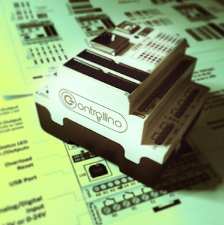
This tutorial will show you how to take over the controls of the OWI Robotic Arm with the help of an Arduino compatible, open-source PLC called the Controllino MAXI, together with Cayenne (my go-to iOT application for remote connection to my Arduino projects). The Controllino MAXI will provide the physical connections to the OWI robotic arm, and Cayenne will allow me to control the arm via my web browser or via the Cayenne app on my phone.
Arduino Libraries and IDE
- The Arduino IDE can be used to program the Controllino. You can dowload the Arduino IDE from here: https://www.arduino.cc/en/main/software.
- You will also need to read the Cayenne Ethernet library installation instructions in order to install the Cayenne Ethernet Library.
- The Controllino will connect to the internet via the Ethernet port onboard.
- You do not need the Controllino library for this project, however, if you have a Controllino, you might as well install the library. You can read the Controllino library installation instructions from their GitHub webpage here: https://github.com/CONTROLLINO-PLC/CONTROLLINO_Library.
- You will need to notify the Arduino IDE of the Controllino MAXI board by pasting the supplied URL into the "Additional Boards Manager URLs" in the Arduino IDE.
- This is located under: FILE - PREFERENCES - Additional Boards Manager URLs.
- The URL that you need to paste is in STEP 3 of the Controllino Library installation instructions on their GitHub page.
- The video at the top of this tutorial may help clarify the process.
The code above is very simple, however you will need to create a dashboard of widgets from within your Cayenne account in order to control the OWI robotic Arm from your phone or via the Dashboard webpage.
Setting up Cayenne Dashboard
Once you have created your Cayenne account, you will be presented with a webpage to choose a board to connect to. Controllino is an Arduino compatible PLC, so make sure to follow these instructions for setting up the Controllino in your Cayenne Account.
- Select Arduino from the available list of boards.
- Make sure to install the necessary libraries if your have not done so already.
- Select Arduino MEGA from the avaliable list of Arduino boards
- Select Ethernet Shield W5100
- Copy and paste the Arduino code that pops up on screen into your Arduino IDE and upload to the Controllino.
- Alternatively, copy and paste the code from above, however you will need to insert your Authentication token to get it to work
After you upload the code to the Controllino, and providing it has an ethernet cable connected to the internet router (and has access to the internet), and is powered on, it will connect to your Cayenne Dashboard. You can now add widgets to the dashboard in real time to interact with the Controllino, and without uploading any more code to the open source PLC.
Adding Widgets
We need to add a number of widgets in order to activate the relays on the Controllino. The relavent digital pins that we will need to know about can be found on the Controllino website here: https://controllino.biz/downloads/.
Here is the direct link to the PINOUT file for the Controllino MAXI.
"Armed" with that knowledge, we can now create the widgets which are necessary to control the relays on the Controllino. From within the Cayenne dashboard, please follow these instructions to create a widget:
- Select - ADD NEW
- Select - DEVICE/WIDGET
- Select - ACTUATORS
- Then - RELAY from the dropdown box
- Select - RELAY SWITCH
- Give the widget a descriptive name to differentiate it from the other widgets and a name that is somewhat informative (eg. R0 - Pos)
- I gave the first widget the name "R0 - Pos", because it will connect to Relay R0, and that relay will be connected to the Positive (POS) terminal of the OWI robotic arm.
- Select the device you would like to connect to. Be aware that you can change the name of the device in the settings. If you followed this tutorial, it should have the name "Arduino MEGA", but I changed the name of the device to "Controllino" to be more accurate.
- We will be using a digital pin to control the relay, therefore select "Digital" as the Connectivity option
- For this specific widget, we will be controlling R0, which is activated by digital pin D22 on the Controllino. Therefore select "D22" from the "Pin" dropdown box.
- Choose a "Button" as the widget type
- Choose an icon from the dropdown box that makes sense to you
- Skip Step 1
- Select Step 2: Add actuator
You should now see your new widget on the dashboard. Select the widget to enable or activate that relay. If you do this, and if everything goes to plan, you will see the LED for R0 illuminate on the Controllino. You now have to add the rest of the widgets to the dashboard in order to control the rest of the relays on the Controllino.
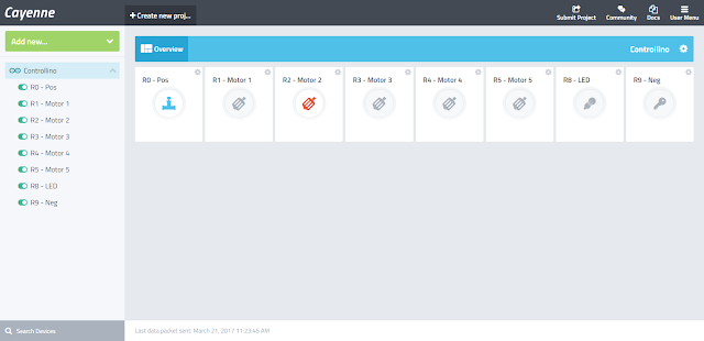
Widget Dashboard
Here is a table to show you how I setup my dashboard.

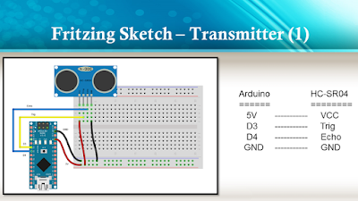
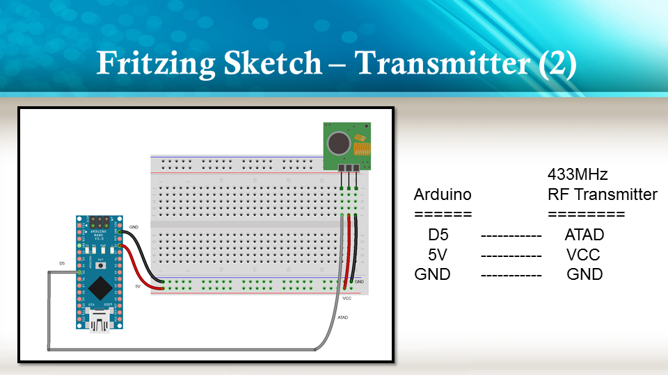
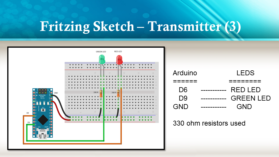
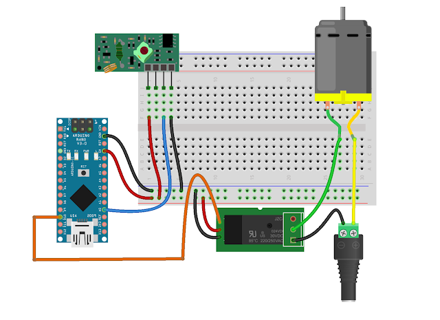
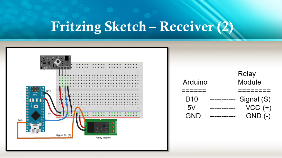
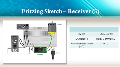
Fritzing diagram
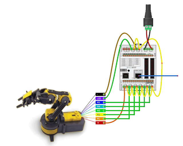
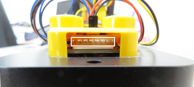
OWI Robotic Arm Pins

Normal OWI Robotic Arm Circuit
The following circuit diagram will show you how the wired control box is normally connected to the OWI Robotic arm. This is the circuit diagram of the OWI robotic arm under normal operating contidtions.

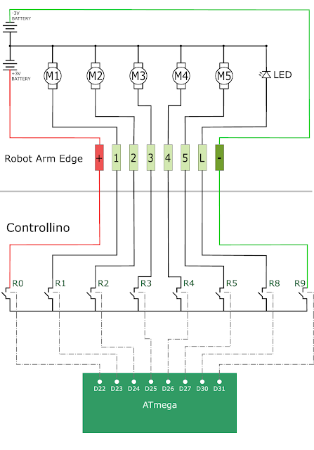
OWI Robotic Arm Circuit when connected to Controllino
The following circuit diagram will show you how the OWI Robotic Arm will be controlled by the relays of the Controllino. This is the circuit diagram of the OWI robotic arm when it is connected to the Controllino.
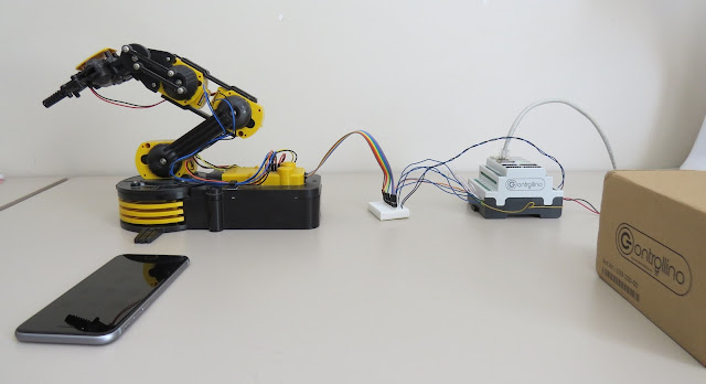
All connected
The OWI Robotic Arm is connected to a breadboard using the female-to-male jumper wires. Solid core wire is then fed through to the relay terminals of the Controllino. You could just wire it up so that the robotic arm is connected directly to the Controllino, however, I did not have the right connectors for this purpose.
The Controllino is also connected to my internet router via a normal RJ-45 ethernet cable, and is powered by a 12V DC power adapter.
Summary
Now that you have all the physical connections made, uploaded the code to the Controllino, and have created your dashboard in Cayenne, you should be able to control your OWI Robotic arm from anywhere in the world. As demonstrated in the video at the start of this tutorial, the robotic arm has quite a bit of give on each of the joints, which makes it difficult to achieve certain tasks that require an element of precision. There goes that idea of being able to perform surgery with this thing !!! At least you can get it to make you a cup of tea, and if you are patient enough, you might even get a grape once in a while.
Thank you to Controllino and Cayenne for making this tutorial possible. If you would like your product featured in my tutorials, please contact me on my contact page.