Posts with «temperature sensor» label

An Epic Tale of Thermistors: Tricks for Much Better Temperature Sensing

For years [Edward] has been building professional grade underwater sensing nodes at prices approachable for an interested individual without a government grant. An important component of these is temperature, and he has been on a quest to get the highest accuracy temperature readings from whatever parts hit that sweet optimum between cost and complexity. First there were traditional temperature sensor ICs, but after deploying numerous nodes [Edward] was running into the limit of their accuracy. Could he use clever code and circuitry to get better results? The short answer is yes, but the long answer is a many part series of posts starting in 2016 detailing [Edward]’s exploration to get there.
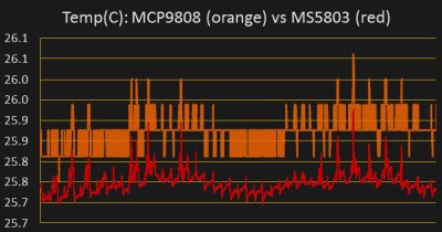
Orange is 12 bits, red is 24

The first step is a thermistor, a conceptually simple device: resistance varies with temperature (seriously, how much more simple can a sensor get?). You can measure them by tapping the center of a voltage divider the same way you’d measure any other resistance, but [Edward] had discarded this idea because the naive approach combined with his Arduino’s 10 bit ADC yielded resolution too poor to be worthwhile for his needs. But by using the right analog reference voltage and adjusting the voltage divider he could get a 20x improvement in resolution, down to 0.05°C in the relevant temperature range. This and more is the subject of the first post.

What comes next? Oversampling. Apparently fueled by a project featured on Hackaday back in 2015 [Edward] embarked on a journey to applying it to his thermistor problem. To quote [Edward] directly, to get “n extra bits of resolution, you need to read the ADC four to the power of n times”. Three bits gives about an order of magnitude better resolution. This effectively lets you resolve signals smaller than a single sample but only if there is some jitter in the signal you’re measuring. Reading the same analog line with no perturbation gives no benefit. The rest of the post deals with the process of artificially perturbing the signal, which turns out to be significantly complex, but the result is roughly 16 bit accuracy from a 10 bit ADC!

What’s the upside? High quality sensor readings from a few passives and a cheap Arduino. If that’s your jam check out this excellent series when designing your next sensing project!

The No-Parts Temperature Sensor In Your Arduino

[Edward], creator of the Cave Pearl project, an underwater data logger, needed a way to measure temperature with a microcontroller. Normally, this problem is most easily solved by throwing a temperature sensor on the I2C bus — these sensors are cheap and readily available. This isn’t about connecting a temperature sensor in your Arduino. This build is about using the temperature sensor in your clock.

The ATMega328p, the chip at the heart of all your Arduino Uno clones, has within it a watchdog timer that clicks over at a rate of 110 kHz. This watchdog timer is somewhat sensitive to temperature, and by measuring this temperature sensor you can get some idea of the temperature of the epoxy blob that is a modern microcontroller. The trick is calibrating the watchdog timer, which was done with a homemade ‘calibration box’ in a freezer consisting of two very heavy ceramic pots with a bag of rice between them to add thermal mass (you can’t do this with water because you’re putting it in a freezer and antique crocks are somewhat valuable).

By repeatedly taking the microcontroller through a couple of freeze-thaw cycles, [Edward] was able to calibrate this watchdog timer to a resolution of about 0.0025°C, which is more than enough for just about any sensor application. Discussions of accuracy and precision notwithstanding, it’s pretty good.

This technique measures the temperature of the microcontroller with an accuracy of 0.005°C or better, and it’s using it with just the interrupt timer. That’s not to say this is the only way to measure the temperature of an ATMega; some of these chips have temperature sensors built right into them, and we’ve seen projects that use this before. However, this documented feature that’s clearly in the datasheet seems not to be used by many people.

Thanks [jan] for sending this in.

Gesture Sensing With A Temperature Sensor

Good science fiction has sound scientific fact behind it and when Tony Stark first made his debut on the big screen with design tools that worked at the wave of a hand, makers and hackers were not far behind with DIY solutions. Over the years the ideas have become much more polished, as we can see with this Gesture Recognition with PIR sensors project.

The project uses the TPA81 8-pixel thermopile array which detects the change in heat levels from 8 adjacent points. An Arduino reads these temperature points over I2C and then a simple thresholding function is used to detect the movement of the fingers. These movements are then used to do a number of things including turn the volume up or down as shown in the image alongside.

The brilliant part is that the TPA81 8-Pixel sensor has been around for a number of years. It is a bit expensive though it has the ability to detect small thermal variations such as candle flames at up to 2 Meters. More recent parts such as the Panasonic AMG8834 that contain a grid of 8×8 such sensors are much more capable for your hacking/making pleasure, but come with an increased price tag.

This technique is not just limited to gestures, and can be used in Heat-Seeking Robots that can very well be trained to follow the cat around just to annoy it.

Temperature based fan speed control using arduino uno and lm35

In this post, we will make a temperature based fan control using arduino and lm35. LM35 is temperature sensor, whose output is analog (linear). Arduino uno has six channle of adc (A0-A5)
and adc is of 10-bit

Stuff required:
  • Arduino UNO
  • LM35
  • LCD 16*2
  • POT 10k
  • Motor driver (L293D)
  • DC motor

Circuit Diagram

Resolution = Vref/((2^n)-1)  = 5000 (in mV)/1023   [2^10-1]

that comes out to be, 4.887 millivolts

For temperature calculation, Voltage (in millivolts)/10    [Sensitivity is 10mV per degree Celsius]

Source Code:

Download source code from link below


Watch the Video:


Temperature on GUI using visual studio and arduino

In this post, first we will interface LM35 with arduino uno and then  upload this data through serial communication. With the help of visual studio we can make computer gui application and though this gui application, we can do lot of stuffs like temperature logger, humidity monitoring. The

Stuff we require:

  1. Arduino uno with usb cable
  2. LM35
  3. Jumper wires
  4. Visual Studio (I had used VS 2012)
Make connections as follows:

LM35 interfacing with arduino


Simply provide, Vcc and GND to temperature sensor (LM35) and it's output should be connected to A0 of arduino. You can connect it to any channel from A0 to A5.

Calculation part:

There is little bit calculation. LM35 gives analog output. It's linearity is 10 mV/°C
which literally means for rise in temperature of 1°C, there be an increment of mV from output of lm35. It's graph is linear. It's temperature range is from: -55°C to +150°C.
Since, we are using LM35 it is calibrated in terms of degree celsius. There are other variants available like lm235 and lm335.

Arduino Code: 

The code is very simple

/*
Code Starts
*/


float val=0.0;

void setup() {
Serial.begin(9600);
}

void loop() 
{
val=analogRead(A0);
val=(0.4887*val);
Serial.println("VALUE OF TEMPERATURE IS: " + String(val) );
delay(1500);
}

/*
Code Ends
*/

Check out the video:


Visit this blog for more updates !!


Temperature updation on thingspeak using sim900

Hello friends,

In this post we are going to discuss how to upload temperature on thingspeak channel using sim 900 and arduino uno. As I had already uploaded the data on thingspeak channel using sim 900 and terminal software.

Introduction:

This project is a wireless temperature logger on thingspeak channel using gsm module and arduino.
For temperature sensor, we are using lm35, that gives output in millivolt which can be easily calibrated in  terms of  °C. We have to use adc module, since it's an analog sensor. Once the raw data is converted into temperature, we can upload the data.

Now, we are ready to upload the data on thingspeak channel. Thingspeak provides api for uploading of data. Before this, we have to use activate GPRS on sim900. We also to provide APN for accessing the internet. After activating the GPRS, we have to use GET like this:

GET http://api.thingspeak.com/update?api_key=QZFXXXXXXXXXXX&field1=data

Replace this api with yours, and data is the data you want to be upload. You can upload a number of field like temperature, pressure, humidity, etc.
 

Stuff you need:

  1. SIM900A
  2. Arduino uno
  3. LM35 (it's output is in degree celsius)
  4. 12 volt adapter (for GSM module)
  5. Jumper wires
  6. Account on thingspeak


Connections:

Arduino                              GSM module
Pin no. 7     ======>         Tx
Pin no. 8     ======>         Rx
Gnd            ======>          Gnd

Output of LM35 is connected to A0 of arduino uno.


Download the code from here:


Arduino Replaces Bad AC Thermostat, Hacker Stays Cool

Most of North America has been locked in a record-setting heat wave for the last two weeks, and cheap window AC units are flying out of the local big-box stores. Not all of these discount units undergo rigorous QC before sailing across the Pacific, though, and a few wonky thermostats are sure to get through. But with a little sweat-equity you can fix it with this Arduino thermostat and temperature display.

We’ll stipulate that an Arduino may be overkill for this application and that microcontrollers don’t belong in every project. But if it’s what you’ve got on hand, and you’re sick of waking up in a pool of sweat, then it’s a perfectly acceptable solution. It looks like [Engineering Nonsense] got lucky and had a unit with a low-current power switch, allowing him to use a small relay to control the AC. The control algorithm is simple enough – accept a setpoint from an encoder, read the temperature sensor, and turn the AC on or off accordingly. Setpoint and current temperature are displayed on an OLED screen. One improvement we’d suggest is adding a three-minute delay between power cycles like the faceplate of the AC states.

This project bears some resemblance to this Arduino-controlled AC, but it seems more hackish to us. And that’s a good thing – hackers have to keep cool somehow.


Filed under: Arduino Hacks, home hacks

Temperature controlled dc fan

In this post, we will control the speed of dc fan based on the temperature.

List of components:

1. Arduino Uno
2. LM 35 temperature sensor
3. LCD 16*2
4. 10k potentiometer
5. ULN 2003
6. DC motor
7. Breadboard/ perfboard

First of all, we will monitor the temperature by using lm35 i.e. temperature sensor. It's scale factor is +10mV/°C which means with increment in temperature by 1° Celsius, the voltage is rise by 10 mV.
We can read adc count by analogRead(A0); // we are using channel A0

This will give us a digital count of adc which varies from 0 to 1023, we have to convert these count into voltage and then into temperature. First of all, we will convert into voltage:
In arduino uno, adc is of 10-bit.
Resolution = Vref/(2^n-1), where n is bit (in our case it's 10)
Resolution = 5000 / 1023, ( Verf = 5000 mV and 2^10 is 1024 minus 1 is 1023)

Resolution = 4.887 mV
Now, we have to convert voltage into temperature:
Temperature (in °C) = Voltage (in mV) / 10.0
With this temperature monitoring is over.

LCD interfacing is simple since we have library for the same with proper documentation.

Now coming to pwm part. In arduino, we can control output voltage by pulse width modulation (pwm).
Duty Cycle = Ton / (Ton + Toff)
Duty Cycle = Ton / T

Duty Cycle (in %age) = (Ton / T)*100

In arduino, for pwm we have analogWrite function :

In arduino uno, we have six pwm channels viz, pin no. 3, 5, 6, 9, 10 and 11.

analogWrite(pin no, value)

Pin no may be 3, 5, 6, 9, 10 and 11
Value varies from 0 to 255 since pwm resolution is of 8-bit (2^8-1)

0 for 0% duty cycle                  0 volts
64 for 25% duty cycle              1.25 volts            if(val<=40.0)
127 for 50% duty cycle            2.50 volts            if(val>40.0 && val<=50.0)
192 for 75% duty cycle            3.75 volts            if(val>50.0 && val<=60.0)
255 for 100% duty cycle          5.00 volts            if(val>60.0)

where val is temperature in °C

Vavg = Duty Cycle  * 5.0 volts
 
Schematic of temperature controlled fan
Download the source code from the link below:


Stay tuned for more updates !!


Interfacing temperature sensor with arduino

Interfacing temperature sensor (LM35) with arduino:

In this post, we will learn how to interface temperature sensor (LM35) with arduino uno.

Arduino Uno is an open-source electronic prototype board used by beginners, hobbyists and developers across the globe, Arduino have so many forums, if you need any help, guidance.
Arduino uno is based on atmega 328p microcontroller. Arduino uno comes in two pckages:
Through-hole package and SMD package.

For the time being, we are considering through-hole package. It's a 28-pin DIP (dual inline package) IC.  There are 14-digital I/O pins and 6-analog input pins.
Arduino has a rich library support. For example: led blinking, lcd interfacing, etc. all these program can br found in library.

In order to display data received from temperature esnsor, we need display device like seven segment display or lcd or alternatively we can use serial monitor.

LM-35 is a temperature sensor. It's sensitivity is 10mV/°C which literally means with rise in temperature by 1° Celsius the voltage is increased by 1 millivolts. It's graph is linear.
It's range is from -55° Celsius to +150° Celsius.

Arduino have 6-adc channels viz, A0-A5. These are 10-bit adc means 0-5 analog volt is converted into digital count ranging from 0-1023

Resolution = Vref/((2^10)-1) = Vref/1023

We are taking Vref as 5 volt. Now, the resolution comes out to be 4.887 mV

In order to convert digital count into voltage, we have to multiply it by 4.887. Now we have voltage. We have to convert this voltage into temperature. This is known as calibration.

Temperature in ° C = 4.887 * digital count (0-1023) /10.0

Here are the screenshots of prteus simulation and code:

Proteus simulation


Download arduino code and simulation from the link given below:

https://drive.google.com/file/d/0B4Px6Drl6Zz_RFB2MEM4YUdPRGM/view?usp=sharing

Stay tuned for more updates !!


New Project: Wearable Temperature Sensors For Working in Extreme Cold

When working in extreme temperatures it is important to monitor your body temperature. In freezing weather, your fingers and toes get numb and you can develop frostbite without even noticing it. Likewise, if your core body temperature drops too low, you can start to start to suffer the effects of […]

Read more on MAKE