Posts with «adc resolution» label

Arduino Measures 20V Signals Using Quantizer
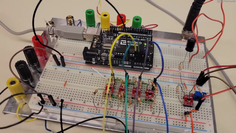
Canadian electronics geek and nascent YouTuber [Technoyaki] wanted to measure 20 volt signals on his Arduino. One might typically use a voltage divider to knock them down to the 5 volt range of the Arduino’s 10-bit A/Ds. But he isn’t one to take the conventional approach. Instead of using two resistors, [Technoyaki] decides to build an analog circuit out of sixteen resistors, four op amps and a separate 6 VDC supply.
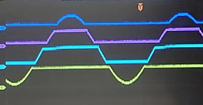
What is a quantizer? In the usual sense, a quantizer transforms an analog signal (with an infinity of possible values) to a smaller (and finite) set of digital values. An A/D converter is a perfect example of a quantizer. [Technoyaki], stretching the definition slightly, and uses the term to describe his circuit, which is basically a voltage slicer. It breaks up the 20 V signal into four separate 5 V bands. Of course, one could almost  accomplish this by just using an Arduino Due, which has a 12-bit A/D converter (almost, because it has a lower reference voltage of 3.3 V). But that wouldn’t be as much fun.

Why use all these extra components? Clearly, reducing parts count and circuit complexity was not one of [Technoyaki]’s goals. As he describes it, the reason is to avoid the loss of A/D resolution inherent with the traditional voltage divider. As a matter of semantics, we’d like to point out that no bits of resolution are lost when using a divider — it’s more accurate to say that you gain bits of resolution when using a circuit like the quantizer.  And not surprising for precision analog circuitry, [Technoyaki] notes that there are yet a few issues yet to be solved. Even if this circuit ultimately proves impractical, it’s a neat concept to explore. Check out the video below the break, where he does a great job explaining the design and his experiments.

Even though this isn’t quite a cut-and-paste circuit solution at present, it does show another way to handle large signals and pick up some bits of resolution at the same time. We wrote before about similar methods for doubling the A/D resolution of the Arduino. Let us know if you have any techniques for measuring higher voltages and/or increasing the resolution of your A/D converters.

Hack a Day 03 Sep 21:00

An Epic Tale of Thermistors: Tricks for Much Better Temperature Sensing

For years [Edward] has been building professional grade underwater sensing nodes at prices approachable for an interested individual without a government grant. An important component of these is temperature, and he has been on a quest to get the highest accuracy temperature readings from whatever parts hit that sweet optimum between cost and complexity. First there were traditional temperature sensor ICs, but after deploying numerous nodes [Edward] was running into the limit of their accuracy. Could he use clever code and circuitry to get better results? The short answer is yes, but the long answer is a many part series of posts starting in 2016 detailing [Edward]’s exploration to get there.

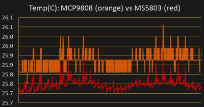
Orange is 12 bits, red is 24

The first step is a thermistor, a conceptually simple device: resistance varies with temperature (seriously, how much more simple can a sensor get?). You can measure them by tapping the center of a voltage divider the same way you’d measure any other resistance, but [Edward] had discarded this idea because the naive approach combined with his Arduino’s 10 bit ADC yielded resolution too poor to be worthwhile for his needs. But by using the right analog reference voltage and adjusting the voltage divider he could get a 20x improvement in resolution, down to 0.05°C in the relevant temperature range. This and more is the subject of the first post.

What comes next? Oversampling. Apparently fueled by a project featured on Hackaday back in 2015 [Edward] embarked on a journey to applying it to his thermistor problem. To quote [Edward] directly, to get “n extra bits of resolution, you need to read the ADC four to the power of n times”. Three bits gives about an order of magnitude better resolution. This effectively lets you resolve signals smaller than a single sample but only if there is some jitter in the signal you’re measuring. Reading the same analog line with no perturbation gives no benefit. The rest of the post deals with the process of artificially perturbing the signal, which turns out to be significantly complex, but the result is roughly 16 bit accuracy from a 10 bit ADC!

What’s the upside? High quality sensor readings from a few passives and a cheap Arduino. If that’s your jam check out this excellent series when designing your next sensing project!