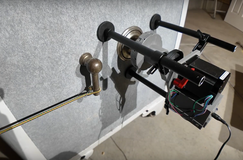
When attempting to secure something, whether it’s a computer, sensitive data, or valuables, there’s always going to be a way to break that security. It might be impossibly hard, like taking centuries to brute-force an encryption algorithm, but it’s weakness is still there. And, like the future might make certain encryption obsolete, modern electronics has made security of the past somewhat obsolete as well. [Startup Chuck] has been using tools the creators of safes from the late 1800s could probably not have imagined.
The tool that [Startup Chuck] has come up with is known as an autodialer in the safe-cracking world, and as its name suggests it automates the process of opening the safe by trying as many combinations as possible. The autodialer attaches to the safe with three magnetic feet and couples to the dial through a chuck attached to a magnetic clutch, which allows the autodialer to disengage as soon as the correct combination is found. It’s driven with a stepper motor which can test out combinations so fast that [Startup Chuck] needed to take 240 fps video and slow it down to make sure that the mechanism was behaving properly.
The autodialer itself can’t actually open the safe, though. The last step of the process is taken care of by a bungie cord, attached to the safe handle to pre-tension it enough so that when the correct combination is finally entered the safe pops open automatically. For anyone looking to duplicate the project, [Startup Chuck] has added the program code to a GitHub page. If you’re looking at a more modern safe, though, there are of course ways to crack their security systems as well.
Home automation is a popular project to undertake but its complexity can quickly become daunting, especially if you go further than controlling a few lights (or if you’re a renter). To test the waters you may want to start with something like this home safety monitor, which is an IoT device based on an Arduino. It allows remote monitoring of a home for things such as temperature, toxic gasses, light, and other variables, which is valuable even if you don’t need or want to control anything.
The device is built around an Arduino Nano 33 IOT which has WiFi and Bluetooth capabilities as well as some integrated security features. This build features a number of sensors including pressure/humidity, a gas/smoke detector, and a light sensor. To report all of the information it gathers around the home, an interface with Ubidots is configured to allow easy (and secure) access to the data gathered by the device.
The PCB and code for the project are all provided on the project page, and there are a number of other options available if Ubidots isn’t your preferred method of interfacing with the Internet of Things. You might even give Mozilla’s WebThings a shot if you’re so inclined.
Arduino Create Agent is a plug-in that was designed to help Arduino users connect their devices to the Arduino Create platform. The plug-in lets your browser communicate with your device’s serial port from a web application.
We chose Bitrock’s InstallBuilder, a powerful and easy to use cross-platform installer creation tool, for generating the Arduino Create Agent installers (Windows, macOS, Linux). Those binaries are then served through our global CDN.
Yesterday, Bitrock has published an important security advisory in which they stated that Windows binaries generated with InstallBuilder versions earlier than 19.7.0 are vulnerable to tampering even if they contain a valid Authenticode signature. A specially crafted payload can be appended to an existing installer and trick the installer initialization code to execute code included in it, while the existing signature remains valid.
The issue, originally reported to them by Youfu Zhang of Chaitin Security Research Lab (@ChaitinTech), got addressed by releasing an updated version of InstallBuilder so all their customers could re-build and re-release their installers. CVE-2019-5530 has been assigned to this issue (CVSSv3 score of 6.7).
Once we’ve been notified, and given the potential impact of this security issue, we worked around the clock to re-build and re-release our Agent’s Windows installer. Version 1.1.89 has now been released through our official channels.
Please note that all versions of the Windows installer before version 1.1.89 are vulnerable to CVE-2019-5530.
Because this issue can be exploited with existing binaries already released, we also want to remind all of you to only download installers from official sources.
If you have any questions regarding this security issue, or if you need any help with upgrading your installer, please do not hesitate to contact Arduino Support through e-mail at support@arduino.cc.
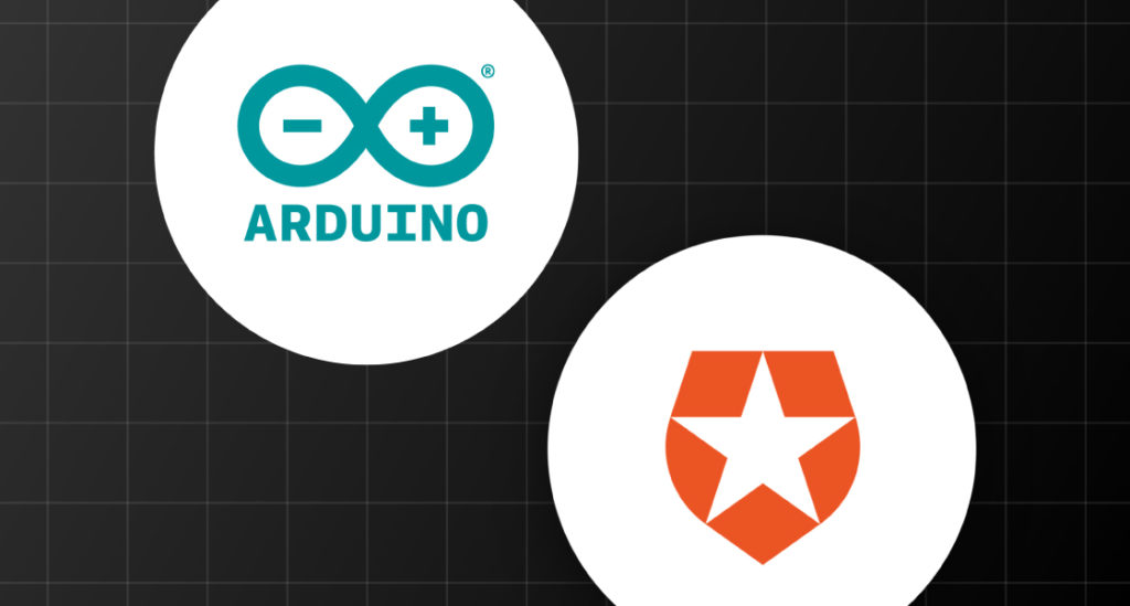
We are excited to announce that we’ve selected Auth0 as the identity management platform of choice for Arduino. We will replace our own Single Sign On solution with Auth0 for all public facing web properties, including Arduino Create and other apps.
We discovered that our own homegrown authentication solution would not scale to meet the rapidly developing needs of the growing global community and decided to reach out to Auth0. In addition to Single Sign On, Arduino will take advantage of Auth0’s new Universal Login, which enables developers to completely customise their branded authentication experiences quickly, and Device Flow for browserless or input-constrained devices.
“We wanted a robust platform to replace our SSO solution but also give us the flexibility to do cool, new things in the device authentication space. Auth0 is a brand we admire, and their API-based approach makes it easy to migrate our login data in a way that’s completely transparent for the customer. We are excited to welcome them to our global community.” – Gianluca Varisco, Arduino CISO
We plan to leverage the power of both communities and events, and explore a technical partnership in the IoT domain. Auth0 currently secures more than 2.5 billion logins per month for 21 million users.
“I have been using Arduino for years as the brain for my personal projects, so working with them in a business capacity is really rewarding. When you empower the developer with simple, powerful tools, the whole business benefits. We are excited by the reach of the Arduino community and aligned in our mission to help the developer in their journey to innovate.” – Eugenio Pace, Auth0 CEO and co-founder
Spending an hour or two around any consumer-level padlock or house deadbolt lock with a simple lockpicking kit will typically instil a good amount of panic and concern about security. While it’s true that any lock can be defeated, it’s almost comically easy to pick basic locks like this. So, if you’re looking for a level of security that can’t be defeated in two minutes with a tiny piece of metal, you might want to try something a little more advanced.
This project stemmed from an idea to use a YubiKey, a USB hardware token typically used for two-factor authentication, for physical locks instead. The prototype was built around an Arduino UNO, and all of the code and build instructions are available on the project’s site. The creator, [rprinz08], does not have one built inside of a secure enclosure so that would remain an exercise for the reader, but the proof-of-concept is interesting and certainly useful.
While digital keys like this can have their own set of problems (as all locks do), this would be a great solution for anyone needing to lock up anything where physical keys are a liability or a nuisance, where logging is important, or where many people need access to the same lock. The open source code and well-known platform make it easy for anyone to build, too.
A little less than a month ago, I joined Arduino as their Chief Information Security Officer. I’ve been in touch with the team for the past couple of months and feel incredibly lucky to be part of such a talented and driven group of people.
We’re working hard on developing a robust, well-rounded security program that fits our organisation and busy improving our security posture across all departments. I am a true believer that it all starts from introducing a strong culture of security awareness — where employees feel confident and empowered to take action against security issues.
Today, I’m thrilled to announce the first release of Arduino’s Coordinated Vulnerability Disclosure (CVD) Policy.
We used some great references when putting it together and we’d like to give them a shout out here: HackerOne’s VDP guidelines, CEPS’ report on “Software Vulnerability Disclosure in Europe,” and the US DoJ Cyber Security unit’s VDP framework. We also took into consideration recent Senate testimony of experts in vulnerability disclosure in the role hackers can play in strengthening security, Dropbox’s announcement on protecting researchers and 18F’s own policy. I even wanted to publicly thank Amit Elazari Bar On, a doctoral law candidate (J.S.D.) at UC Berkeley School of Law and a Lecturer at UC Berkeley School of Information Master in Cybersecurity program for her useful advices and for providing the amazing “#legalbugbounty” standardisation project.
We’re also happy to announce that all of the text in our policy is a freely copyable template. We’ve done this because we’d like to see others take a similar approach. We’ve put some effort in to this across our teams and if you like what you see, please use it. Similarly, if you have improvements to suggest, we’d love to hear from you.
What is CVD?
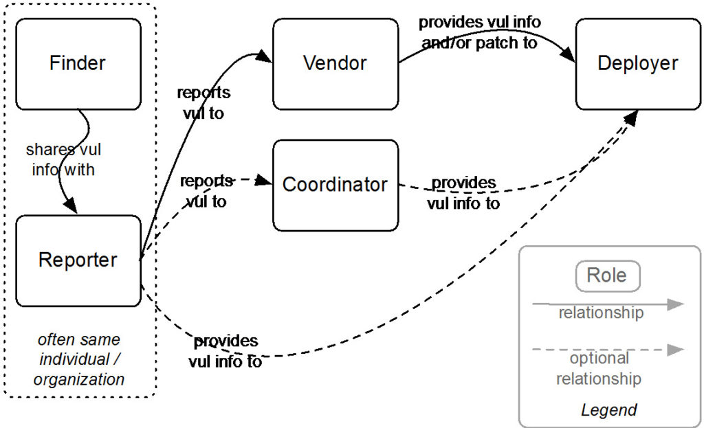
Coordinated vulnerability disclosure (CVD) is a process aimed at mitigating/eradicating the potential negative impacts of vulnerabilities. It can be defined as “the process of gathering information from vulnerability finders, coordinating the sharing of that information between relevant stakeholders, and disclosing the existence of vulnerabilities and their mitigation to various stakeholders, including the public.”
Figure 1: Relationships among actors in the CVD process. Source: “The CERT Guide to Coordinated Vulnerability Disclosure,” Software Engineering Institute, Carnegie Mellon University
Why is it important for us?
At Arduino, we consider the security of our systems and products a top priority. No technology is perfect, and Arduino believes that working with skilled security researchers across the globe is crucial in identifying weaknesses in any technology. We want security researchers to feel comfortable reporting vulnerabilities they’ve discovered, as set out in this policy, so that we can fix them and keep our information safe.
If you believe you’ve found a security issue in our products or services, we encourage you to notify us. We welcome working with you to resolve the issue promptly.
This policy describes how to send us vulnerability reports and how long we ask security researchers to wait before publicly disclosing vulnerabilities.
Of all the ways to open up a lock, there are some tried and true methods. Keys, combinations, RFIDs, picks, and explosives have all had their time and place, but now someone else wants to try something new. [Erik] has come up with a lock that opens when it is shown a pattern of colors.
The lock in question uses a set of color coded cards as the “keys”. When the cards are inserted in the lock, a TCS230 color sensor interprets the pattern on the cards and sends the information over to an Arduino Uno. From there, the Arduino can command the physical lock to open if the pattern is a match, although [Erik] is still waiting on the locking mechanism to arrive while he continues to prototype the device.
This is a fairly unique idea with a number of upsides. First, the code can’t be “stolen” from inside a wallet like RFID cards can. (Although if you can take a picture of the card all bets are off.) If you lose your key, you can simply print another one, and the device is able to handle multiple different keys and log the usage of each one. Additionally, no specialized equipment is needed to create the cards, unlike technologies that rely on magnetic strips. Of course, there’s always this classic way of opening doors if you’d rather go old school with your home locks.
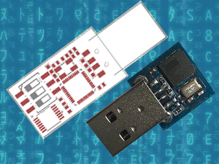
A while back, I wrote an article about Malduino, an Arduino-based, open-source BadUSB device. I found the project interesting so I signed up for an Elite version and sure enough, the friendly postman dropped it off in my mail box last Friday, which means I got to play around with it over the weekend. For those who missed the article, Malduino is USB device which is able to emulate a keyboard and inject keystrokes, among other things. When in a proper casing, it will just look like a USB flash drive. It’s like those things you see in the movies where a guy plugs in a device and it auto hacks the computer. It ships in two versions, Lite and Elite, both based on the ATmega32U4.
The Lite version is really small, besides the USB connector it only contains a switch, which allows the user to choose between running and programming mode, and a LED, which indicates when the script has finished running.
Original Malduino Elite sketch and Lite prototype
The Elite version is bigger, comes with a Micro-SD card reader and four DIP switches, which allow the user to choose which script to run from the card. It also has the LED, which indicates when a script has finished to run. This allows the user to burn the firmware only once and then program the keystroke injection scripts that stored in the Micro-SD card, in contrast to the Lite version which needs to be flashed each time a user wants to run a different script.
These are the two Malduinos and because they are programmed straight from the Arduino IDE, every feature I just mentioned can be re-programmed, re-purposed or dropped all together. You can buy one and just choose to use it like a ‘normal’ Arduino, although there are not a lot of pins to play around with. This freedom was one the first things I liked about it and actually drove me to participate in the crowd-funding campaign. Read on for the full review.
The Hardware
Malduino Elite vs USB flash drive
So the Elite board arrived as schedule and I found myself some time to look an it. Despite being longer than the Lite version, it’s still quite small, measuring roughly 4.6 cm x 1.1 cm (around 1.8 in x 0.43 in), which you can easily adapt to an old USB case, although you’ll have to cut some holes for the DIP switches and the Micro-SD card. In the crowd-funding campaign, the original sketch was for a 3 DIP switch version but the final Elite has four, which I found nice. I plugged it in to an old computer, after some consideration about which firmware it could ship with and what it could do to my laptop, and sure enough a red LED appeared. And that was it. Nothing else.
After playing around with the switches and exercising some RTFM, I realised that the firmware it ships with is probably some sort of Q.C. test for the dips, which makes the Malduino output the numbers 1 to 4 (actually simulating a keypress 1 to 4), depending on which switches are ON. So far so good, it works and I’ve seen worse PCB boards than this one. The board has holes for six pins, which I did not trace to the micro-controller and I don’t know what they are for.
The Setup
Setting up the Malduino requires that you have the Arduino IDE installed and up to date. You’ll need to open up the board manager and install the Sparkfun boards since the Elite is programmed as a ‘Sparkfun Pro Micro’ running at 3.3 V and 8 MHz. Then you need to go the Malduino Script Converter website which serves several purposes:
It allows to convert scripts between the Lite and Elite versions
It allows you to choose your keyboard layout language
It auto generates the Arduino project for you to import to the IDE
For the Elite version, just create a simple or even empty script to download the project, since when in ‘normal’ operation you will just flash the Malduino once and then use the Micro-SD card to store new scripts.
A note on flashing, if you are using a Debian-based distribution you might come across some problems like I did and not be able to flash the device. Like the user on this most useful post, my modem-manager was trying to talk with the Malduino after every reset and confused AVRDUDE to death. The solution is to add udev rules to “/etc/udev/rules.d/77-mm-usb-device-blacklist-local.rules”, kudos to [socrim]:
Since I’m running Linux, a quick shortcut to run a command is the ALT-F2 combination. So I script that into a file and save it to 1111.txt. The Elite searches the Micro-SD card for a file corresponding to the current dip switch state. Lets say the dip switch 2 and 4 are ON. In this case, the software tries to find the file named 0101.txt and parse its contents (as in dip switch order 1,2,3,4 and not the binary representation of the number 2 and 4) . When it finishes, the red LED starts flashing quickly. My simple script was:
DELAY 2000
ALT F2
DELAY 1000
STRING xterm
DELAY 1000
ENTER
DELAY 1000
STRING id
DELAY 1000
ENTER
But it was not working. Almost all commands worked but the ALT-F2 combo was not functioning properly. Close, but no cigar. No ALT-F2, no run command window. I’ve already lazy-browsed the source code a bit because I really didn’t have a lot of time on my hands but I needed to figure this out. The offending code was this:
A custom equals function was receiving size 3 for the strings of the Function keys, like “F2”. It was ok for “F10”, “F11” and “F12”, but failed for the rest of the keys. Changing 3 to 2 did the trick, but my Portuguese keyboard layout started to interfere with other test scripts. So I changed the code to include PT and UK layouts, changing them in a #define at compile time.
It would be cool if it was possible to access the SD card from the computer as a regular USB volume. I don’t know exactly how feasible that is, but it does not come with the current firmware. I still wanted to be able to output the content of an arbitrary file on the SD card to the screen, so I added another script function called ECHOFILEHEX that outputs the content of a file in the SD card as escape characters. For example, if the file a.txt contains “AAA”, the script command ECHOFILEHEX a.txt would output “\x41\x41\x41”. This can be useful to echo binary files into printf or echo -e, in Linux hosts at least.
Meanwhile, I had some trouble reading the original code. You know, we all have different programming styles. Don’t get me wrong, I’ve been known to write some messed-up spaghetti code. I sometimes browse old projects looking for some libs or classes I coded and wonder ‘who the heck wrote this steaming pile of code?’ Me, it was me. Anyway, I started to change a bit here and there and ended up changing pretty much the entire code. That’s the beauty and the curse of open-source. If you’re curious you can check it out here.
Conclusion
All in all, and despite some bumps, I’m quite pleased with Malduino. It is what I expected: an open platform for BadUSB attacks that’s in its infancy. It’s awesome that we can all tinker with it, modify it, make it better or just make it suit our needs. I hope a real community can start so we can see its full potential emerge. My short list includes simulating other USB devices, better SD card management, and expanding the device via the unused pins. What would you add?
It’s a long way to go and a lot can go wrong, so good luck with the project [Seytonic]!
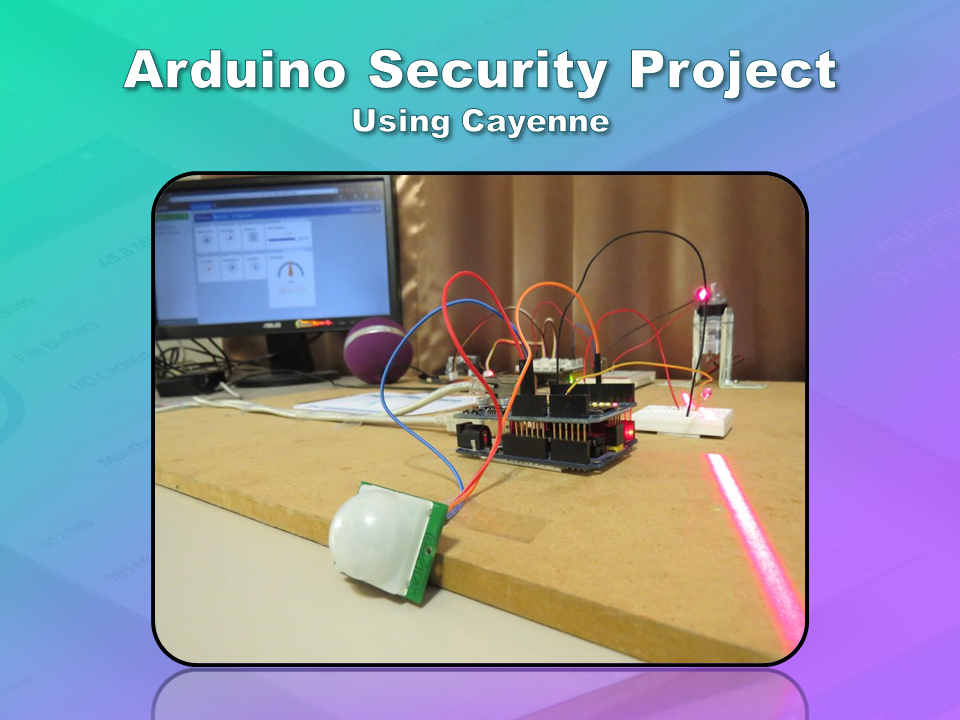
This is an Arduino based home security project that uses the power of "Cayenne" for extraordinary capabilities.
Cayenne Beta
Cayenne is a new IoT drag and drop platform originally released for the Raspberry Pi, but now available for Arduino. Cayenne makes the task of connecting your Arduino to the internet as simple as possible. All of the complexity of internet connectivity is hidden within the Cayenne library.
You can easily create a Network of Arduinos and build an IoT system which can be managed and operated within the Cayenne dashboard. This dashboard is accessible through your browser or via the Cayenne smart phone app (on IOS or Android).
The feature I liked the most, was the ability to change the position of sensors or actuators on the Arduino without having to re-upload Arduino code. I could manage the changed position from within the Cayenne platform. The other feature that I liked was the ability to setup actions based on custom triggers. You can use Cayenne to trigger a whole range of functions, for example: play a sound, move a motor, light up an LED, or to send alert notifications via email or SMS.
Cayenne is in Beta at the moment, so there are a few minor bugs here and there, but overall - I give it a thumbs up - it is definitely worth checking out.
In order to fully experience this new IoT platform, I decided to create a project to really put it through its paces. This is what my Security Project will need:
It will use two Arduinos, one connected to the internet via an Ethernet shield, and the other via WIFI.
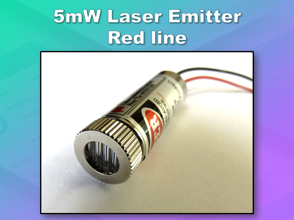
Two detectors - a PIR sensor and a laser trip wire.
If the sensors are tripped, the person has 10 seconds to present an RFID tag to the Grove RFID reader:
If a valid RFID tag is SUCCESSFULLY presented within the time limit, a nice personalised greeting will be played to that person using a Grove - Serial MP3 player
If a valid RFID FAILS to be presented within the time limit, an Alarm will sound, and I will be notified of the intrusion via an SMS alert.
The Cayenne dashboard will show the status of the sensors, and I will have full control over my security system via the web interface (or smartphone app).
The sensors will be attached to a different Arduino to that of the Grove MP3 player and the RFID tag reader, which means that there will have to be some level of communication between the two Arduinos. In fact, the cross communication will be vital to the success of this project.
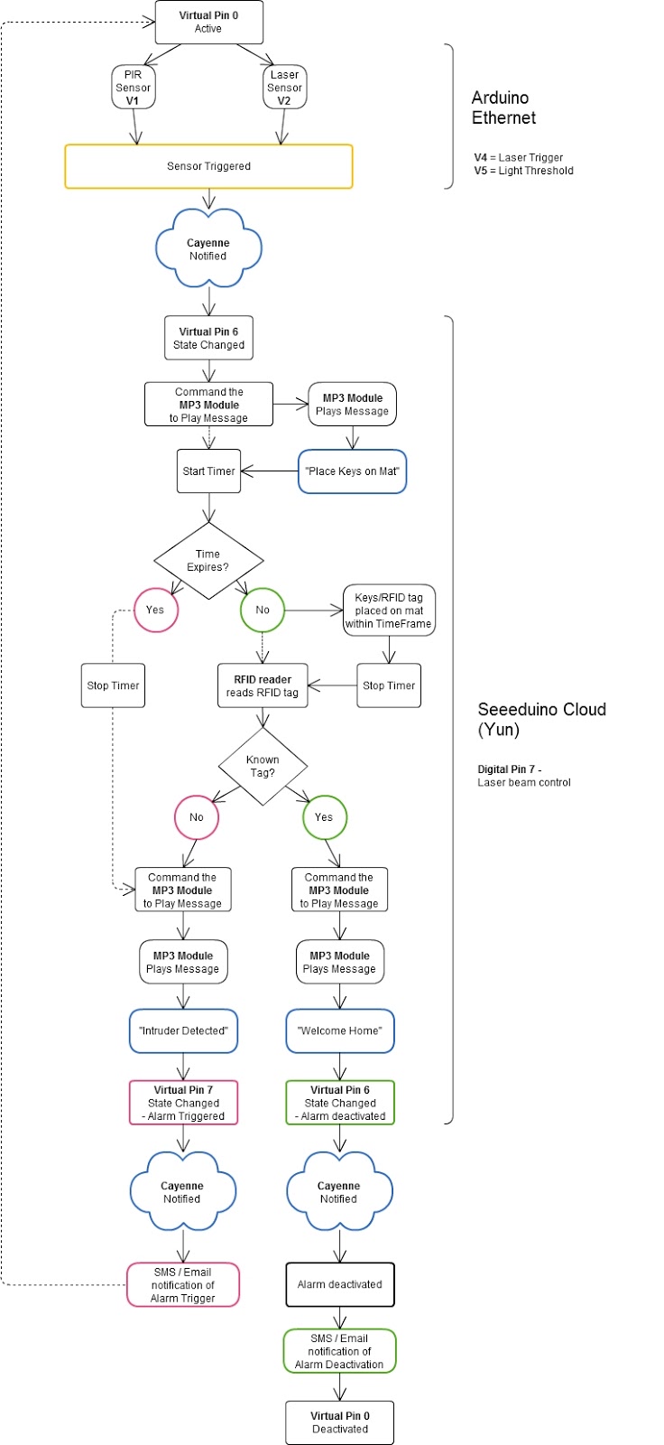
The following flow diagram shows the Security project process. It is a high level view of the decisions being made by each Arduino in response to various events.
Triggers Flow Diagram
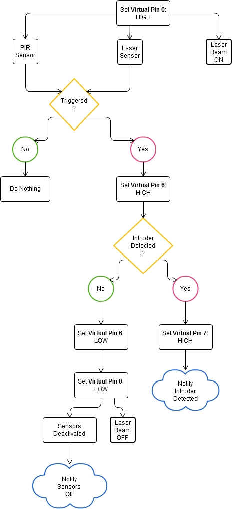
The following flow diagram aims to highlight the various triggers set up within Cayenne to get this Security system to work.
Arduino IDE and Library Downloads
You will need an Arduino IDE to upload code to the Arduino and the Seeeduino Cloud. Here is the link to the Arduino IDE: Arduino IDE - download location
The Cayenne service requires that you download and install the Cayenne Library into your Arduino IDE. You can get the Cayenne Library from here: Cayenne Library File - Download
Cayenne Connectivity Setup
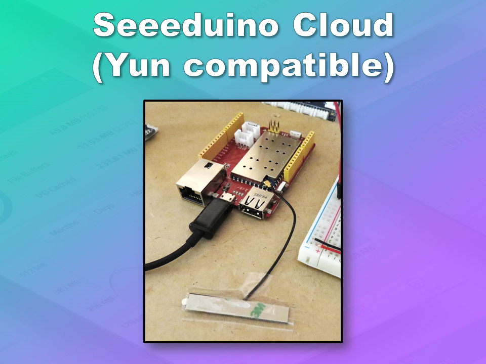
The Seeeduino Cloud needs to be prepared for use with Cayenne. Normal operating/setup instructions can be found here: Seeeduino Cloud WIKI page
Once you have successfully connected Seeeduino Cloud to your WIFI network, you can add it to the Cayenne Dashboard by making the following selections from within the Cayenne Web application:
Add New
Device/Widget
Microcontrollers
Arduino
Ensure Seeeduino Cloud is connected to WIFI network - the select the NEXT button
Select - Arduino Yun: Built-in Ethernet - ticked
Providing you have already installed the Cayenne library as described above - you should be able to copy and paste the code to the Arduino IDE and upload to the Seeeduino Cloud.
If successful, you should see the Arduino Yun board appear within the Cayenne Dashboard. If not, then seek help within the Cayenne forum.
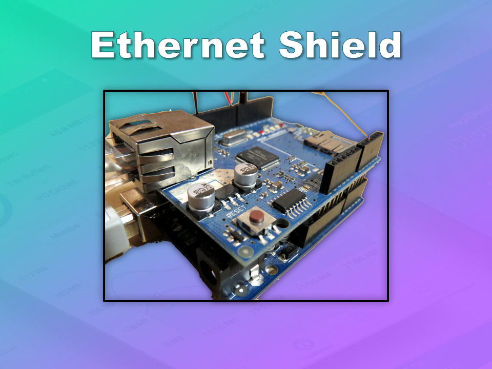
The Arduino UNO with WIZNET 5100 - Ethernet Shield also needs to be prepared with Cayenne
Add New
Device/Widget
Microcontrollers
Arduino
Ensure Arduino is powered, and Ethernet shield is connected to your internet router via an Ethernet cable
Copy and paste the code to the Arduino IDE and upload to the Arduino UNO.
If successful, you should see the Arduino Uno board appear within the Cayenne Dashboard. If not, then seek help within the Cayenne forum.
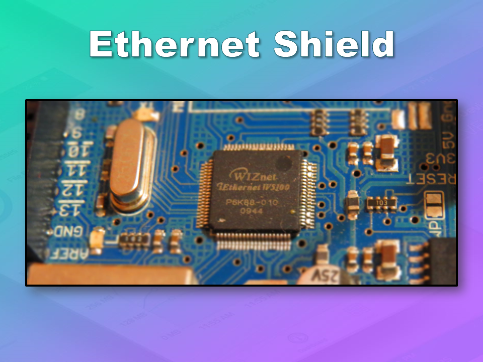
If you have the Ethernet shield with the WIZNET 5200 chip, then you may need to download a specific Ethernet library in addition to the Cayenne library.
Just follow the instructions within the Automatically generated sketch provided - when you select your specific Arduino/Ethernet/WIFI shield combination. If you need further instructions on connecting your device to Cayenne - then please visit the myDevices website for the online documentation.
ARDUINO CODE (1)
Code for Arduino UNO with Ethernet Shield:
The following code will need to be uploaded to the Arduino UNO:
ARDUINO CODE (2)
Code for Seeeduino Cloud:
The following code will need to be uploaded to the Seeeduino Cloud:
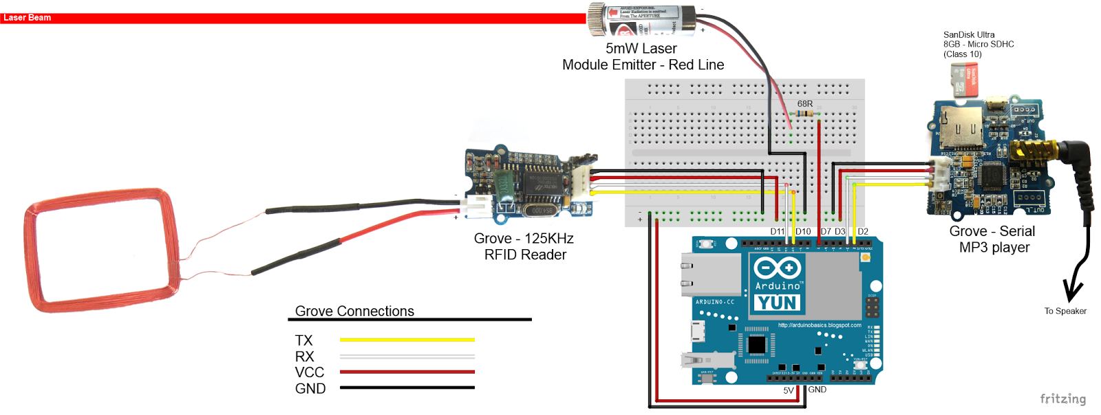
Fritzing diagram (1)
Fritzing diagram for Arduino UNO with Ethernet
Please click on the picture below for an enlarged version of this fritzing diagram
Fritzing diagram (2)
Fritzing diagram for Seeeduino Cloud
Please click on the picture below for an enlarged version of this fritzing diagram
Cayenne Dashboard Setup - GUI
The Arduino code only provides half of the functionality of this project. The Cayenne Dashboard needs to be setup to provide the rest of the functionality. The following instructions will show you how to add each of the widgets required for this Home Security project.
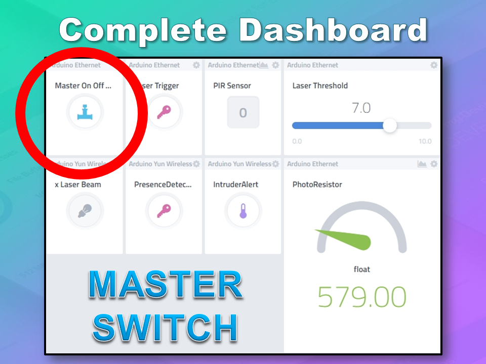
Arduino Ethernet - Master Switch
The master switch allows me to turn the security system on and off. When I turn the MASTER SWITCH ON, the laser beam will turn on, and the sensors will start monitoring the area for intruders. This widget is NOT associated with a physical switch/sensor on the Arduino - it uses virtual channel 0. We need to add the Master switch to the dashboard:
Add New
Device/Widget
Actuators
Generic
Digital Output - Control a Digital Output
Widget Name: Master On Off Switch
Select Device: Arduino Ethernet
Connectivity: Virtual
Pin: V0
Choose Widget: Button
Choose Icon: Valve
Step2: Add Actuator
We will add a trigger later to get this button to automatically turn the Laser beam on.
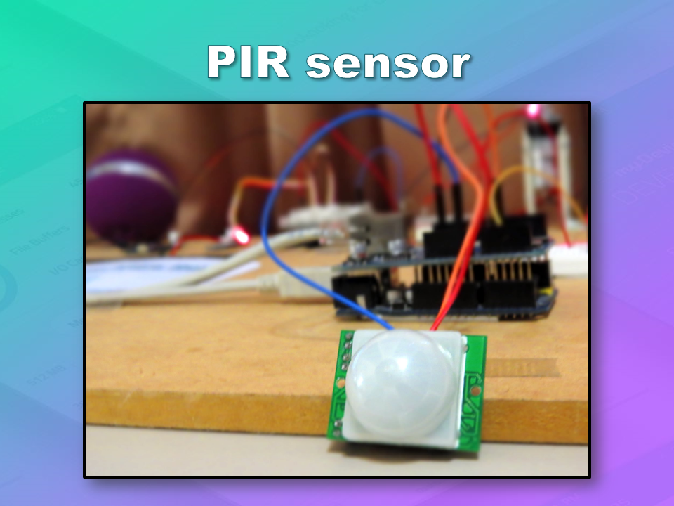
Arduino Ethernet - PIR Sensor
This sensor will be used to detect movement in the room. If a person walks into the room, this sensor will detect movement, and will trigger a message to be played on the Grove Serial MP3 player. The message will aim to get the person to identify themselves. They identify themselves by placing their RFID tag in close proximity to the Grove RFID reader. If the tag is valid, a "Welcome home" message is played on the Grove MP3 player. If a valid tag is not presented to the reader within 10 seconds, an Alarm will go off ("Alarm sound" played on Grove MP3 player.)
The PIR sensor is connected to digital Pin 6 of the Arduino, however, it is mapped to virtual pin 1 for better synchronisation with the Cayenne dashboard. This was done to capture ALL detections - as the PIR sensor could change from a LOW to HIGH and back to LOW state in between a Cayenne state check - and therefore, Cayenne could miss this motion detection.. Therefore we need to assign the PIR sensor to a virtual channel in the following way:
Add New
Device/Widget
Sensors
Motion
Digital Motion Sensor - Motion Detector
Widget Name: PIR sensor
Select Device: Arduino Ethernet
Connectivity: Virtual
Pin: V1
Choose Widget: 2-State Display
Choose Icon: Light
Step2: Add Sensor
Select Settings from the PhotoResistor
Choose Display: Value
Save
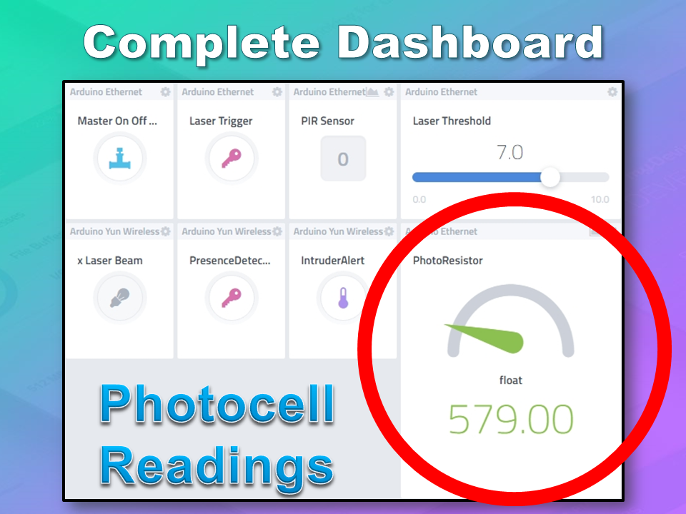
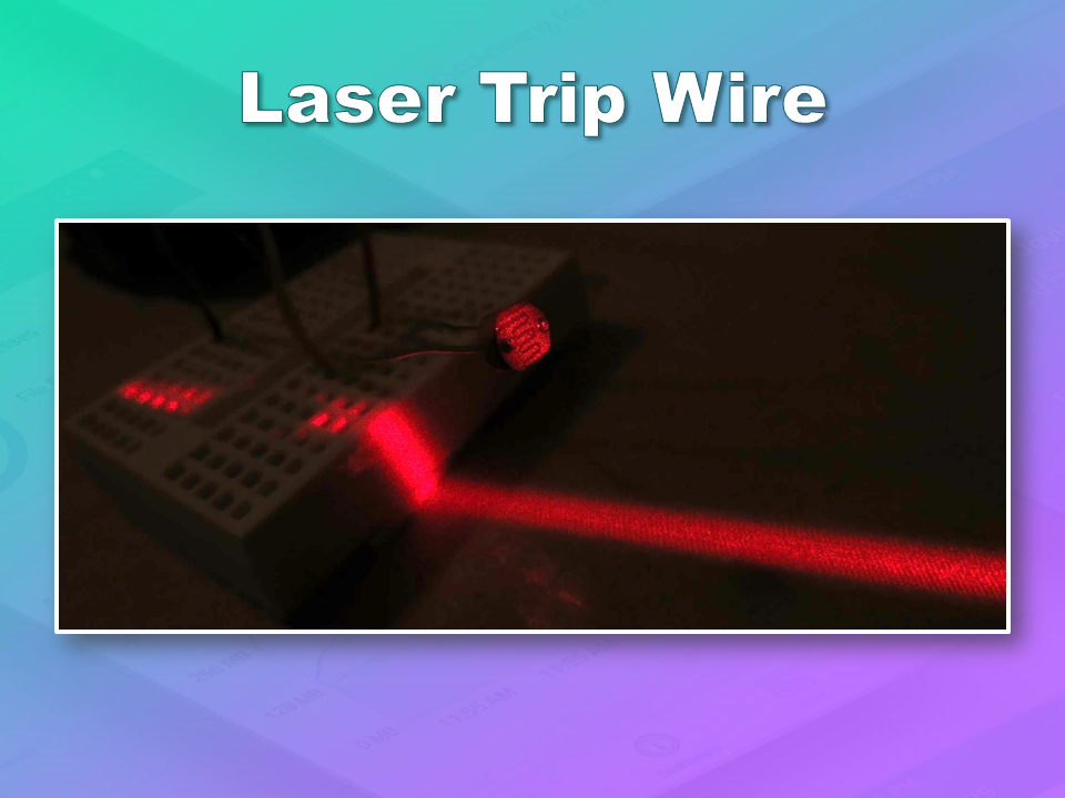
Arduino Ethernet - Photoresistor
This sensor will be used with the laser beam to create a laser tripwire. If the sensor detects a change in light levels (drops below the threshold), it will activate the laser trigger button on the dashboard. The person will then be required to identify themselves etc etc (similar to the motion detection by the PIR sensor). The photoresistor widget will display the raw analog reading from the sensor (connected to A2), but is associated with virtual channel 2. I used a virtual channel for more control over this sensor. To add the Photoresistor to the dashboard:
Add New
Device/Widget
Sensors
Luminosity
Photoresistor - Luminosity sensor
Widget Name: PhotoResistor
Select Device: Arduino Ethernet
Connectivity: Virtual
Pin: V2
Choose Widget: Value
Choose Icon: Light
Step2: Add Sensor
Arduino Ethernet - Laser Trigger
The laser trigger is just an indicator that someone tripped the laser beam. The state of this widget is used to notify the Seeeduino that a presence has been detected. This widget is associated with virtual pin 4 on the Arduino UNO with Ethernet.
Add New
Device/Widget
Actuators
Generic
Digital Output - Control a Digital Output
Widget Name: Laser Trigger
Select Device: Arduino Ethernet
Connectivity: Virtual
Pin: V4
Choose Widget: Button
Choose Icon: Lock
Step2: Add Actuator
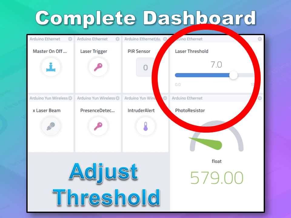
Arduino Ethernet - Laser Threshold
The laser threshold is used to manually configure the light level at which the laser trigger will trip. When the photoresistor value drops below the threshold value, the laser trigger icon will activate. This allows the threshold value to be updated from the Cayenne dashboard, rather than having to manually adjust the value in the Arduino code. Also, this threshold can be set remotely, in that you don't have to be near the Arduino to change this value. A very useful feature of this Security system. This widget is associated with virtual pin 5 on the Arduino UNO with Ethernet.
Add New
Device/Widget
Actuators
Generic
PWM Output - Control a PWM Output
Widget Name: Laser Threshold
Select Device: Arduino Ethernet
Connectivity: Virtual
Pin: V5
Choose Widget: Slider
Slider Min Value: 0
Slider Max Value: 10
Step2: Add Actuator
The max value of the slider is 10 - due to a current bug in the Cayenne software. Once resolved, this value (as well as the relevant Arduino code) will need to be updated.
Seeeduino Cloud - Presence Detected
The presence detected widget is there to notify the Seeeduino Cloud that a presence has been detected on the Arduino Uno with Ethernet shield. When the PIR sensor detects movement or if the laser tripwire is tripped, Cayenne will change the state of the Presence Detected widget from LOW to HIGH. This is used within the Seeeduino Cloud to trigger the message "Place your keys on the Mat" . If a valid RFID tag is read by the Grove RFID reader, then this widget's state will change back from HIGH to LOW, and the MasterSwitch will be deactivated - turning the Security system off. This widget is associated with Virtual pin 6 on the Seeeduino Cloud.
Add New
Device/Widget
Actuators
Generic
Digital Output - Control a Digital Output
Widget Name: Presence Detected
Select Device: Seeeduino Cloud
Connectivity: Virtual
Pin: V6
Choose Widget: Button
Choose Icon: Lock
Step2: Add Actuator
Seeeduino Cloud - Intruder Alert
If a valid RFID tag is not read by the Grove RFID reader within 10 seconds of a presence detection event, an alarm will sound, and this widget will be activated. This will trigger a notification event - to notify me of the unauthorised intrusion - via SMS or email. I will also have a visual indicator on the Cayenne dashboard that an intrusion has taken place. This widget is associated with Virtual pin 7 on the Seeeduino Cloud.
Add New
Device/Widget
Actuators
Generic
Digital Output - Control a Digital Output
Widget Name: Laser Trigger
Select Device: Seeeduino Cloud
Connectivity: Virtual
Pin: V7
Choose Widget: Button
Choose Icon: Thermometer
Step2: Add Actuator
Seeeduino Cloud - Laser Beam
The laser beam widget was created to allow for full control over the laser beam. The laser beam can be turned on or off from the Cayenne dashboard, and a connected to digital pin 7 on the Seeeduino Cloud.
Add New
Device/Widget
Actuators
Light
Light Switch - Turn On/Off a Light
Widget Name: xLaser Beam
Select Device: Seeeduino Cloud
Connectivity: Digital
Pin: D7
Choose Widget: Button
Choose Icon: Light
Step2: Add Actuator
Cayenne Triggers
Now that all of the widgets have been added to the Dashboard, there is just one more step to complete the Security System. We need to setup the triggers. These triggers provide a level of automation that is easy to create within Cayenne, but would be very complicated otherwise. I set my triggers up as per the table below. Each row represents one of the triggers within my Cayenne dashboard. If you would like to see an example of how to add a trigger - please have a look at the video at the top of this tutorial.
Concluding comments
I used many different elements to put this home/office security project together - Multiple Arduinos were connected to the internet, both controlled by a web/smart phone app, cross-communication/synchronisation between the Arduinos, and the use of multiple sensors and modules including a laser beam !
This was way more than just a simple PIR sense and alarm project. I now have a personalised greeting and reminder system when I walk in the door. Everyone else has their own personalised greeting. I can enable my Security System remotely, from two blocks away, and if I wanted to - I could enable it from the other side of the world. I know instantly when someone has entered my house/office.... with an SMS alert straight to my phone.
This project could easily be extended:
Press a button on my phone to manually trigger/play a specific message/sound/song
Take a picture of the intruder
Introduce fire or leak detection aswell
Add other environmental sensors - Temperature / Humidity
Connect it to lamp/light - creating a security light
I am sure you can think of more things I could do with this system. In fact, why don't you mention your ideas in the comments below.
Cayenne was instrumental in getting this project to work. I don't think I would know where to start if I had to do this project without this cool IoT platform. I think I will definitely be trying out a few more projects using Cayenne, and should you want to do the same, then please make sure to join Cayenne Beta:
Here is the link you need to get to the right place: Cayenne Beta Link
If you like this page, please do me a favour and show your appreciation :
This is an Arduino based home security project that uses the power of "Cayenne" for extraordinary capabilities.
Cayenne Beta
Cayenne is a new IoT drag and drop platform originally released for the Raspberry Pi, but now available for Arduino. Cayenne makes the task of connecting your Arduino to the internet as simple as possible. All of the complexity of internet connectivity is hidden within the Cayenne library.
You can easily create a Network of Arduinos and build an IoT system which can be managed and operated within the Cayenne dashboard. This dashboard is accessible through your browser or via the Cayenne smart phone app (on IOS or Android).
The feature I liked the most, was the ability to change the position of sensors or actuators on the Arduino without having to re-upload Arduino code. I could manage the changed position from within the Cayenne platform. The other feature that I liked was the ability to setup actions based on custom triggers. You can use Cayenne to trigger a whole range of functions, for example: play a sound, move a motor, light up an LED, or to send alert notifications via email or SMS.
Cayenne is in Beta at the moment, so there are a few minor bugs here and there, but overall - I give it a thumbs up - it is definitely worth checking out.
In order to fully experience this new IoT platform, I decided to create a project to really put it through its paces. This is what my Security Project will need:
It will use two Arduinos, one connected to the internet via an Ethernet shield, and the other via WIFI.
Two detectors - a PIR sensor and a laser trip wire.
If the sensors are tripped, the person has 10 seconds to present an RFID tag to the Grove RFID reader:
If a valid RFID tag is SUCCESSFULLY presented within the time limit, a nice personalised greeting will be played to that person using a Grove - Serial MP3 player
If a valid RFID FAILS to be presented within the time limit, an Alarm will sound, and I will be notified of the intrusion via an SMS alert.
The Cayenne dashboard will show the status of the sensors, and I will have full control over my security system via the web interface (or smartphone app).
The sensors will be attached to a different Arduino to that of the Grove MP3 player and the RFID tag reader, which means that there will have to be some level of communication between the two Arduinos. In fact, the cross communication will be vital to the success of this project.
The following flow diagram shows the Security project process. It is a high level view of the decisions being made by each Arduino in response to various events.
Triggers Flow Diagram
The following flow diagram aims to highlight the various triggers set up within Cayenne to get this Security system to work.
Arduino IDE and Library Downloads
You will need an Arduino IDE to upload code to the Arduino and the Seeeduino Cloud. Here is the link to the Arduino IDE: Arduino IDE - download location
The Cayenne service requires that you download and install the Cayenne Library into your Arduino IDE. You can get the Cayenne Library from here: Cayenne Library File - Download
Cayenne Connectivity Setup
The Seeeduino Cloud needs to be prepared for use with Cayenne. Normal operating/setup instructions can be found here: Seeeduino Cloud WIKI page
Once you have successfully connected Seeeduino Cloud to your WIFI network, you can add it to the Cayenne Dashboard by making the following selections from within the Cayenne Web application:
Add New
Device/Widget
Microcontrollers
Arduino
Ensure Seeeduino Cloud is connected to WIFI network - the select the NEXT button
Select - Arduino Yun: Built-in Ethernet - ticked
Providing you have already installed the Cayenne library as described above - you should be able to copy and paste the code to the Arduino IDE and upload to the Seeeduino Cloud.
If successful, you should see the Arduino Yun board appear within the Cayenne Dashboard. If not, then seek help within the Cayenne forum.
The Arduino UNO with WIZNET 5100 - Ethernet Shield also needs to be prepared with Cayenne
Add New
Device/Widget
Microcontrollers
Arduino
Ensure Arduino is powered, and Ethernet shield is connected to your internet router via an Ethernet cable
Copy and paste the code to the Arduino IDE and upload to the Arduino UNO.
If successful, you should see the Arduino Uno board appear within the Cayenne Dashboard. If not, then seek help within the Cayenne forum.
If you have the Ethernet shield with the WIZNET 5200 chip, then you may need to download a specific Ethernet library in addition to the Cayenne library.
Just follow the instructions within the Automatically generated sketch provided - when you select your specific Arduino/Ethernet/WIFI shield combination. If you need further instructions on connecting your device to Cayenne - then please visit the myDevices website for the online documentation.
ARDUINO CODE (1)
Code for Arduino UNO with Ethernet Shield:
The following code will need to be uploaded to the Arduino UNO:
ARDUINO CODE (2)
Code for Seeeduino Cloud:
The following code will need to be uploaded to the Seeeduino Cloud:
Fritzing diagram (1)
Fritzing diagram for Arduino UNO with Ethernet
Please click on the picture below for an enlarged version of this fritzing diagram
Fritzing diagram (2)
Fritzing diagram for Seeeduino Cloud
Please click on the picture below for an enlarged version of this fritzing diagram
Cayenne Dashboard Setup - GUI
The Arduino code only provides half of the functionality of this project. The Cayenne Dashboard needs to be setup to provide the rest of the functionality. The following instructions will show you how to add each of the widgets required for this Home Security project.
Arduino Ethernet - Master Switch
The master switch allows me to turn the security system on and off. When I turn the MASTER SWITCH ON, the laser beam will turn on, and the sensors will start monitoring the area for intruders. This widget is NOT associated with a physical switch/sensor on the Arduino - it uses virtual channel 0. We need to add the Master switch to the dashboard:
Add New
Device/Widget
Actuators
Generic
Digital Output - Control a Digital Output
Widget Name: Master On Off Switch
Select Device: Arduino Ethernet
Connectivity: Virtual
Pin: V0
Choose Widget: Button
Choose Icon: Valve
Step2: Add Actuator
We will add a trigger later to get this button to automatically turn the Laser beam on.
Arduino Ethernet - PIR Sensor
This sensor will be used to detect movement in the room. If a person walks into the room, this sensor will detect movement, and will trigger a message to be played on the Grove Serial MP3 player. The message will aim to get the person to identify themselves. They identify themselves by placing their RFID tag in close proximity to the Grove RFID reader. If the tag is valid, a "Welcome home" message is played on the Grove MP3 player. If a valid tag is not presented to the reader within 10 seconds, an Alarm will go off ("Alarm sound" played on Grove MP3 player.)
The PIR sensor is connected to digital Pin 6 of the Arduino, however, it is mapped to virtual pin 1 for better synchronisation with the Cayenne dashboard. This was done to capture ALL detections - as the PIR sensor could change from a LOW to HIGH and back to LOW state in between a Cayenne state check - and therefore, Cayenne could miss this motion detection.. Therefore we need to assign the PIR sensor to a virtual channel in the following way:
Add New
Device/Widget
Sensors
Motion
Digital Motion Sensor - Motion Detector
Widget Name: PIR sensor
Select Device: Arduino Ethernet
Connectivity: Virtual
Pin: V1
Choose Widget: 2-State Display
Choose Icon: Light
Step2: Add Sensor
Select Settings from the PhotoResistor
Choose Display: Value
Save
Arduino Ethernet - Photoresistor
This sensor will be used with the laser beam to create a laser tripwire. If the sensor detects a change in light levels (drops below the threshold), it will activate the laser trigger button on the dashboard. The person will then be required to identify themselves etc etc (similar to the motion detection by the PIR sensor). The photoresistor widget will display the raw analog reading from the sensor (connected to A2), but is associated with virtual channel 2. I used a virtual channel for more control over this sensor. To add the Photoresistor to the dashboard:
Add New
Device/Widget
Sensors
Luminosity
Photoresistor - Luminosity sensor
Widget Name: PhotoResistor
Select Device: Arduino Ethernet
Connectivity: Virtual
Pin: V2
Choose Widget: Value
Choose Icon: Light
Step2: Add Sensor
Arduino Ethernet - Laser Trigger
The laser trigger is just an indicator that someone tripped the laser beam. The state of this widget is used to notify the Seeeduino that a presence has been detected. This widget is associated with virtual pin 4 on the Arduino UNO with Ethernet.
Add New
Device/Widget
Actuators
Generic
Digital Output - Control a Digital Output
Widget Name: Laser Trigger
Select Device: Arduino Ethernet
Connectivity: Virtual
Pin: V4
Choose Widget: Button
Choose Icon: Lock
Step2: Add Actuator
Arduino Ethernet - Laser Threshold
The laser threshold is used to manually configure the light level at which the laser trigger will trip. When the photoresistor value drops below the threshold value, the laser trigger icon will activate. This allows the threshold value to be updated from the Cayenne dashboard, rather than having to manually adjust the value in the Arduino code. Also, this threshold can be set remotely, in that you don't have to be near the Arduino to change this value. A very useful feature of this Security system. This widget is associated with virtual pin 5 on the Arduino UNO with Ethernet.
Add New
Device/Widget
Actuators
Generic
PWM Output - Control a PWM Output
Widget Name: Laser Threshold
Select Device: Arduino Ethernet
Connectivity: Virtual
Pin: V5
Choose Widget: Slider
Slider Min Value: 0
Slider Max Value: 10
Step2: Add Actuator
The max value of the slider is 10 - due to a current bug in the Cayenne software. Once resolved, this value (as well as the relevant Arduino code) will need to be updated.
Seeeduino Cloud - Presence Detected
The presence detected widget is there to notify the Seeeduino Cloud that a presence has been detected on the Arduino Uno with Ethernet shield. When the PIR sensor detects movement or if the laser tripwire is tripped, Cayenne will change the state of the Presence Detected widget from LOW to HIGH. This is used within the Seeeduino Cloud to trigger the message "Place your keys on the Mat" . If a valid RFID tag is read by the Grove RFID reader, then this widget's state will change back from HIGH to LOW, and the MasterSwitch will be deactivated - turning the Security system off. This widget is associated with Virtual pin 6 on the Seeeduino Cloud.
Add New
Device/Widget
Actuators
Generic
Digital Output - Control a Digital Output
Widget Name: Presence Detected
Select Device: Seeeduino Cloud
Connectivity: Virtual
Pin: V6
Choose Widget: Button
Choose Icon: Lock
Step2: Add Actuator
Seeeduino Cloud - Intruder Alert
If a valid RFID tag is not read by the Grove RFID reader within 10 seconds of a presence detection event, an alarm will sound, and this widget will be activated. This will trigger a notification event - to notify me of the unauthorised intrusion - via SMS or email. I will also have a visual indicator on the Cayenne dashboard that an intrusion has taken place. This widget is associated with Virtual pin 7 on the Seeeduino Cloud.
Add New
Device/Widget
Actuators
Generic
Digital Output - Control a Digital Output
Widget Name: Laser Trigger
Select Device: Seeeduino Cloud
Connectivity: Virtual
Pin: V7
Choose Widget: Button
Choose Icon: Thermometer
Step2: Add Actuator
Seeeduino Cloud - Laser Beam
The laser beam widget was created to allow for full control over the laser beam. The laser beam can be turned on or off from the Cayenne dashboard, and a connected to digital pin 7 on the Seeeduino Cloud.
Add New
Device/Widget
Actuators
Light
Light Switch - Turn On/Off a Light
Widget Name: xLaser Beam
Select Device: Seeeduino Cloud
Connectivity: Digital
Pin: D7
Choose Widget: Button
Choose Icon: Light
Step2: Add Actuator
Cayenne Triggers
Now that all of the widgets have been added to the Dashboard, there is just one more step to complete the Security System. We need to setup the triggers. These triggers provide a level of automation that is easy to create within Cayenne, but would be very complicated otherwise. I set my triggers up as per the table below. Each row represents one of the triggers within my Cayenne dashboard. If you would like to see an example of how to add a trigger - please have a look at the video at the top of this tutorial.
Concluding comments
I used many different elements to put this home/office security project together - Multiple Arduinos were connected to the internet, both controlled by a web/smart phone app, cross-communication/synchronisation between the Arduinos, and the use of multiple sensors and modules including a laser beam !
This was way more than just a simple PIR sense and alarm project. I now have a personalised greeting and reminder system when I walk in the door. Everyone else has their own personalised greeting. I can enable my Security System remotely, from two blocks away, and if I wanted to - I could enable it from the other side of the world. I know instantly when someone has entered my house/office.... with an SMS alert straight to my phone.
This project could easily be extended:
Press a button on my phone to manually trigger/play a specific message/sound/song
Take a picture of the intruder
Introduce fire or leak detection aswell
Add other environmental sensors - Temperature / Humidity
Connect it to lamp/light - creating a security light
I am sure you can think of more things I could do with this system. In fact, why don't you mention your ideas in the comments below.
Cayenne was instrumental in getting this project to work. I don't think I would know where to start if I had to do this project without this cool IoT platform. I think I will definitely be trying out a few more projects using Cayenne, and should you want to do the same, then please make sure to join Cayenne Beta:
Here is the link you need to get to the right place: Cayenne Beta Link
If you like this page, please do me a favour and show your appreciation :