Posts with «ws2812» label

Electronic Connect 4 Console Doesn’t Use LCD

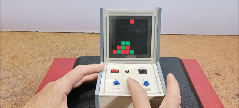
You might think that making your own electronic games would require some kind of LCD, but lately, [Mirko Pavleski] has been making his using inexpensive 8X8 WS2812B LED panels. This lets even a modest microcontroller easily control a 64-pixel “screen.” In this case, [Mirko] uses an Arduino Nano, 3 switches, and a buzzer along with some 3D printed components to make a good-looking game. You can see it in action in the video below.

The WS2812B panels are easy to use since the devices have a simple protocol where you only talk to the first LED. You send pulses to determine each LED’s color. The first LED changes color and then starts repeating what you send to the next LED, which, of course, does the same thing. When you pause a bit, the array decides you are done, and the next train of pulses will start back at the first LED.

It looks like the project is based on a German project from [Bernd Albrecht], but our German isn’t up to snuff, and machine translation always leaves something to be desired. Another developer added a play against the computer mode. This is a simple program and would be easy to port to the microcontroller of your choice. [Mirko]’s execution of it looks like it could be a commercial product. If you made one as a gift, we bet no one would guess you built it yourself.

Of course, you could play a real robot. You could probably repurpose this hardware for many different games, too.

Hack a Day 29 May 03:00

Quick and Dirty Microscope Motion Control for Focus Stacking

If you’ve spent much time looking through a microscope, you know that their narrow depth of field can be a bit challenging to deal with. Most microscopes are designed to only have a very thin slice of the specimen in focus, so looking at anything above or below that plane requires a focus adjustment. It’s tedious and fussy, and that makes it a perfect target for automation.

The goal behind [ItMightBeWorse]’s microscope mods is “focus stacking,” a technique where multiple images of the same sample taken at different focal planes can be stitched together so that everything appears to be in focus. Rather than twist knobs and take pictures manually, he built a simpler Arduino-based rig to do the job for him. Focus control is through a small stepper motor connected to the fine focus knob of the scope, while the DSLR camera shutter is triggered through a simple relay board. There’s also lighting control, with an RGB LED ring light that can change both the light level on the sample as well as the tint.

The code is very simple, and the setup is quite temporary looking, but the results are pretty impressive. We could do without the extreme closeup of that tick — nasty little arachnids — but the ant at the end of the video below has some interesting details. [ItMightBeWorse] doesn’t mention how the actual stacking is being done, but this CNC-based focus stacking project mentions a few utilities that take help with the post-processing.

The Great Resistor Embiggens the Smallest Value

With surface-mount components quickly becoming the norm, even for homebrew hardware, the resistor color-code can sometimes feel a bit old-hat. However, anybody who has ever tried to identify a random through-hole resistor from a pile of assorted values will know that it’s still a handy skill to have up your sleeve. With this in mind, [j] decided to super-size the color-code with “The Great Resistor”.

How the resistor color-code bands work

At the heart of the project is an Arduino Nano clone and a potential divider that measures the resistance of the test resistor against a known fixed value. Using the 16-bit ADC, the range of measurable values is theoretically 0 Ω to 15 MΩ, but there are some remaining issues with electrical noise that currently limit the practical range to between 100 Ω and 2 MΩ.

[j] is measuring the supply voltage to help counteract the noise, but intends to move to an oversampling/averaging method to improve the results in the next iteration.

The measured value is shown on the OLED display at the front, and in resistor color-code on an enormous symbolic resistor lit by WS2812 RGB LEDs behind.

Inside The Great Resistor, the LEDs and baffle plates make the magic work

Precision aside, the project looks very impressive and we like the way the giant resistor has been constructed. It would look great at a science show or a demonstration. We’re sure that the noise issues can be ironed out, and we’d encourage any readers with experience in this area to offer [j] some tips in the comments below. There’s a video after the break of The Great Resistor being put through its paces!

If you want to know more about the history of the resistor color code bands, then we have you covered.  Alternatively, how about reading the color code directly with computer vision?

DIY Arduino Hearing Test Device

Hearing loss is a common problem for many – especially those who may have attended too many loud concerts in their youth. [mircemk] had recently been for a hearing test, and noticed that the procedure was actually quite straightforward. Armed with this knowledge, he decided to build his own test system and document it for others to use.

Resultant audiogram from the device showing each ear in a different color

By using an Arduino to produce tones of various stepped frequencies, and gradually increasing the volume until the test subject can detect the tone, it is possible to plot an audiogram of hearing threshold sensitivity.  Testing each ear individually allows a comparison between one side and the other.

[mircemk] has built a nice miniature cabinet that holds an 8×8 matrix of WS2812 addressable RGB LEDs.  A 128×64 pixel OLED display provides user instructions, and a rotary encoder with push-button serves as the user input.

Of course, this is not a calibrated professional piece of test equipment, and a lot will depend on the quality of the earpiece used.  However, as a way to check for gross hearing issues, and as an interesting experiment, it holds a lot of promise.

There is even an extension, including a Class D audio amplifier, that allows the use of bone-conduction earpieces to help narrow down the cause of hearing loss further.

There’s some more information on bone conduction here, and we’ve covered an intriguing optical stimulation cochlear implant, too.

Speed up CircuitPython LED animations 10x!

In many LED animations, you need to apply an operation to all LEDs as fast as possible. Often this is “fadeToBlackBy”, i.e. “dim all LEDs by some amount”. There are some common effects that you can easily get back using that and one other action. For example: the Cylon effect is “Turn an LED on, [...]

DIY Neopixel / WS2812 Development Kit

If you are like me, you play around with Neopixel / WS2812-style LEDs a lot. Normally I solder my own custom-connectors and don’t use the ones that come with the reels I buy. But since we’ve been playing around with WS2812-compatible Xmas lights, I decided to make a “Neopixel Dev Kit” for easier experimenting with [...]
Todbot 08 Jan 21:09

WS2812-compatible “fairy light” LEDs that know their address

I’ve not done much on our plotter Xmas tree this week because, well… if you follow me on Twitter, it’s likely you’ve seen me ramble on about these crazy new Christmas Tree lights we got for our tree (first tree ever!). They appeared to maybe be WS2812 / Neopixel compatible and yup, they were! But [...]
Todbot 01 Jan 21:49

Unique Clock Keeps Time the Fibonacci Way

You say your binary clock no longer has the obfuscation level needed to earn the proper nerd street cred? Feel like you need something a little more mathematically challenging to make sure only the cool kids can tell the time? Then this Fibonacci clock might be just the thing to build.

Granted, [TecnoProfesor]’s clock is a somewhat simplified version of an earlier version that was nigh impossible to decode. But with its color coding and [Piet Mondrian]-esque grids, it’s still satisfyingly difficult to get the time from a quick glance. The area of the blocks represents the Fibonacci sequence 1, 1, 2, 3, 5, and adding up which blocks are illuminated by the RGB LEDs behind the frosted front panel. That lets you tally up to 12 intervals; for the minutes and seconds, there are indicators for the powers of 12 up to 48. Put it all together and you’ve got a unique and attractive graphical time display that’s sure to start interesting conversations when the mathematically disinclined try to use it. Check out the video below as the clock goes from 12:28:01 to 12:28:46. We think.

If this doesn’t scratch your itch for obfuscated clocks, we’ve got plenty of them. From random four-letter words to an analog digital clock to an epic epoch clock, we’ve got them all.

The Smartest Smart Watch is the One You Make Yourself

If you’re building a smart watch these days (yawn!), you’ve got to have some special sauce to impress the jaded Hackaday community. [Dominic]’s NeoPixel SmartWatch delivers, with his own take on what’s important to have on your wrist, and just as importantly, what isn’t.

There’s no fancy screen. Instead, the watch gets by with a ring of NeoPixels for all its notification needs. But notification is what it does right. It tells [Dominic] when he’s got an incoming call of course, but also has different flashing color modes for SMS, Snapchat, and e-mail. Oh yeah, and it tells time and even has a flashlight mode. Great functionality for a minimalistic display.

But that’s not all! It’s also got a light sensor that works from the UV all the way down to IR. At the moment, it’s being used to automatically adjust the LED brightness and to display current UV levels. (We imagine turning this into a sunburn alarm mode.) Also planned is a TV-B-Gone style IR transmitter.

The hardware is the tough part of this build, and [Dominic] ended up using a custom PCB to help in cramming so many off-the-shelf modules into a tiny space. Making it look good is icing on the cake.

Thanks [Marcello] for the tip!


Filed under: clock hacks
Hack a Day 13 Mar 09:01
arduino  clock  clock hacks  ir  neopixel  uv  watch  ws2812  

Making a Mega LED Desk

Few things beat a sturdy, home-built desk — especially when it’s jam-packed with over 1200 WS2812 LEDs.

[nolobot] and his bother struggled with setting up and squaring-off the t-slotted, extruded aluminium frame which makes up the desk. He recommends practicing with a smaller frame for anyone else attempting a similar build. The surface of the desk has a few inches between the polycarbonate top and the 1/4″ plywood painted black serving as the substrate for the LEDs. Those LEDs come in strip form but still required several hundred solders, and wiring headaches in an attempt to make future upgrades manageable. Dozens of support bolts with adjustable feet support the desk surface throughout. These all had to be individually adjusted and can be made out if you look closely at the demo videos.

An Arduino Mega controls the LEDs with the help of the FastLED library. Custom code was necessary because one of the major issues [nolobot] faced was the power draw. 1200 LEDs at 5V draw quite a bit of current, so the LEDs were coded to peak at about 50% brightness. The matrix was split into different banks, while also limiting the 40A PSU to only 15A.

Regarding the final product, all we can say is: woah.

Not a fan of putting this much work into a piece of furniture? There are also ultra-minimalist options at your disposal.

[via /r/arduino]


Filed under: Android Hacks, led hacks
Hack a Day 02 Mar 12:01