Maker Display to Ubidots MQTT button

Description
This tutorial will show you how to create a simple MQTT connection to Ubidots. You will also learn to configure the necessary MQTT subscription to a button on the Ubidots dashboard, and control a Maker Display (ESP-12E compitible board) from anywhere in the world. The process may seem a bit daunting at first, but hopefully by the end of this tutorial, you will feel comfortable creating your own Ubidots MQTT subscriptions.
Parts Required
- Maker Display 2 or Node MCU (ESP-12E) module
- NOVA programmer
- USB mini-B cable
- WiFi internet connection
- Ubidots account (free)
The Maker display 2 has an inbuilt ESP8266MCD WiFi module which will be used to create the MQTT connection to the Ubidots broker (online).
Ubidots Setup
This tutorial requires a FREE Ubidots account.
Go to this site to sign up: https://ubidots.com/education/
Once signed up, you will need to configure Ubidots using the following instructions.
Create a device
Create a variable
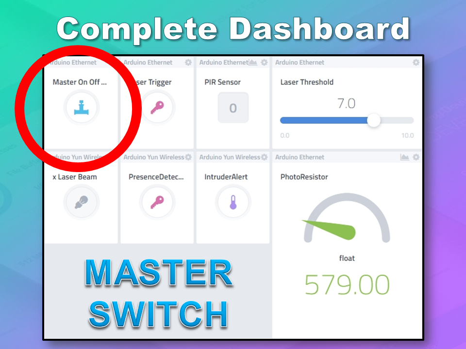
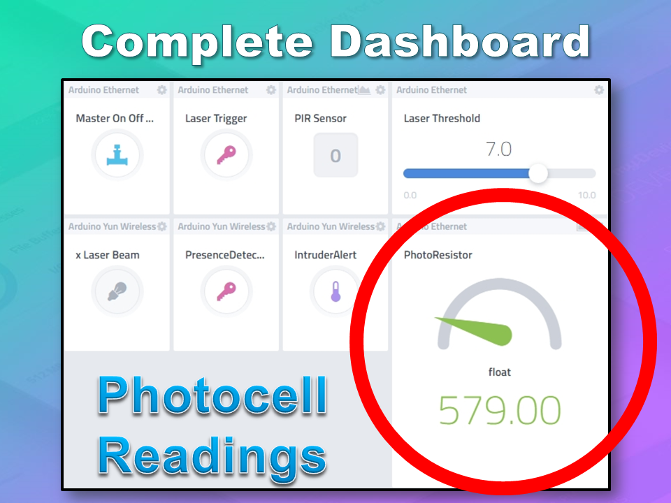
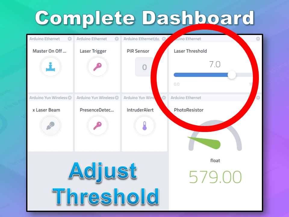
Create a dashboard
Add a Widget
Create a Ubidots TOKEN
Take note of key information
Now that the Ubidots Dashboard is set up, you will need to ensure you have 3 sets of information to insert into the code.
Ubidots slideshow of the setup process
Arduino IDE
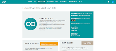
While there are many Arduino IDE alternatives out there, I would recommend that you use the official Arduino IDE for this project. I used the official Arduino IDE app (v1.8.5) for Windows 10.
Make sure to get the most up-to-date version for your operating system here.
Additional Boards Manager URLS
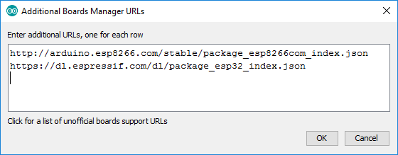
Make sure to add the following URLs to your "additional boards manager URL" setting:- File > Preferences > Additional Boards Manager URLS:
- http://arduino.esp8266.com/stable/package_esp8266com_index.json
- https://dl.espressif.com/dl/package_esp32_index.json
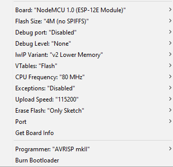
Select Tools > Board: "NodeMCU 1.0 (ESP-12E Module)" board.
Then check that you have the following settings:
Libraries required
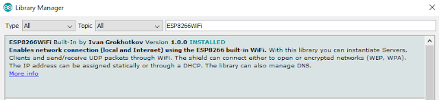
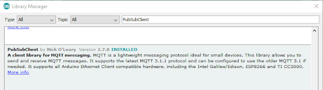
This tutorial makes use of two libraries: ESP8266WiFi.h and PubSubClient.h.
- ESP8266WiFi.h : This library is required for the WiFi connection to the internet. More info.
- PubSubClient.h : Is used to create an MQTT Client to handle the communication between the Ubidots MQTT broker and the Maker Display2 (or ESP-12E).
Both libraries can be installed via the library manager: Sketch > Include library > Manage Libraries
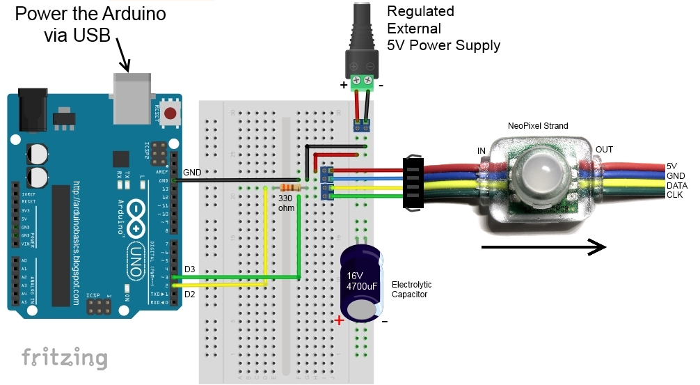
Arduino Code
Connect the NOVA programmer to the Maker Display 2
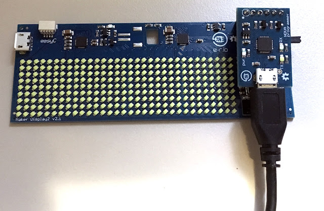
Remember that you will need to insert the 3 bits of information from the "Ubidots" section, into the code. You will also need to know your WiFI SSID name, and password. Copy the code below into the Arduino IDE, make the necessary changes in the sketch to reflect the API labels and tokens from your Ubidots account. Connect the USB cable to the computer, select the correct COM port (Tools > Port), then upload the code to the Maker display board.
The code is available on my GitHub repository. Or you can have a look at the fully commented code below.
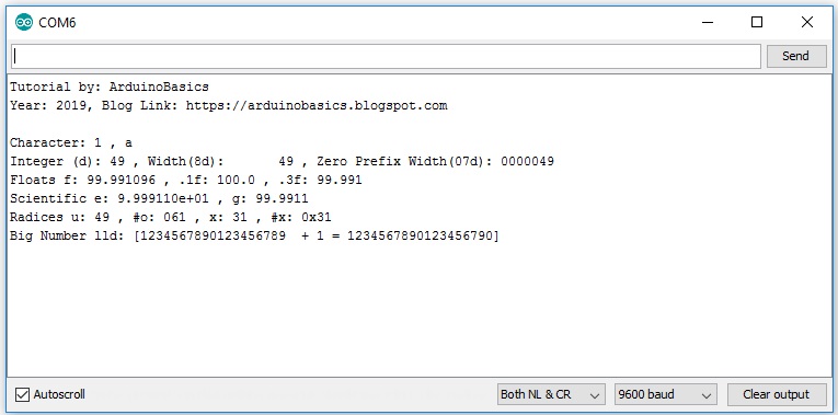
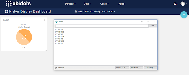
Open the Serial monitor (ctrl + shift + M), ensure the Baud is set to 9600, and then press the button on the Ubidots Maker Display Dashboard. You should see messages appear in the Serial monitor that correspond with the state of the button.
Code Explained
A number of different information sources were utilised to construct the code above. These sources were acknowledged within. As noted before, the code uses two libraries, one to simplify the WiFi connection to the internet, and the other to simplify the connection of the Maker Display to the Ubidots MQTT broker.
setup()
The setup() function is used to establish the WiFi connection, set the MQTT broker, and define the callback function - which will be called each time the button on the Ubidots dashboard is pressed.
loop()
The loop() function is responsible for connecting to the MQTT broker, and polling for messages from the MQTT broker using the client.loop() function.
callback()
The callback() function first checks the "topic" message coming from the MQTT broker, and compares it to the buttonTopic variable. The buttonTopic variable in this sketch is equal to "/v1.6/devices/maker-display/button1/lv". You will notice that the variable is constructed using the "device API label", and the "button API label". The other components of the buttonTopic are always the same. eg.
This comparison allows us to differentiate this particular button from other potential components on the Ubidots dashboard. The value of the button (on=1/off=0), is transmitted from the MQTT broker each time the button is pressed on the Ubidots Maker Display dashboard. It is captured by the "payload" variable in the callback function. If the payload variable is equal to 1 (on), then a Serial message will be transmitted "BUTTON ON". If the payload variable is equal to 0 (off), then a Serial message will be transmitted "BUTTON OFF". You will be able to see this message come through by opening the Serial Monitor (ctrl+shift+M) within the Arduino IDE.
MQTTconnect()
The MQTTconnect() function is responsible for connecting to the MQTT broker. It requires a Ubidots TOKEN, a unique MQTT client name and a pre-defined port (1883). In order to receive messages from the button on the Ubidots Maker Display dashboard, we need to subscribe to button. But first we need to construct the string location of the button variable.
We do this using the sprintf() function.
If you would like to learn more about the sprintf function have a look at my tutorial here.
The sprintf function is used to construct the string in a specific format, and in this case it uses the DEVICE_LABEL, and VARIABLE_LABEL1, and assigns the string to the buttonTopic variable. Once constructed the buttonTopic variable is used to subscribe to the button on the Ubidots dashboard.
The program is instructed to retry the connection attempt every 2 seconds if it fails to connect for any reason.
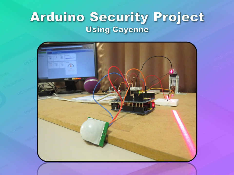
Project in Action

Conclusion
Setting up the Ubidots dashboard and the Arduino IDE takes up the majority of the time in this project. Once all the configurations are made, the rest is pretty simple. I hope by the end of this tutorial, you will have learnt how to create a button on a Ubidots dashboard, and interface it with a Maker Display (ESP-12 compatible board).
While there are plenty of examples on the Ubidots website that will show you how to push data to the dashboard, I found that the opposite was not true. There are limited examples that show you how to control your device from a Ubidots widget. I know that this example is not that exciting, but hopefully, you understand the significance of the information, and understand how easy it would be to modify the sketch above to make it more exciting. However, I did not want to over-complicate the tutorial with other complexities. Perhaps in the next tutorial we will use the information gained here, to do something a bit more thrilling. But at least now you know the basics. We can now:
- Program a Maker Display
- Add widgets to a Ubidots dashboard
- Control the Maker Display using widgets from a Ubidots dashboard (using MQTT)
If you found this tutorial helpful, please consider supporting me by buying me a virtual coffee/beer.
Social Media
You can find me on various social networks:
Follow me on Twitter: ScottC @ArduinoBasics.
I can also be found on Instagram, Pinterest, and YouTube.
And if all else fails, I have a server on Discord.