Posts with «photocell» label

Compact M&M Sorter Goes Anywhere

Let’s face it — eating different colored candy like M&Ms or Skittles is just a little more fun if you sort your pile by color first. The not-fun part is having to do it by hand. [Jackofalltrades_] decided to tackle this time-worn problem for engineering class because it’s awesome and it satisfies the project’s requirement for sensing, actuation, and autonomous sequencing. We’d venture to guess that it satisfies [Jackofalltrades_]’ need for chocolate, too.

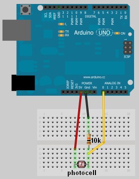
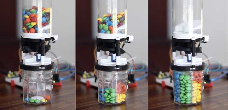
Here’s how it works: one by one, M&Ms are selected, pulled into a dark chamber for color inspection, and then dispensed into the proper cubby based on the result. [Jackofalltrades_] lived up to their handle and built a color-detecting setup out of an RGB LED and light-dependent resistor. The RGB LED shines red, then, green, then blue at full brightness, and takes a voltage reading from the photocell to figure out the candy’s color. At the beginning, the machine needs one of each color to read in and store as references. Then it can sort the whole bag, comparing each M&M to the reference values and updating them with each new M&M to create a sort of rolling average.

We love the beautiful and compact design of this machine, which was built to maximize the 3D printer as one of the few available tools. The mechanical design is particularly elegant. It cleverly uses stepper-driven rotation and only needs one part to do most of the entire process of isolating each one, passing it into the darkness chamber for color inspection, and then dispensing it into the right section of the jar below. Be sure to check out the demo after the break.

Need a next-level sorter? Here’s one that locates and separates the holy grail of candy-coated chocolate — peanut M&Ms that didn’t get a peanut.

[Emily]’s Eerie Educational Electric Eyeball Entertains

Like many of us, [Emily’s Electric Oddities] has had a lot of time for projects over the past year or so, including one that had been kicking around since late 2018. It all started at the Hackaday Superconference, when [Emily] encountered the Adafruit Hallowing board in the swag bag. Since that time, [Emily] has wanted to display the example code eyeball movement on a CRT, but didn’t really know how to go about it. Spoiler alert: it works now.

See? It’s educational.

Eventually, [Emily] learned about the TV out library for Arduino and got everything working properly — the eyeball would move around with the joystick, blink when the button is pressed, and the pupil would respond visually to changes in ambient light. The only problem was that the animation moved at a lousy four frames per second. Well, until she got Hackaday’s own [Roger Cheng] involved.

[Roger] was able to streamline the code to align with [Emily]’s dreams, and then it was on to our favorite part of this build — the cabinet design. Since the TV out library is limited to black and white output without shades of gray, Emily took design cues from the late 70s/early 80s, particularly the yellow and wood of the classic PONG cabinet. We love it!

Is Your Pet Eye the worst video game ever, as [Emily] proclaims it to be? Not a chance, and we’re pretty sure that the title still rests with Desert Bus, anyway. Even though the game only lasts until the eye gets tired and goes to sleep, it’s way more fun than Your Pet Rock. Don’t miss the infomercial/explanation/demonstration video after the break. If one video is just not enough, learn more about [Emily’s] philosophy of building weird projects from the Supercon talk she presented. It’s also worth mentioning that this one fits right into the Reinvented Retro contest.

Why are eyeballs so compelling? We can’t say for sure, but boy, this eyeball web cam sure is disconcerting.

Thanks for the tip, [Jake_of_All_Trades]!

Hack a Day 31 May 21:01

Nightmare Robot Only Moves When You Look Away

What could be more terrifying than ghosts, goblins, or clowns? How about a shapeless pile of fright on your bedroom floor that only moves when you’re not looking at it? That’s the idea behind [Sciencish]’s nightmare robot, which is lurking after the break. The Minecraft spider outfit is just a Halloween costume.

In this case, “looking at it” equates to you shining a flashlight on it, trying to figure out what’s under the pile of clothes. But here’s the thing — it never moves when light is shining on it. It quickly figures out the direction of the light source and lies in wait. After you give up and turn out the flashlight, it spins around to where the light was and starts moving in that direction.

The brains of this operation is an Arduino Uno, four light-dependent resistors, and a little bit of trigonometry to find the direction of the light source. The robot itself uses two steppers and printed herringbone gears for locomotion. Its chassis has holes in it that accept filament or wire to make a cage that serves two purposes — it makes the robot into more of an amorphous blob under the clothes, and it helps keep clothes from getting twisted up in the wheels. Check out the demo and build video after the break, because this thing is freaky fast and completely creepy.

While we usually see a candy-dispensing machine or two every Halloween, this year has been more about remote delivery systems. Don’t just leave sandwich bags full of fun size candy bars all over your porch, build a candy cannon or a spooky slide instead.

Via r/duino

Tiny Circuit Sculpture Keeps the Night Watch

If you’re planning to get into circuit sculpture one of these days, it would probably be best to start with something small and simple, instead of trying to make a crazy light-up spaceship or something with a lot of curves on the first go. A small form factor doesn’t necessarily mean it can’t also be useful. Why not start by making a small automatic night light?

The circuit itself is quite simple, especially because it uses an Arduino. You could accomplish the same thing with a 555, but that’s going to complicate the circuit sculpture part of things a bit. As long as the ambient light level coming in from the light-dependent resistor is low enough, then the two LEDs will be lit.

We love the frosted acrylic panels that [akshar1101] connected together with what looks like right angle header pins. If you wanted to expose the electronics, localize the light diffusion with a little acrylic cover that slips over the LEDs. Check it out in the demo after the break.

There’s more than one way to build a glowing cuboid night light. The Rubik’s way, for instance.

Score Big Against Boredom with Tabletop Bowling

Bowling has been around since ancient Egypt and continues to entertain people of all ages, especially once they roll out the fog machine and hit the blacklights. But why pay all that money to don used shoes and drink watered-down beer? Just build a tabletop bowling alley in your spare time and you can bowl barefoot if you want.

Those glowing pins aren’t just for looks — the LEDs underneath them are part of the scoring system. Whenever a pin is knocked out of its countersunk hole, the LED underneath is exposed and shines its light on a corresponding light-dependent resistor positioned overhead. An Arduino Uno keeps track of of the frame, ball number, and score, and displays it on an LCD.

The lane is nearly six feet long, so this is more like medium-format bowling or maybe even skee-bowling. There are probably a number of things one could use for balls, but [lainealison] is using large ball bearings. Roll past the break to see it in action, but don’t go over the line!

Can’t keep your balls out of the gutter? Build a magic ball and make all wishful leaning more meaningful as you steer it down the lane with your body.

Homemade E-Drums Hit All The Right Notes

In our eyes, there isn’t a much higher calling for Arduinos than using them to make musical instruments. [victorh88] has elevated them to rock star status with his homemade electronic drum kit.

The kit uses an Arduino Mega because of the number of inputs [victorh88] included. It’s not quite Neil Peart-level, but it does have a kick drum, a pair of rack toms, a floor tom, a snare, a crash, a ride, and a hi-hat. With the exception of the hi-hat, all the pieces in the kit use a piezo element to detect the hit and play the appropriate sample based on [Evan Kale]’s code, which was built to turn a Rock Band controller into a MIDI drum kit. The hi-hat uses an LDR embedded in a flip-flop to properly mimic the range of an actual acoustic hi-hat. This is a good idea that we have seen before.

[victorh88] made all the drums and pads out of MDF with four layers of pet screen sandwiched in between. In theory, this kit should be able to take anything he can throw at it, including YYZ. The crash and ride cymbals are MDF with a layer of EVA foam on top. This serves two purposes: it absorbs the shock from the sticks and mutes the sound of wood against wood. After that, it was just a matter of attaching everything to a standard e-drum frame using the existing interfaces. Watch [victorh88] beat a tattoo after the break.

If you hate Arduinos but are still reading for some reason, here’s a kit made with a Pi.


Filed under: Arduino Hacks, musical hacks

Solar Panel System Monitoring Device Using Arduino

[Carl] recently upgraded his home with a solar panel system. This system compliments the electricity he gets from the grid by filling up a battery bank using free (as in beer) energy from the sun. The system came with a basic meter which really only shows the total amount of electricity the panels produce. [Carl] wanted to get more data out of his system. He managed to build his own monitor using an Arduino.

The trick of this build has to do with how the system works. The panel includes an LED light that blinks 1000 times for each kWh of electricity. [Carl] realized that if he could monitor the rate at which the LED is flashing, he could determine approximately how much energy is being generated at any given moment. We’ve seen similar projects in the past.

Like most people new to a technology, [Carl] built his project up by cobbling together other examples he found online. He started off by using a sketch that was originally designed to calculate the speed of a vehicle by measuring the time it took for the vehicle to pass between two points. [Carl] took this code and modified it to use a single photo resistor to detect the LED. He also built a sort of VU meter using several LEDs. The meter would increase and decrease proportionally to the reading on the electrical meter.

[Carl] continued improving on his system over time. He added an LCD panel so he could not only see the exact current measurement, but also the top measurement from the day. He put all of the electronics in a plastic tub and used a ribbon cable to move the LCD panel to a more convenient location. He also had his friend [Andy] clean up the Arduino code to make it easier for others to use as desired.


Filed under: Arduino Hacks

Ben Heck builds Arduino-based automatic sunglasses, beats David Caruso to the punch (video)

CSI: Miami might be out of production, but that doesn't mean we'll be deprived of casual eyewear flipping. Not if Ben Heck has a say in the matter, at least. His latest DIY project automatically swings a pair of clip-on sunglasses into view whenever it's too sunny outside: a photocell attached to an AT Tiny microcontroller checks the light levels and, through an Arduino-based AVR MKII language, tells a rotor to spin the glasses into place. No one will be labeled a fashionista with the requisite battery pack strapped to their heads, but the construction doesn't require CNC milling and won't destroy a favorite frame. We're only disappointed that the sunglasses won't play The Who on command... yet.

Continue reading Ben Heck builds Arduino-based automatic sunglasses, beats David Caruso to the punch (video)

Filed under: Wearables

Ben Heck builds Arduino-based automatic sunglasses, beats David Caruso to the punch (video) originally appeared on Engadget on Mon, 08 Oct 2012 22:44:00 EST. Please see our terms for use of feeds.

Permalink | Email this | Comments

Jumper: Arduino controlled animation

In this project, I have connected an Arduino to my computer and used a photoresistor to control an animation on the screen. Other sensors could have been used, but I chose a photoresistor because it feels like magic!!

The photoresistor responds to changes in ambient light as my hand moves up and down. The Arduino sends the reading to a Processing sketch on the computer via a Serial command (through the USB cable). The processing sketch interprets the signal from the Arduino and selects the appropriate picture to display.

I took a series of screenshots from the following YouTube video: http://www.youtube.com/watch?v=h6nE8m74kDg  And after borrowing a bit of code from these sites (1,2), the project was born.
This idea is not new, nor my own. There are many people who have done this project before, but I thought to blog about how I have done it, just for fun.

The Project Movie


Components Required


  • Arduino Uno (and associated software), and USB cable
  • Photoresistor or Photocell
  • 10K resistor
  • Wires to put it all together
  • Processing IDE from http://processing.org
  • Computer/laptop


The Arduino Sketch


The Arduino Code:

You can download the Arduino IDE from this site.
 1
2
3
4
5
6
7
8
9
10
11
12
13
14
15
16
17
18
19
20
21
22
23
24
25
26
27
28
29
30
31
32
33
34
35
36
37
38
39
40
41
42
43
44
45
46
47
48
49
/* Jumper: Using an Arduino to animate:
Written by ScottC on 02/06/2012 */

int photoRPin = 0;
int minLight;
int maxLight;
int lightLevel;
int adjustedLightLevel;
int oldLightLevel;

void setup() {
Serial.begin(9600);

//Setup the starting light level limits
lightLevel=analogRead(photoRPin);
minLight=lightLevel-10;
maxLight=lightLevel;
oldLightLevel=lightLevel;
}

void loop(){
lightLevel=analogRead(photoRPin);
delay(10);

//auto-adjust the minimum and maximum limits in real time
if(minLight>lightLevel){
minLight=lightLevel;
}
if(maxLight<lightLevel){
maxLight=lightLevel;
}

//Map the light level to produce a result between 1 and 28.
adjustedLightLevel = map(lightLevel, (minLight+20), (maxLight-20), 1, 28);
adjustedLightLevel = constrain (adjustedLightLevel, 1,28);

/*Only send a new value to the Serial Port if the
adjustedLightLevel value changes.*/
if(oldLightLevel==adjustedLightLevel){
//do nothing if the old value and the new value are the same.
}else{
//Update the oldLightLevel value for the next round
oldLightLevel=adjustedLightLevel;

/*Send the adjusted Light level result
to Serial port (processing)*/
Serial.println(adjustedLightLevel);
}
}

The code above was formatted using this site.


The Processing Code:

You can download the Processing IDE from this site.

 1
2
3
4
5
6
7
8
9
10
11
12
13
14
15
16
17
18
19
20
21
22
23
24
25
26
27
28
29
30
31
32
33
34
35
36
37
38
39
40
41
42
43
44
45
46
47
48
49
50
51
52
53
54
55
56
57
58
59
60
61
62
63
64
65
66
67
68
69
70
71
72
73
74
75
76
77
/* Jumper: Using an Arduino to animate
Written by ScottC on 02/06/2012

Source code derived from :
http://processing.org/learning/topics/sequential.html
http://processing.org/discourse/beta/num_1267080062.html

Pictures captured from:
http://www.youtube.com/watch?v=h6nE8m74kDg

======================================================= */

import processing.serial.*;
Serial myPort;
String sensorReading="";

// Create the array that will hold the images
PImage[] movieImage = new PImage[29];

/* The frame variable is used to control which
image is displayed */
int frame = 1;


/* Setup the size of the window. Initialise serial communication with Arduino
and pre-load the images to be displayed later on. This is done only once.
I am using COM6 on my computer, you may need replace this value with your
active COM port being used by the Arduino.*/

void setup(){
size(700,600);

myPort = new Serial(this, "COM6", 9600);
myPort.bufferUntil('\n');

for(int i=0;i<28;i++){
movieImage[i] = loadImage("Jumper" + (i+1) + ".jpg");
}
}


// The draw function controls the animation sequence.

void draw(){

//this draws the relevant image to the window
image(movieImage[frame-1],0,0,width,height);
}

void serialEvent (Serial myPort){
sensorReading = myPort.readStringUntil('\n');
if(sensorReading != null){
sensorReading=trim(sensorReading);
if (sensorReading.length()<2){
frame = integerFromChar(sensorReading.charAt(0));
}else{
frame = integerFromChar(sensorReading.charAt(0))*10;
frame += integerFromChar(sensorReading.charAt(1));
}
}
}


/* This function used to convert the character received from the
serial port (Arduino), and converts it to a number */

int integerFromChar(char myChar) {
if (myChar < '0' || myChar > '9') {
return -1;
}else{
return myChar - '0';
}
}

The code above was formatted using this site.


The pictures 

Captured from this YouTube Video: http://www.youtube.com/watch?v=h6nE8m74kDg


Sensing Light Variations using LDR

Today, I’m going to show how easy it is to read data from an accessory to your android device. In this example, we are going to use a special kind of resistor whose resistance is dependent on the amount of light falling on its surface. It is called Light-Dependent-Resistor or LDR or also known [...]

Android + Arduino 26 Mar 16:03
adk  android  arduino  ldr  photocell  red pill