Posts with «screen» label

Greeking out with Arduinos

Learning a new language is hard work, but they say that the best way to learn something is to teach it. [Angeliki Beyko] is learning Greek, and what better way to teach than to build a vocabulary flash-card game from Arduinos, color screens, 1602 text screens, and arcade buttons? After the break, we have a video from the creator talking about how to play, the hardware she chose, and what to expect in the next version.

Pegboard holds most of the hardware except the color screens, which are finicky when it comes to their power source. The project is like someone raided our collective junk drawers and picked out the coolest bits to make a game. Around the perimeter are over one hundred NeoPixels to display the game progress and draw people like a midway game. Once invested, you select a category on the four colored arcade buttons by looking at the adjacent LCD screens’ titles. An onboard MP3 shield reads a pseudo-random Greek word and displays it on the top-right 1602 screen in English phonetics. After that, it is multiple choice with your options displaying in full-color on four TFT monitors. A correct choice awards you a point and moves to the next word, but any excuse to mash on arcade buttons is good enough for us.

[Angeliki] does something we see more often than before, she’s covering what she learned, struggled with, would do differently, and how she wants to improve. We think this is a vital sign that the hacker community is showcasing what we already knew; hackers love to share their knowledge and improve themselves.

Typing Greek with a modern keyboard will have you reaching for an alt-code table unless you make a shortcut keyboard, and if you learn Greek, maybe you can figure out what armor they wore to battle.

Many Uses For A Single Button

When building projects with a simple goal in mind, it’s not unheard of for us to add more and more switches, buttons, and complexity as the project goes through its initial prototyping stages. Feature creep like this tends to result in a tangled mess rather than a usable project. With enough focus, though, it’s possible to recognize when it’s happening and keep to the original plans. On the other hand, this single-button project with more than one use seems to be the opposite of feature creep. (YouTube, embedded below.)

[Danko]’s project has one goal: be as useful as possible while only using a single button and a tiny screen. Right now the small handheld device can be used as a stopwatch, a counter, and can even play a rudimentary version of flappy bird. It uses an Arduino Pro Mini, a 64×48 OLED screen running on I2C, and has a miniscule 100 mAh 3.7V battery to power everything. The video is worth watching if you’ve never worked with this small of a screen before, too.

Getting three functions out of a device with only one button is a pretty impressive feat, and if you can think of any other ways of getting more usefulness out of something like this be sure to leave it in the comments below. [Danko] is no stranger to simple projects with tiny screens, either. We recently featured his homebrew Arduino calculator that uses an even smaller screen.

Dedicated Button for Toggling Screens

Anyone who regularly presents to an audience these days has known the pain of getting one’s laptop to work reliably with projection hardware. It’s all the more fraught with pain when you’re hopping around from venue to venue, trying desperately to get everything functioning on a tight schedule. [Seb] found that the magic keystrokes they used to deal with these issues no longer worked on the Macbook Pro Touchbar, and so a workaround was constructed in hardware.

The build itself is simple – an Adafruit Trinket serves as the brains, with a meaty 12mm tactile button used for input. The Trinket emulates a USB keyboard and sends the Cmd-F1 keypress to the computer when the button is pressed. The button’s even mounted in a tidy deadbugged fashion.

While it’s not at all complicated from a build standpoint, the key to this project is that it’s a great example of using the tools available to solve real-life problems. When you’re in a rush with 300 people waiting for your talk to start, the last thing you need to be worrying about is a configuration issue. [Seb] now has a big red button to mash to get out of trouble and get on with the job at hand. It does recall this much earlier hack for emulating a USB keyboard with an Arduino Uno or Mega. It’s a useful skill to have!


Filed under: news

Tutorial – Arduino and TFT Color Touch Screen

Learn how to use an inexpensive TFT colour  touch LCD shield with your Arduino. This is chapter twenty-nine of our huge Arduino tutorial series.

Updated 07/02/2014

There are many colour LCDs on the market that can be used with an Arduino, and in this tutorial we’ll explain how to use a model that is easy to use, has a touch screen, doesn’t waste all your digital output pins – and won’t break the bank. It’s the 2.8″ TFT colour touch screen shield from Tronixlabs:

And upside down:

As you can imagine, it completely covers an Arduino Uno or compatible board, and offers a neat way to create a large display or user-interface.  The display has a resolution of 320 x 240 pixels, supports up to 65536 colours and draws around 250mA of current from the Arduino’s internal 5V supply. 

And unlike other colour LCDs, this one doesn’t eat up all your digital output pins – it uses the SPI bus for the display (D10~D13), and four analogue pins (A0~A3) if you use the touch sensor. However if you also use the onboard microSD socket more pins will be required. 

With some imagination, existing Arduino knowledge and the explanation within you’ll be creating all sorts of displays and interfaces in a short period of time. Don’t be afraid to experiment!

Getting started

Setting up the hardware is easy – just plug the shield on your Arduino. Next, download the library bundle from here. Inside the .zip file is two folders – both which need to be copied into your …\Arduino-1.0.x\libraries folder. Then you will need to rename the folder “TFT_Touch” to “TFT”. You will notice that the Arduino IDE already contains a library folder called TFT, so rename or move it.

Now let’s test the shield so you know it works, and also to have some quick fun. Upload the paint example included in the TFT library – then with a stylus or non-destructive pointer, you can select colour and draw on the LCD – as shown in this video. At this point we’d like to note that you should be careful with the screen – it doesn’t have a protective layer.

Afraid the quality of our camera doesn’t do the screen any justice, however the still image looks better:

Using the LCD 

Moving on, let’s start with using the display. In your sketches the following libraries need to be included using the following lines before void setup():

#include <stdint.h>
#include <TFTv2.h>
#include <SPI.h>

… and then the TFT library is initialised in void setup()

Tft.TFTinit();

Now you can use the various functions to display text and graphics. However you first need to understand how to define colours.

Defining colours

Functions with a colour parameter can accept one of the ten ten predefined colours – RED, GREEN, BLUE, BLACK, YELLOW, WHITE, CYAN, BRIGHT_RED, GRAY1 and GRAY2, or you can create your own colour value. Colours are defined with 16-but numbers in hexadecimal form, with 5 bits for red, 6 for green and 5 for blue – all packed together. For example – in binary:

MSB > RRRRRGGGGGGRRRRR < LSB

These are called RGB565-formatted numbers – and we use these in hexadecimal format with our display. So black will be all zeros, then converted to hexadecimal; white all ones, etc. The process of converting normal RGB values to RGB565 would give an aspirin a headache, but instead thanks to Henning Karlsen you can use his conversion tool to do the work for you. Consider giving Henning a donation for his efforts.

Displaying text

There are functions to display characters, strings of text, integers and float variables:

Tft.drawChar(char, x, y, size, colour);          // displays single character variables
  Tft.drawString(string, x, y, size, colour);      // displays arrays of characters
  Tft.drawNumber(integer, x, y, size, colour);     // displays integers
  Tft.drawFloat(float, x, y, size, colour);        // displays floating-point numbers

In each of the functions, the first parameter is the variable or data to display; x and y are the coordinates of the top-left of the first character being displayed; and colour is either the predefined colour as explained previously, or the hexadecimal value for the colour you would like the text to be displayed in – e.g. 0xFFE0 is yellow.

The drawFloat() function is limited to two decimal places, however you can increase this if necessary. To do so, close the Arduino IDE if running, open the file TFTv2.cpp located in the TFT library folder – and search for the line:

INT8U decimal=2;

… then change the value to the number of decimal places you require. We have set ours to four with success, and the library will round out any more decimal places. To see these text display functions in action,  upload the following sketch:

#include <stdint.h>
#include <TFTv2.h>
#include <SPI.h>

char ascii = 'a';
char h1[] = "Hello";
char h2[] = "world";
float f1 = 3.12345678;

void setup()
{
  Tft.TFTinit(); 
}

void loop()
{
  Tft.drawNumber(12345678, 0, 0, 1, 0xF800);
  Tft.drawChar(ascii,0, 20,2, BLUE);
  Tft.drawString(h1,0, 50,3,YELLOW);
  Tft.drawString(h2,0, 90,4,RED);  
  Tft.drawFloat(f1, 4, 0, 140, 2, BLUE);      
}

… which should result in the following:

To clear the screen

To set the screen back to all black, use:

Tft.fillScreen();

Graphics functions

There are functions to draw individual pixels, circles, filled circles, lines, rectangles and filled rectangles. With these and a little planning you can create all sorts of images and diagrams. The functions are:

Tft.setPixel(x, y, COLOUR);                  
// set a pixel at x,y of colour COLOUR

Tft.drawLine(x1, y1, x2, y2, COLOUR);        
// draw a line from x1, y1 to x2, y2 of colour COLOUR

Tft.drawCircle(x, y, r, COLOUR);             
// draw a circle with centre at x, y and radius r of colour COLOUR

Tft.fillCircle(x, y, r, COLOUR);             
// draw a filled circle with centre at x, y and radius r of colour COLOUR

Tft.drawRectangle(x1, y1, x2, y2 ,COLOUR);   
// draw a rectangle from x1, y1 (top-left corner) to x2, y2 (bottom-right corner) of colour COLOUR

Tft.Tft.fillRectangle(x1, y1, x2, y2 ,COLOUR);   
// draw a filled rectangle from x1, y1 (top-left corner) to x2, y2 (bottom-right corner) of colour COLOUR

The following sketch demonstrates the functions listed above:

#include <stdint.h>
#include <TFTv2.h>
#include <SPI.h>

int x, y, x1, x2, y1, y2, r;

void setup()
{
  randomSeed(analogRead(0));
  Tft.TFTinit(); 
}
void loop()
{
  // random pixels
  for (int i=0; i<500; i++)
  {
    y=random(320);
    x=random(240);
    Tft.setPixel(x, y, YELLOW);
    delay(5);
  }
  delay(1000); 
  Tft.fillScreen(); // clear screen

    // random lines
  for (int i=0; i<50; i++)
  {
    y1=random(320);
    y2=random(320);    
    x1=random(240);
    x2=random(240);    
    Tft.drawLine(x1, y1, x2, y2, RED);   
    delay(10);
  }
  delay(1000); 
  Tft.fillScreen(); // clear screen

    // random circles
  for (int i=0; i<50; i++)
  {
    y=random(320);
    x=random(240);
    r=random(50);
    Tft.drawCircle(x, y, r, BLUE); 
    delay(10);
  }
  delay(1000); 
  Tft.fillScreen(); // clear screen

    // random filled circles
  for (int i=0; i<10; i++)
  {
    y=random(320);
    x=random(240);
    r=random(50);
    Tft.fillCircle(x, y, r, GREEN); 
    delay(250);
    Tft.fillCircle(x, y, r, BLACK);     
  }
  delay(1000); 
  Tft.fillScreen(); // clear screen

    // random rectangles
  for (int i=0; i<50; i++)
  {
    y1=random(320);
    y2=random(320);    
    x1=random(240);
    x2=random(240);    
    Tft.drawRectangle(x1, y1, x2, y2, WHITE);   
    delay(10);
  }
  delay(1000); 
  Tft.fillScreen(); // clear screen

    // random filled rectangles
  for (int i=0; i<10; i++)
  {
    y1=random(320);
    y2=random(320);    
    x1=random(240);
    x2=random(240);    
    Tft.fillRectangle(x1, y1, x2, y2, RED);   
    delay(250);
    Tft.fillRectangle(x1, y1, x2, y2, BLACK);       
  }
  delay(1000); 
  Tft.fillScreen(); // clear screen
}

… with the results shown in this video.

Using the touch screen

The touch screen operates in a similar manner to the other version documented earlier, in that it is a resistive touch screen and we very quickly apply voltage to one axis then measure the value with an analogue pin, then repeat the process for the other axis.

You can use the method in that chapter, however with our model you can use a touch screen library, and this is included with the library .zip file you downloaded at the start of this tutorial.

The library does simplify things somewhat, so without further ado upload the touchScreen example sketch included with the library. Open the serial monitor then start touching the screen. The coordinates of the area over a pixel being touch will be returned, along with the pressure – as shown in this video.

Take note of the pressure values, as these need to be considered when creating projects. If you don’t take pressure into account, there could be false positive touches detected which could cause mayhem in your project.

Now that you have a very simple method to determine the results of which part of the screen is being touched – you can create sketches to take action depending on the touch area. Recall from the example touch sketch that the x and y coordinates were mapped into the variables p.x and p.y, with the pressure mapped to p.z. You should experiment with your screen to determine which pressure values work for you.

In the following example, we don’t trigger a touch unless the pressure value p.z is greater than 300. Let’s create a simple touch-switch, with one half of the screen for ON and the other half for OFF. Here is the sketch:

#include <stdint.h>
#include <TFTv2.h>
#include <SPI.h>
#include <TouchScreen.h> 

// determine the pins connected to the touch screen hardware
// A0~A3
#define YP A2   // must be an analog pin, use "An" notation!
#define XM A1   // must be an analog pin, use "An" notation!
#define YM 14   // can be a digital pin, this is A0
#define XP 17   // can be a digital pin, this is A3 

#define TS_MINX 116*2
#define TS_MAXX 890*2
#define TS_MINY 83*2
#define TS_MAXY 913*2

// For better pressure precision, we need to know the resistance
// between X+ and X- Use any multimeter to read it
// The 2.8" TFT Touch shield has 300 ohms across the X plate
TouchScreen ts = TouchScreen(XP, YP, XM, YM);

void setup() 
{
  Serial.begin(9600);
  Tft.TFTinit(); 
  Tft.fillScreen(); // clear screen
}

void loop() 
{
  // a point object holds x y and z coordinates
  Point p = ts.getPoint();
  p.x = map(p.x, TS_MINX, TS_MAXX, 0, 240);
  p.y = map(p.y, TS_MINY, TS_MAXY, 0, 320);
  Serial.println(p.y);
  if (p.y < 160 && p.z > 300) // top half of screen?
  {
    // off
    Tft.fillCircle(120, 160, 100, BLACK);     
    Tft.drawCircle(120, 160, 100, BLUE); 
  } else if (p.y >= 160 && p.z > 300)
  {
    // on
    Tft.fillCircle(120, 160, 100, BLUE); 
  }
}

What’s happening here? We divided the screen into two halves (well not physically…) and consider any touch with a y-value of less than 160 to be the off area, and the rest of the screen to be the on area. This is tested in the two if functions – which also use an and (“&&”) to check the pressure. If the pressure is over 300 (remember, this could be different for you) – the touch is real and the switch is turned on or off.

… and a quick demonstration video of this in action.

Displaying images from a memory card

We feel this warrants a separate tutorial, however if you can’t wait – check out the demo sketch which includes some example image files to use.

Conclusion

By now I hope you have the answer to “how do you use a touch screen LCD with Arduino?” and had some fun learning with us. You can get your LCD from Tronixlabs. And if you enjoyed this article, or want to introduce someone else to the interesting world of Arduino – check out my book (now in a third printing!) “Arduino Workshop”.

Have fun and keep checking into tronixstuff.com. Why not follow things on twitterGoogle+, subscribe  for email updates or RSS using the links on the right-hand column, or join our forum – dedicated to the projects and related items on this website. Sign up – it’s free, helpful to each other –  and we can all learn something.

The post Tutorial – Arduino and TFT Color Touch Screen appeared first on tronixstuff.

Tutorial – Arduino and TFT Color Touch Screen

Learn how to use an inexpensive TFT colour  touch LCD shield with your Arduino. This is chapter twenty-nine of our huge Arduino tutorial series.

Updated 07/02/2014

There are many colour LCDs on the market that can be used with an Arduino, and in this tutorial we’ll explain how to use a model that is easy to use, has a touch screen, doesn’t waste all your digital output pins – and won’t break the bank. It’s the 2.8″ TFT colour touch screen shield from Tronixlabs:

And upside down:

As you can imagine, it completely covers an Arduino Uno or compatible board, and offers a neat way to create a large display or user-interface.  The display has a resolution of 320 x 240 pixels, supports up to 65536 colours and draws around 250mA of current from the Arduino’s internal 5V supply. 

And unlike other colour LCDs, this one doesn’t eat up all your digital output pins – it uses the SPI bus for the display (D10~D13), and four analogue pins (A0~A3) if you use the touch sensor. However if you also use the onboard microSD socket more pins will be required. 

With some imagination, existing Arduino knowledge and the explanation within you’ll be creating all sorts of displays and interfaces in a short period of time. Don’t be afraid to experiment!

Getting started

Setting up the hardware is easy – just plug the shield on your Arduino. Next, download the library bundle from here. Inside the .zip file is two folders – both which need to be copied into your …Arduino-1.0.xlibraries folder. Then you will need to rename the folder “TFT_Touch” to “TFT”. You will notice that the Arduino IDE already contains a library folder called TFT, so rename or move it.

Now let’s test the shield so you know it works, and also to have some quick fun. Upload the paint example included in the TFT library – then with a stylus or non-destructive pointer, you can select colour and draw on the LCD – as shown in this video. At this point we’d like to note that you should be careful with the screen – it doesn’t have a protective layer.

Afraid the quality of our camera doesn’t do the screen any justice, however the still image looks better:

Using the LCD 

Moving on, let’s start with using the display. In your sketches the following libraries need to be included using the following lines before void setup():

#include <stdint.h>
#include <TFTv2.h>
#include <SPI.h>

… and then the TFT library is initialised in void setup()

Tft.TFTinit();

Now you can use the various functions to display text and graphics. However you first need to understand how to define colours.

Defining colours

Functions with a colour parameter can accept one of the ten ten predefined colours – RED, GREEN, BLUE, BLACK, YELLOW, WHITE, CYAN, BRIGHT_RED, GRAY1 and GRAY2, or you can create your own colour value. Colours are defined with 16-but numbers in hexadecimal form, with 5 bits for red, 6 for green and 5 for blue – all packed together. For example – in binary:

MSB > RRRRRGGGGGGRRRRR < LSB

These are called RGB565-formatted numbers – and we use these in hexadecimal format with our display. So black will be all zeros, then converted to hexadecimal; white all ones, etc. The process of converting normal RGB values to RGB565 would give an aspirin a headache, but instead thanks to Henning Karlsen you can use his conversion tool to do the work for you. Consider giving Henning a donation for his efforts.

Displaying text

There are functions to display characters, strings of text, integers and float variables:

  Tft.drawChar(char, x, y, size, colour);          // displays single character variables
  Tft.drawString(string, x, y, size, colour);      // displays arrays of characters
  Tft.drawNumber(integer, x, y, size, colour);     // displays integers
  Tft.drawFloat(float, x, y, size, colour);        // displays floating-point numbers

In each of the functions, the first parameter is the variable or data to display; x and y are the coordinates of the top-left of the first character being displayed; and colour is either the predefined colour as explained previously, or the hexadecimal value for the colour you would like the text to be displayed in – e.g. 0xFFE0 is yellow.

The drawFloat() function is limited to two decimal places, however you can increase this if necessary. To do so, close the Arduino IDE if running, open the file TFTv2.cpp located in the TFT library folder – and search for the line:

INT8U decimal=2;

… then change the value to the number of decimal places you require. We have set ours to four with success, and the library will round out any more decimal places. To see these text display functions in action,  upload the following sketch:

#include <stdint.h>
#include <TFTv2.h>
#include <SPI.h>

char ascii = 'a';
char h1[] = "Hello";
char h2[] = "world";
float f1 = 3.12345678;

void setup()
{
  Tft.TFTinit(); 
}

void loop()
{
  Tft.drawNumber(12345678, 0, 0, 1, 0xF800);
  Tft.drawChar(ascii,0, 20,2, BLUE);
  Tft.drawString(h1,0, 50,3,YELLOW);
  Tft.drawString(h2,0, 90,4,RED);  
  Tft.drawFloat(f1, 4, 0, 140, 2, BLUE);      
}

… which should result in the following:

To clear the screen

To set the screen back to all black, use:

Tft.fillScreen();

Graphics functions

There are functions to draw individual pixels, circles, filled circles, lines, rectangles and filled rectangles. With these and a little planning you can create all sorts of images and diagrams. The functions are:

Tft.setPixel(x, y, COLOUR);                  
// set a pixel at x,y of colour COLOUR

Tft.drawLine(x1, y1, x2, y2, COLOUR);        
// draw a line from x1, y1 to x2, y2 of colour COLOUR

Tft.drawCircle(x, y, r, COLOUR);             
// draw a circle with centre at x, y and radius r of colour COLOUR

Tft.fillCircle(x, y, r, COLOUR);             
// draw a filled circle with centre at x, y and radius r of colour COLOUR

Tft.drawRectangle(x1, y1, x2, y2 ,COLOUR);   
// draw a rectangle from x1, y1 (top-left corner) to x2, y2 (bottom-right corner) of colour COLOUR

Tft.Tft.fillRectangle(x1, y1, x2, y2 ,COLOUR);   
// draw a filled rectangle from x1, y1 (top-left corner) to x2, y2 (bottom-right corner) of colour COLOUR

The following sketch demonstrates the functions listed above:

#include <stdint.h>
#include <TFTv2.h>
#include <SPI.h>

int x, y, x1, x2, y1, y2, r;

void setup()
{
  randomSeed(analogRead(0));
  Tft.TFTinit(); 
}
void loop()
{
  // random pixels
  for (int i=0; i<500; i++)
  {
    y=random(320);
    x=random(240);
    Tft.setPixel(x, y, YELLOW);
    delay(5);
  }
  delay(1000); 
  Tft.fillScreen(); // clear screen

    // random lines
  for (int i=0; i<50; i++)
  {
    y1=random(320);
    y2=random(320);    
    x1=random(240);
    x2=random(240);    
    Tft.drawLine(x1, y1, x2, y2, RED);   
    delay(10);
  }
  delay(1000); 
  Tft.fillScreen(); // clear screen

    // random circles
  for (int i=0; i<50; i++)
  {
    y=random(320);
    x=random(240);
    r=random(50);
    Tft.drawCircle(x, y, r, BLUE); 
    delay(10);
  }
  delay(1000); 
  Tft.fillScreen(); // clear screen

    // random filled circles
  for (int i=0; i<10; i++)
  {
    y=random(320);
    x=random(240);
    r=random(50);
    Tft.fillCircle(x, y, r, GREEN); 
    delay(250);
    Tft.fillCircle(x, y, r, BLACK);     
  }
  delay(1000); 
  Tft.fillScreen(); // clear screen

    // random rectangles
  for (int i=0; i<50; i++)
  {
    y1=random(320);
    y2=random(320);    
    x1=random(240);
    x2=random(240);    
    Tft.drawRectangle(x1, y1, x2, y2, WHITE);   
    delay(10);
  }
  delay(1000); 
  Tft.fillScreen(); // clear screen

    // random filled rectangles
  for (int i=0; i<10; i++)
  {
    y1=random(320);
    y2=random(320);    
    x1=random(240);
    x2=random(240);    
    Tft.fillRectangle(x1, y1, x2, y2, RED);   
    delay(250);
    Tft.fillRectangle(x1, y1, x2, y2, BLACK);       
  }
  delay(1000); 
  Tft.fillScreen(); // clear screen
}

… with the results shown in this video.

Using the touch screen

The touch screen operates in a similar manner to the other version documented earlier, in that it is a resistive touch screen and we very quickly apply voltage to one axis then measure the value with an analogue pin, then repeat the process for the other axis.

You can use the method in that chapter, however with our model you can use a touch screen library, and this is included with the library .zip file you downloaded at the start of this tutorial.

The library does simplify things somewhat, so without further ado upload the touchScreen example sketch included with the library. Open the serial monitor then start touching the screen. The coordinates of the area over a pixel being touch will be returned, along with the pressure – as shown in this video.

Take note of the pressure values, as these need to be considered when creating projects. If you don’t take pressure into account, there could be false positive touches detected which could cause mayhem in your project.

Now that you have a very simple method to determine the results of which part of the screen is being touched – you can create sketches to take action depending on the touch area. Recall from the example touch sketch that the x and y coordinates were mapped into the variables p.x and p.y, with the pressure mapped to p.z. You should experiment with your screen to determine which pressure values work for you.

In the following example, we don’t trigger a touch unless the pressure value p.z is greater than 300. Let’s create a simple touch-switch, with one half of the screen for ON and the other half for OFF. Here is the sketch:

#include <stdint.h>
#include <TFTv2.h>
#include <SPI.h>
#include <TouchScreen.h> 

// determine the pins connected to the touch screen hardware
// A0~A3
#define YP A2   // must be an analog pin, use "An" notation!
#define XM A1   // must be an analog pin, use "An" notation!
#define YM 14   // can be a digital pin, this is A0
#define XP 17   // can be a digital pin, this is A3 

#define TS_MINX 116*2
#define TS_MAXX 890*2
#define TS_MINY 83*2
#define TS_MAXY 913*2

// For better pressure precision, we need to know the resistance
// between X+ and X- Use any multimeter to read it
// The 2.8" TFT Touch shield has 300 ohms across the X plate
TouchScreen ts = TouchScreen(XP, YP, XM, YM);

void setup() 
{
  Serial.begin(9600);
  Tft.TFTinit(); 
  Tft.fillScreen(); // clear screen
}

void loop() 
{
  // a point object holds x y and z coordinates
  Point p = ts.getPoint();
  p.x = map(p.x, TS_MINX, TS_MAXX, 0, 240);
  p.y = map(p.y, TS_MINY, TS_MAXY, 0, 320);
  Serial.println(p.y);
  if (p.y < 160 && p.z > 300) // top half of screen?
  {
    // off
    Tft.fillCircle(120, 160, 100, BLACK);     
    Tft.drawCircle(120, 160, 100, BLUE); 
  } else if (p.y >= 160 && p.z > 300)
  {
    // on
    Tft.fillCircle(120, 160, 100, BLUE); 
  }
}

What’s happening here? We divided the screen into two halves (well not physically…) and consider any touch with a y-value of less than 160 to be the off area, and the rest of the screen to be the on area. This is tested in the two if functions – which also use an and (“&&”) to check the pressure. If the pressure is over 300 (remember, this could be different for you) – the touch is real and the switch is turned on or off.
… and a quick demonstration video of this in action.
Displaying images from a memory card

We feel this warrants a separate tutorial, however if you can’t wait – check out the demo sketch which includes some example image files to use.

Conclusion

By now I hope you have the answer to “how do you use a touch screen LCD with Arduino?” and had some fun learning with us. You can get your LCD from Tronixlabs. And if you enjoyed this article, or want to introduce someone else to the interesting world of Arduino – check out my book (now in a third printing!) “Arduino Workshop”.

Have fun and keep checking into tronixstuff.com. Why not follow things on twitterGoogle+, subscribe  for email updates or RSS using the links on the right-hand column, or join our forum – dedicated to the projects and related items on this website. Sign up – it’s free, helpful to each other –  and we can all learn something.

Add motorized blinds to your home theater

[Chipsy] found himself with an interesting problem. The room that serves his home theater has a wall mirror which reflects part of the screen during viewing. In an otherwise dark room this was very distracting. His solution was to add a blind that covers the mirror during viewing, but who wants to constantly pull that down and back up again? Since the motorized projection screen he is using has a remote control he figured out a way to motorize the blind and synchronize it with the screen’s remote.

The screen uses mechanical relays to switch the motor. He patched into these with an Arduino to detect whether the screen was going up or down. It was easy enough to use his own relay and motor with the blind, but he needed a way to stop the blind once it was in position. For covering up the mirror he simply sets an 18 second timer, but for retracting the blind he wanted precise alignment so he added a magnet and sense its position with a reed switch. See the synchronized screen and blind in the clip after the break.


Filed under: home entertainment hacks

Jumper: Arduino controlled animation

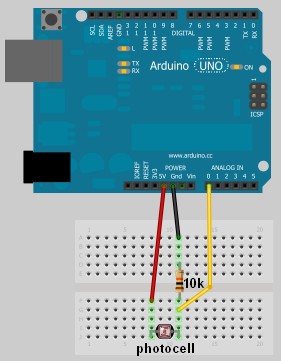
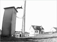
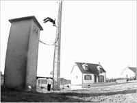
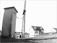
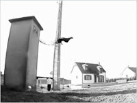
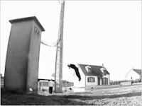
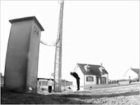
In this project, I have connected an Arduino to my computer and used a photoresistor to control an animation on the screen. Other sensors could have been used, but I chose a photoresistor because it feels like magic!!

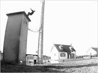
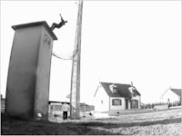
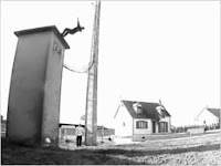
The photoresistor responds to changes in ambient light as my hand moves up and down. The Arduino sends the reading to a Processing sketch on the computer via a Serial command (through the USB cable). The processing sketch interprets the signal from the Arduino and selects the appropriate picture to display.

I took a series of screenshots from the following YouTube video: http://www.youtube.com/watch?v=h6nE8m74kDg  And after borrowing a bit of code from these sites (1,2), the project was born.
This idea is not new, nor my own. There are many people who have done this project before, but I thought to blog about how I have done it, just for fun.

The Project Movie


Components Required


  • Arduino Uno (and associated software), and USB cable
  • Photoresistor or Photocell
  • 10K resistor
  • Wires to put it all together
  • Processing IDE from http://processing.org
  • Computer/laptop


The Arduino Sketch


The Arduino Code:

You can download the Arduino IDE from this site.
 1
2
3
4
5
6
7
8
9
10
11
12
13
14
15
16
17
18
19
20
21
22
23
24
25
26
27
28
29
30
31
32
33
34
35
36
37
38
39
40
41
42
43
44
45
46
47
48
49
/* Jumper: Using an Arduino to animate:
Written by ScottC on 02/06/2012 */

int photoRPin = 0;
int minLight;
int maxLight;
int lightLevel;
int adjustedLightLevel;
int oldLightLevel;

void setup() {
Serial.begin(9600);

//Setup the starting light level limits
lightLevel=analogRead(photoRPin);
minLight=lightLevel-10;
maxLight=lightLevel;
oldLightLevel=lightLevel;
}

void loop(){
lightLevel=analogRead(photoRPin);
delay(10);

//auto-adjust the minimum and maximum limits in real time
if(minLight>lightLevel){
minLight=lightLevel;
}
if(maxLight<lightLevel){
maxLight=lightLevel;
}

//Map the light level to produce a result between 1 and 28.
adjustedLightLevel = map(lightLevel, (minLight+20), (maxLight-20), 1, 28);
adjustedLightLevel = constrain (adjustedLightLevel, 1,28);

/*Only send a new value to the Serial Port if the
adjustedLightLevel value changes.*/
if(oldLightLevel==adjustedLightLevel){
//do nothing if the old value and the new value are the same.
}else{
//Update the oldLightLevel value for the next round
oldLightLevel=adjustedLightLevel;

/*Send the adjusted Light level result
to Serial port (processing)*/
Serial.println(adjustedLightLevel);
}
}

The code above was formatted using this site.


The Processing Code:

You can download the Processing IDE from this site.

 1
2
3
4
5
6
7
8
9
10
11
12
13
14
15
16
17
18
19
20
21
22
23
24
25
26
27
28
29
30
31
32
33
34
35
36
37
38
39
40
41
42
43
44
45
46
47
48
49
50
51
52
53
54
55
56
57
58
59
60
61
62
63
64
65
66
67
68
69
70
71
72
73
74
75
76
77
/* Jumper: Using an Arduino to animate
Written by ScottC on 02/06/2012

Source code derived from :
http://processing.org/learning/topics/sequential.html
http://processing.org/discourse/beta/num_1267080062.html

Pictures captured from:
http://www.youtube.com/watch?v=h6nE8m74kDg

======================================================= */

import processing.serial.*;
Serial myPort;
String sensorReading="";

// Create the array that will hold the images
PImage[] movieImage = new PImage[29];

/* The frame variable is used to control which
image is displayed */
int frame = 1;


/* Setup the size of the window. Initialise serial communication with Arduino
and pre-load the images to be displayed later on. This is done only once.
I am using COM6 on my computer, you may need replace this value with your
active COM port being used by the Arduino.*/

void setup(){
size(700,600);

myPort = new Serial(this, "COM6", 9600);
myPort.bufferUntil('\n');

for(int i=0;i<28;i++){
movieImage[i] = loadImage("Jumper" + (i+1) + ".jpg");
}
}


// The draw function controls the animation sequence.

void draw(){

//this draws the relevant image to the window
image(movieImage[frame-1],0,0,width,height);
}

void serialEvent (Serial myPort){
sensorReading = myPort.readStringUntil('\n');
if(sensorReading != null){
sensorReading=trim(sensorReading);
if (sensorReading.length()<2){
frame = integerFromChar(sensorReading.charAt(0));
}else{
frame = integerFromChar(sensorReading.charAt(0))*10;
frame += integerFromChar(sensorReading.charAt(1));
}
}
}


/* This function used to convert the character received from the
serial port (Arduino), and converts it to a number */

int integerFromChar(char myChar) {
if (myChar < '0' || myChar > '9') {
return -1;
}else{
return myChar - '0';
}
}

The code above was formatted using this site.


The pictures 

Captured from this YouTube Video: http://www.youtube.com/watch?v=h6nE8m74kDg


n/a
Let's Make Robots 01 Jan 00:00
12  32  altoids  arduino  array  buttons  cable  cat5  cieling  computer  encoder  equalizer  foot  frequency  key  lcd  leds  lights  power  push  rca  register  rotary  screen  shift  supply  switch  tin  trigger  ultra  uv  violet  visualizer  wire