In this project, I have connected an Arduino to my computer and used a photoresistor to control an animation on the screen. Other sensors could have been used, but I chose a photoresistor because it feels like magic!!
The photoresistor responds to changes in ambient light as my hand moves up and down. The Arduino sends the reading to a Processing sketch on the computer via a Serial command (through the USB cable). The processing sketch interprets the signal from the Arduino and selects the appropriate picture to display.
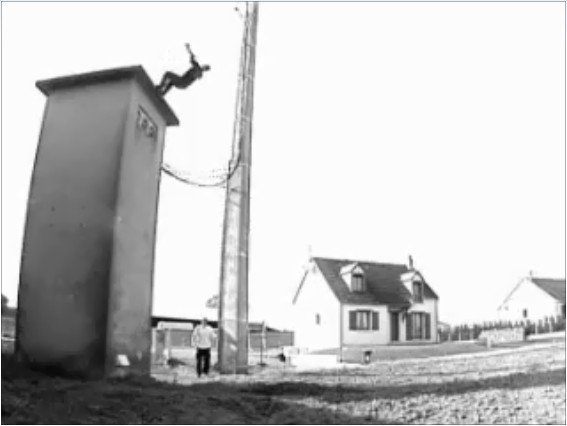
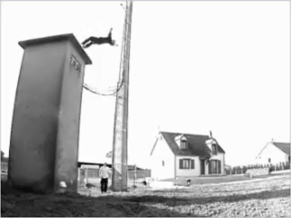
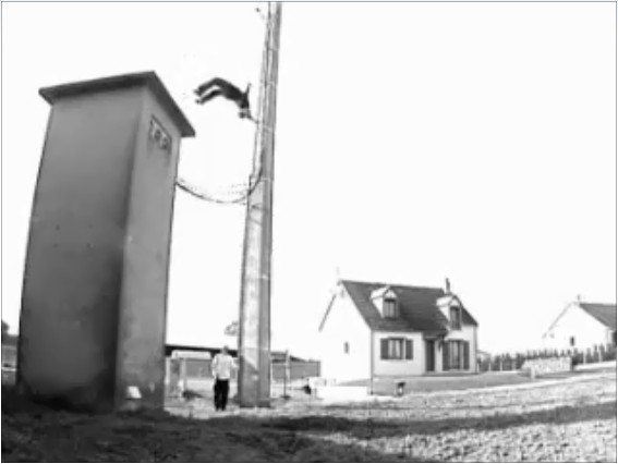
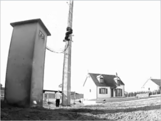
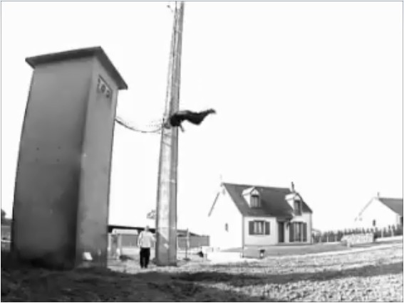
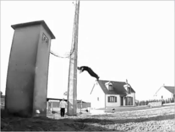
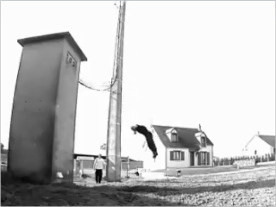
I took a series of screenshots from the following YouTube video:
http://www.youtube.com/watch?v=h6nE8m74kDg And after borrowing a bit of code from these sites (
1,
2), the project was born.
This idea is not new, nor my own. There are many people who have done this project before, but I thought to blog about how I have done it, just for fun.
The Project Movie
Components Required
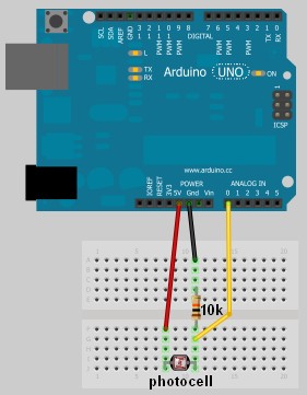
- Arduino Uno (and associated software), and USB cable
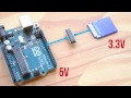
- Photoresistor or Photocell
- 10K resistor
- Wires to put it all together
- Processing IDE from http://processing.org
- Computer/laptop
The Arduino Sketch
The Arduino Code:
You can download the Arduino IDE from
this site.
 1
 2
 3
 4
 5
 6
 7
 8
 9
10
11
12
13
14
15
16
17
18
19
20
21
22
23
24
25
26
27
28
29
30
31
32
33
34
35
36
37
38
39
40
41
42
43
44
45
46
47
48
49 | /* Jumper: Using an Arduino to animate:
Written by ScottC on 02/06/2012 */
int photoRPin = 0;
int minLight;
int maxLight;
int lightLevel;
int adjustedLightLevel;
int oldLightLevel;
void setup() {
Serial.begin(9600);
//Setup the starting light level limits
lightLevel=analogRead(photoRPin);
minLight=lightLevel-10;
maxLight=lightLevel;
oldLightLevel=lightLevel;
}
void loop(){
lightLevel=analogRead(photoRPin);
delay(10);
//auto-adjust the minimum and maximum limits in real time
if(minLight>lightLevel){
minLight=lightLevel;
}
if(maxLight<lightLevel){
maxLight=lightLevel;
}
//Map the light level to produce a result between 1 and 28.
adjustedLightLevel = map(lightLevel, (minLight+20), (maxLight-20), 1, 28);
adjustedLightLevel = constrain (adjustedLightLevel, 1,28);
/*Only send a new value to the Serial Port if the
adjustedLightLevel value changes.*/
if(oldLightLevel==adjustedLightLevel){
//do nothing if the old value and the new value are the same.
}else{
//Update the oldLightLevel value for the next round
oldLightLevel=adjustedLightLevel;
/*Send the adjusted Light level result
to Serial port (processing)*/
Serial.println(adjustedLightLevel);
}
}
|
The Processing Code:
You can download the Processing IDE from
this site.
 1
 2
 3
 4
 5
 6
 7
 8
 9
10
11
12
13
14
15
16
17
18
19
20
21
22
23
24
25
26
27
28
29
30
31
32
33
34
35
36
37
38
39
40
41
42
43
44
45
46
47
48
49
50
51
52
53
54
55
56
57
58
59
60
61
62
63
64
65
66
67
68
69
70
71
72
73
74
75
76
77 | /* Jumper: Using an Arduino to animate
Written by ScottC on 02/06/2012
Source code derived from :
http://processing.org/learning/topics/sequential.html
http://processing.org/discourse/beta/num_1267080062.html
Pictures captured from:
http://www.youtube.com/watch?v=h6nE8m74kDg
======================================================= */
import processing.serial.*;
Serial myPort;
String sensorReading="";
// Create the array that will hold the images
PImage[] movieImage = new PImage[29];
/* The frame variable is used to control which
image is displayed */
int frame = 1;
/* Setup the size of the window. Initialise serial communication with Arduino
and pre-load the images to be displayed later on. This is done only once.
I am using COM6 on my computer, you may need replace this value with your
active COM port being used by the Arduino.*/
void setup(){
size(700,600);
myPort = new Serial(this, "COM6", 9600);
myPort.bufferUntil('\n');
for(int i=0;i<28;i++){
movieImage[i] = loadImage("Jumper" + (i+1) + ".jpg");
}
}
// The draw function controls the animation sequence.
void draw(){
//this draws the relevant image to the window
image(movieImage[frame-1],0,0,width,height);
}
void serialEvent (Serial myPort){
sensorReading = myPort.readStringUntil('\n');
if(sensorReading != null){
sensorReading=trim(sensorReading);
if (sensorReading.length()<2){
frame = integerFromChar(sensorReading.charAt(0));
}else{
frame = integerFromChar(sensorReading.charAt(0))*10;
frame += integerFromChar(sensorReading.charAt(1));
}
}
}
/* This function used to convert the character received from the
serial port (Arduino), and converts it to a number */
int integerFromChar(char myChar) {
if (myChar < '0' || myChar > '9') {
return -1;
}else{
return myChar - '0';
}
}
|
The pictures
Captured from this YouTube Video:
http://www.youtube.com/watch?v=h6nE8m74kDg


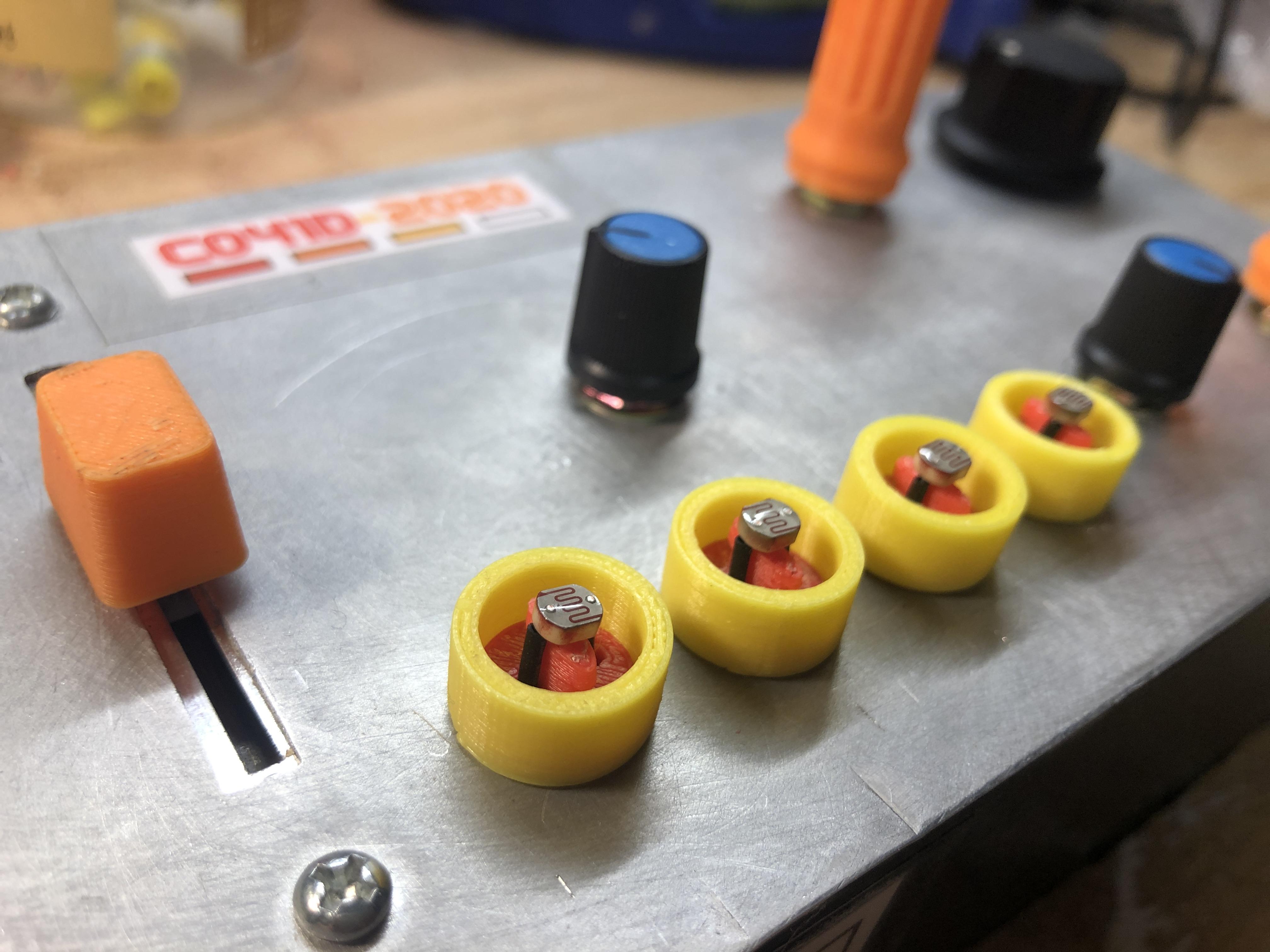 It works like this: either shine some light on the photocells, cover them up, or find some middle ground between the two. No matter what you do, you’re going to get cool sounds out of this thing.