Posts with «led display» label

1,156 LEDs make up these dual acrylic light-up panels

What does one do with over 1,000 LEDs, white acrylic, and 288 IR sensors? If you’re Redditor “jordy_essen,” you create an interactive light panel.

In one mode, the user pull a reflective tool across the sensors to draw a paths, with potentiometers implemented to select the color. It can also be set up to play a sort of whack-a-mole game, where one has to activate the sensor in the same area where it illuminates.

For this amazing device, jordy_essen uses not one, or even two, but six Arduino Mega boards to drive the LEDs directly — in turn controlled by a webpage running on a Raspberry Pi. If that wasn’t enough hardware, an Uno is tasked with taking inputs from the color potentiometers. 

It’s a brilliant project in any sense of the word!

Hundreds of LED triangles combine for brilliant interactive display

If you need another idea for how to creatively diffuse LED lighting, then look no further than the “Light Me Up!” project by Hyewon Shin, Eunjeong Ko, and Junsung Yi. 

Their setup uses 312 3D-printed and laser-cut light triangles, each of which contains a trio of RGB LEDs. Users select the desired light by pressing the triangles themselves, via buttons concealed beneath the main assembly. Several Arduino boards are used to control the massive structure.

With such an involved triangular display, a number of interesting 3D-like shapes and even words can be created by users. Alternatively, smaller triangle arrangements can also be constructed using the same build concepts. 

This project has several triangles that form a hexagonal shape. So you can create stereoscopic patterns according to how you design light! Just press each piece and various colors will be gradated, and when the color you want comes out, just hit the hand you pressed and it will continue to shine beautifully with the color you wanted!

Check out its triangular luminescence in the videos below!

Vintage LED display prototype revived with Arduino

Patrick Hickey has been collecting retro LED indicators and displays for decades, and his rarest item is an HP 5082-7002—a 5×7 dot matrix LED display in a beautiful gold and (possibly) sapphire enclosure. This device is so rare, in fact, that he believes it to be a prototype, somehow relegated to eBay for gold salvage.

Hickey wasn’t able to find any reference to the unit—much less a datasheet—even after extensive research. Instead, he went to work reverse engineering the HP 5082-7002 following the tracks of the PCB to work out how the rows and columns are connected. 

He then designed a test shield for an Arduino Uno with sockets on which the mystery device could sit. With this piece of hardware built, he can now create simple pictures and animated sprites on it using pulsed Arduino outputs.

I followed the tracks to work out which pins are connected rows and columns, and set out to build a test shield for an Arduino Uno.  I decided to drive them as “rows” of 5. The max output of Arduino I/O pins is rated at 40mA, so in theory, I could simultaneously power up to 5 LEDs in parallel at 8mA using 1 pin. In practice, using strobe/multiplexing, the duty cycle is much less: 1/7 or 1/5 depending if you drive by rows (7) or columns (5) respectively. The 5 current limiting series resistors are 470 Ohms (¼ Watt). My preference is to use carbon composition resistors (e.g. Allen Bradley). I love the “retro look” of them and I think they compliment the vintage LEDs.  

I had already written Arduino code for testing some TIL-305 matrix displays, so it was relatively simple to transpose the pins in my sketch for this configuration. The test code permits animations of up to 150 different alphanumeric characters/symbols, and (of course) some animated sprites inspired by retro video games.

Star Wars mouse droid reveals hidden scrolling LED display

In several iterations of the Star Wars saga, small black droids can be seen scurrying around imperial installations. While they tend to fade into the background or provide a fun distraction in the movies, the mouse droid by Potent Printables acts as a sort of physical messaging app. It’s able to travel to the correct location, then pop open to unveil a scrolling LED sign.

Potent Printables can trigger the side door using a Bluetooth app on his phone. On command, an RC servo pushes it open, and lowers it down using a stepper motor/reel setup. An Arduino Uno along with an Adafruit Motor Shield are used for control, while an HC-05 module enables communication with the system.  

Check out the latest video in this build series below!

An Arduino-powered backlit Clemson Tiger Paw

Most people support their school or favorite sports team by buying a shirt or tuning into games. Jacob Thompson, however, took things one step further and created his own Arduino-powered, backlit Clemson Tiger Paw.

Thompson’s “WallPaw,” as he calls it, uses an Arduino Uno to receive signals from an infrared remote and to pick up sounds with a small microphone. This information is passed on to an Arduino Mega, which controls a five-meter-long strip of WS2812 LEDs to provide lighting effects.

He notes that it would be possible to use only one Arduino board for everything, but patterned his code after this tutorial that included two. The paw itself is cut out of wood and clear acrylic, allowing the lights underneath to shine through nicely.

You can see the build in action below and find more details on Thompson’s website here.

Who on Earth Needs a Ninja Timer?

John Edgar Park builds a giant 7-segment display timer for a Ninja obstacle course.

Read more on MAKE

The post Who on Earth Needs a Ninja Timer? appeared first on Make: DIY Projects and Ideas for Makers.

Control an LED display with your electric guitar!

Have you ever wanted to have a light show that reacts to what you play through you’re favorite electric instrument? Georgia Tech grad student Wil Roberts has, and so he created a guitar-controlled LED display–an impressive project that combines both his Maker and musical chops.

To accomplish this, Roberts used an Arduino Uno along with an Adafruit 16×32 RGB LED matrix panel that responds to the guitar’s signal. The bottom rows are always blue, while the top ones progress from green to red the louder he shreds. The top rows remain red depending on the length of the note being played.

Want one of your own? Roberts has made all of the display’s circuitry and code available on Instructables. In the meantime, be sure to see it in action below!

New Project: 3D Print a Supersized Seven-Segment Clock

Building your own clock is practically a rite of passage as a Maker. 3D-print this Arduino-based desktop clock with a jumbo seven-segment LED display that glows from within.

Read more on MAKE

The post 3D Print a Supersized Seven-Segment Clock appeared first on Make: DIY Projects, How-Tos, Electronics, Crafts and Ideas for Makers.

10 seconds count down using Arduino

This is one of my 1st Arduino projects. Along with Arduino, I've used a seven segmeent led display and a piezzo buzzer. First, it beeps to indicate start. Then, counts down from 9 to 0, beeps three times. Finally, it beeps for the last time but this time the beep lasts longer.

Arduino Musical Note Recognition – Pushing the limits.

Second project based on Arduino Uno and FFT code.    (First one : Project 1.)
Short description ( EDITED: Project stopped. I lost my inspiration and working on visual recognition now, I decided to publish a code, so someone else could find it useful and continue research. ).

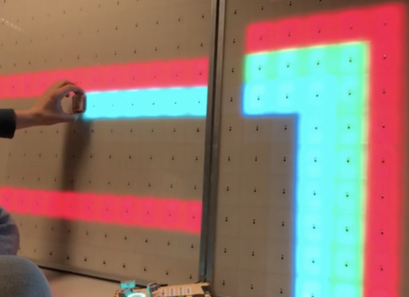
Main array size is 1024 bytes, real / imaginary 512 / 512, output 256 bins (only half real part, other half is mirror).  Sampling rate 4 kHz, upper note B6 (1975.5 Hz) on yellow line – right side led, lower note C3 (130.8 Hz) on red line – left side led.  Frequency resolution is approximately 7.8 Hz per bin. Processing and sampling are running in parallel. Sampling array size is 256. After data captured (256 x 0.25 msec = 64 msec) they transfered to processing array 1024, missing 256 real samples is “zero padded”, and sampling continue w/o interruption.  I did zero padding on a purpose to get “response time” of led matrix as fast as possible, so real-time 1/16 notes could be visually distinguished the same time,  as they played.

After computational cycle is completed (~36 msec), main program executes “cognitive core function” to differentiate between notes / tones, that have to be displayed on LED matrix.

 In order to minimize error rate of this process, Masking Shadow Theory (MST) was developed. Masking shadow for each note is calculated in several steps and result is compared with notes magnitude in the cycle. If magnitude is less than shadow, than led corresponding to this note wouldn’t  lights up. There are five steps for now, but as I say, work in progress. 
Step 1 (masking shadow 0):  noise floor, which is common for all notes. 
Step 2 (masking shadow 1):  shadow from neighboring notes, that includes 8   notes on left and right side, in inverse proportion to their distances. 
Step 3 (masking shadow 2):  shadow from the note, which is located 1 octave below. Or in other words, cross check if current bins value isn’t second harmonic from sounding note 1 octave below  it. 
Step 4 (masking shadow 3):  similar to step 3, the only difference is, cross check if current bin (note) isn’t third harmonic from sounding note below  it. 
Step 5 (masking shadow 5):  similar to step 3 and 4,  cross check if current note isn’t fifth harmonic from sounding note below  it.

Masking shadow is multiplied by notes specific coefficients after steps 3 – 5, to accommodate significantly richer spectral content for lower octaves.  Formula for calculation of the coefficients, is the trickiest   part of all project. What I’ve discovered, coefficient not just varying between notes / tones, they dynamically varying during “life-time” of the tone.

25 Sept. 2011 

There are two variables have been considered: speed, octave range. Third one, “not technical” – is a price for the project. 
 Octave range is defined by  RAM memory available on chip. 2K on UNO. As maximum processing array size is must be power of 2 ( FFT Radix-2 ), array couldn’t be more than  1024 bytes, next value – 2048 is size of all RAM, that obviously couldn’t be taken. Size of array defines maximum quantity of frequency bins at the output 1024 / 4 = 256. Divided by 4 as there is real / imaginary part, and only half real part is present data. What is interesting, that musical octave is nothing else than doubling of the tones frequency, so it follows binary arithmetic rules… If I will count from high side, the upper octave would occupied half of all 256 bins, from bin 256 to bin 128. Simply because frequency / musical tone spaced logarithmically (LOG_2), and bins spaced equally. Next octave takes half what left over, from bin 128 to bin 64. Third octave 64 to 32, and fourth 32 to 16. Can I go more down ? No. There are 12 notes in each octave. It means, that after fourth octave counting down , I arrived to location where bins and tones spaced almost in sequence, bin 16 – C3, bin 17 – C3#, bin 18 – D3. Well there is four more ( 15, 14, 13, and 12 ), but it doesn’t change much, as it only 1/3 of octave and only would complicate multiplexing LED display.
This is why variable octave range = 4. Summing up, increasing octave range by 1 ( to 5 octaves ) would require double memory size (2K processing array, still possible with chip 4K), by 2 ( to 6 octaves ) – four times more memory (4K processing array).

Arduino mega board has 8K RAM, would it be better to design project with it? In first, it cost more money. In second, it has the same CPU performance, and as you will see below, to have more memory w/o faster CPU doesn’t make any sense. CPU wouldn’t be able to process bigger volume of data in time.

Now lets have a look at speed variable. Following math (and design itself), is greatly depends on it. In order to get at least 1/16 note to be visually “alive”, all cycle ( sampling , pre-processing, FFT, post-processing ) has to be completed for less than 64 msec. My impression is, when timing a little bit longer, LED display looks like it shows something, that was played last Saturday night. Invisible real-time connection between “light” and “music” become broken.
Octave range variable ( 4 octave to be specific ), especially low notes starting from C3, begging for 8 Hz resolution, as it equals to distance between C3 and C3#. And consequently, for 128 msec sampling frame duration. So, there is a contradiction. To solved this , zero padding was introduced, which help to keep sampling window down to 64 msec, the same time frequency resolution not very far from 8 Hz. To make real-time life show, sampling must continue w/o interruption. Even more, it has to be “overlapped”, as pre-processing (windowing) would cut off beginning and ending of the sampling pull. All three other functions ( FFT, pre- and post-processing ) have to go in parallel and must be completed in the same time frame 64 msec. Arduino platform has 8-bit microprocessor, with low horse power engine under hood. This is why 8-bit math was selected instead of 16-bits ( which would save me a lot of troubles ). Troubles, I’m talking about, are very low dynamic range when integer math and 8 – bit comes together in FFT. Integer math, which gives nice time performance, puts really hard constrain on dynamic range, just because it performs “scaling” before and after every “butterfly”. And every scaling procedure brings in rounding error, which grows enormously, as there are 2304 butterfly (9216 round operation) for N = 512 FFT. Special attention must be payed, to keep rounding error under control, the same time not to increase calculation time too much or integer math would not make any sense. What I find out, there is  an excellent algorithm to make “symmetrical” 1/2 bit rounding, but it almost doubles calculation FFT timing, which I obviously, could not afford. So, I choose other path, to increase dynamic range. Compression algorithm on the input data. The easiest way to do it, is “clipping”. Set couple lines in the code:
             if ( x[i] >  127 )  x[i] =  127; 
             if ( x[i] < -127 )  x[i] = -127; 

and all good. Not quite. It will do a great job for any other signal (vibration from accelerometer for example), except music…..
Clipping generates a very high level of harmonics, and ones again , it couldn’t be afford, as it just undermine basic idea of the project – MUSICAL note recognition.
 
 Summary: Scaling extends dynamic range of integer FFT on 24 dB ( 4 bits ).

8- bit FFT dynamic range is +36 dB;
scaling                               +24 dB;
noise                                 -   3 dB;     
———————————————————–
Overall                                 57 dB.   


Link to download a scketch:


Arduino_Musical_Notes_Recognition