Posts with «freetronics» label

Experimenting with Arduino and IKEA DIODER LED Strips

Introduction

A few weeks ago I found a DIODER LED strip set from a long-ago trek to IKEA, and considered that something could be done with it.  So in this article you can see how easy it is to control the LEDs using an Arduino or compatible board with ease… opening it up to all sorts of possibilities.

This is not the most original project – however things have been pretty quiet around here, so I thought it was time to share something new with you. Furthermore the DIODER control PCB has changed, so this will be relevant to new purchases. Nevertheless, let’s get on with it.

So what is DIODER anyhow? 

As you can see in the image below, the DIODER pack includes four RGB LED units each with nine RGB LEDs per unit. A controller box allows power and colour choice, a distribution box connects between the controller box and the LED strips, and the whole thing is powered by a 12V DC plugpack:

The following is a quick video showing the DIODER in action as devised by IKEA:


Thankfully the plugpack keeps us away from mains voltages, and includes a long detachable cable which connects to the LED strip distribution box. The first thought was to investigate the controller, and you can open it with a standard screwdriver. Carefully pry away the long-side, as two clips on each side hold it together…


… which reveals the PCB. Nothing too exciting here – you can see the potentiometer used for changing the lighting effects, power and range buttons and so on:

Our DIODER has the updated PCB with the Chinese market microcontroller. If you have an older DIODER with a Microchip PIC – you can reprogram it yourself.

The following three MOSFETs are used to control the current to each of the red, green and blue LED circuits. These will be the key to controlling the DIODER’s strips – but are way too small for me to solder to. The original plan was to have an Arduino’s PWM outputs tap into the MOSFET’s gates – but instead I will use external MOSFETs.

So what’s a MOSFET?

In the past you may have used a transistor to switch higher current from an Arduino, however a MOSFET is a better solution for this function. The can control large voltages and high currents without any effort. We will use N-channel MOSFETs, which have three pins – Source, Drain and Gate. When the Gate is HIGH, current will flow into the Drain and out of the Gate:

A simplistic explanation is that it can be used like a button – and when wiring your own N-MOSFET a 10k resistor should be used between Gate and Drain to keep the Gate low when the Arduino output is set to LOW (just like de-bouncing a button). To learn more about MOSFETS – get yourself a copy of “The Art of Electronics“. It is worth every cent.

However being somewhat time poor (lazy?), I have instead used a Freetronics NDrive Shield for Arduino – which contains six N-MOSFETs all on one convenient shield  – with each MOSFET’s Gate pin connected to an Arduino PWM output.

So let’s head back to the LED strips for a moment, in order to determine how the LEDs are wired in the strip. Thanks to the manufacturer – the PCB has the markings as shown below:

They’re 12V LEDs in a common-anode configuration. How much current do they draw? Depends on how many strips you have connected together…

For the curious I measured each colour at each length, with the results in the following table:

So all four strips turned on, with all colours on – the strips will draw around 165 mA of current at 12V. Those blue LEDs are certainly thirsty.

Moving on, the next step is to connect the strips to the MOSFET shield. This is easy thanks to the cable included in the DIODER pack, just chop the white connector off as shown below:

By connecting an LED strip to the other end of the cable you can then determine which wire is common, and which are the cathodes for red, green and blue.

The plugpack included with the DIODER pack can be used to power the entire project, so you will need cut the DC plug (the plug that connects into the DIODER’s distribution box) off the lead, and use a multimeter to determine which wire is negative, and which is positive.

Connect the negative wire to the GND terminal on the shield, and the positive wire to the Vin terminal.  Then…

  • the red LED wire to the D3 terminal,
  • the green LED wire to the D9 terminal,
  • and the blue LED wire to the D10 terminal.

Finally, connect the 12V LED wire (anode) into the Vin terminal. Now double-check your wiring. Then check it again.

Testing

Now to run a test sketch to show the LED strip can easily be controlled. We’ll turn each colour on and off using PWM (Pulse-Width Modulation) – a neat way to control the brightness of each colour. The following sketch will pulse each colour in turn, and there’s also a blink function you can use.

// Controlling IKEA DIODER LED strips with Arduino and Freetronics NDRIVE N-MOSFET shield
// CC by-sa-nc John Boxall 2015 - tronixstuff.com 
// Components from tronixlabs.com

#define red 3
#define green 9
#define blue 10
#define delaya 2

void setup() 
{
  pinMode(red, OUTPUT);
  pinMode(green, OUTPUT);
  pinMode(blue, OUTPUT);
}

void blinkRGB()
{
  digitalWrite(red, HIGH);
  delay(1000);
  digitalWrite(red, LOW);
  digitalWrite(green, HIGH);
  delay(1000);
  digitalWrite(green, LOW);
  digitalWrite(blue, HIGH);
  delay(1000);
  digitalWrite(blue, LOW);
}

void pulseRed()
{
  for (int i=0; i<256; i++)
  {
    analogWrite(red,i);
    delay(delaya);
  }
  for (int i=255; i>=0; --i)
  {
    analogWrite(red,i);
    delay(delaya);
  }
}

void pulseGreen()
{
  for (int i=0; i<256; i++)
  {
    analogWrite(green,i);
    delay(delaya);
  }
  for (int i=255; i>=0; --i)
  {
    analogWrite(green,i);
    delay(delaya);
  }
}

void pulseBlue()
{
  for (int i=0; i<256; i++)
  {
    analogWrite(blue,i);
    delay(delaya);
  }
  for (int i=255; i>=0; --i)
  {
    analogWrite(blue,i);
    delay(delaya);
  }
}

void loop()
{
  pulseRed();
  pulseGreen();
  pulseBlue();
}

Success. And for the non-believers, watch the following video:

Better LED control

As always, there’s a better way of doing things and one example of LED control is the awesome FASTLED library by Daniel Garcia and others. Go and download it now – https://github.com/FastLED/FastLED. Apart from our simple LEDS, the FASTLED library is also great with WS2812B/Adafruit NeoPixels and others.

One excellent demonstration included with the library is the AnalogOutput sketch, which I have supplied below to work with our example hardware:

#include <FastLED.h>

// Example showing how to use FastLED color functions
// even when you're NOT using a "pixel-addressible" smart LED strip.
//
// This example is designed to control an "analog" RGB LED strip
// (or a single RGB LED) being driven by Arduino PWM output pins.
// So this code never calls FastLED.addLEDs() or FastLED.show().
//
// This example illustrates one way you can use just the portions 
// of FastLED that you need.  In this case, this code uses just the
// fast HSV color conversion code.
// 
// In this example, the RGB values are output on three separate
// 'analog' PWM pins, one for red, one for green, and one for blue.
 
#define REDPIN   3
#define GREENPIN 9
#define BLUEPIN  10

// showAnalogRGB: this is like FastLED.show(), but outputs on 
// analog PWM output pins instead of sending data to an intelligent,
// pixel-addressable LED strip.
// 
// This function takes the incoming RGB values and outputs the values
// on three analog PWM output pins to the r, g, and b values respectively.
void showAnalogRGB( const CRGB& rgb)
{
  analogWrite(REDPIN,   rgb.r );
  analogWrite(GREENPIN, rgb.g );
  analogWrite(BLUEPIN,  rgb.b );
}


// colorBars: flashes Red, then Green, then Blue, then Black.
// Helpful for diagnosing if you've mis-wired which is which.
void colorBars()
{
  showAnalogRGB( CRGB::Red );   delay(500);
  showAnalogRGB( CRGB::Green ); delay(500);
  showAnalogRGB( CRGB::Blue );  delay(500);
  showAnalogRGB( CRGB::Black ); delay(500);
}

void loop() 
{
  static uint8_t hue;
  hue = hue + 1;
  // Use FastLED automatic HSV->RGB conversion
  showAnalogRGB( CHSV( hue, 255, 255) );
  
  delay(20);
}


void setup() {
  pinMode(REDPIN,   OUTPUT);
  pinMode(GREENPIN, OUTPUT);
  pinMode(BLUEPIN,  OUTPUT);

  // Flash the "hello" color sequence: R, G, B, black.
  colorBars();
}

You can see this in action through the following video:

Conclusion

So if you have some IKEA LED strips, or anything else that requires more current than an Arduino’s output pin can offer – you can use MOSFETs to take over the current control and have fun. And finally a plug for my own store – tronixlabs.com – offering a growing range and Australia’s best value for supported hobbyist electronics from adafruit, DFRobot, Freetronics, Seeed Studio and much much more.

As always, have fun and keep checking into tronixstuff.com. Why not follow things on twitterGoogle+, subscribe  for email updates or RSS using the links on the right-hand column, or join our forum – dedicated to the projects and related items on this website.

The post Experimenting with Arduino and IKEA DIODER LED Strips appeared first on tronixstuff.

Experimenting with Arduino and IKEA DIODER LED Strips

Introduction

A few weeks ago I found a DIODER LED strip set from a long-ago trek to IKEA, and considered that something could be done with it.  So in this article you can see how easy it is to control the LEDs using an Arduino or compatible board with ease… opening it up to all sorts of possibilities.

This is not the most original project – however things have been pretty quiet around here, so I thought it was time to share something new with you. Furthermore the DIODER control PCB has changed, so this will be relevant to new purchases. Nevertheless, let’s get on with it.

So what is DIODER anyhow? 

As you can see in the image below, the DIODER pack includes four RGB LED units each with nine RGB LEDs per unit. A controller box allows power and colour choice, a distribution box connects between the controller box and the LED strips, and the whole thing is powered by a 12V DC plugpack:

The following is a quick video showing the DIODER in action as devised by IKEA:


Thankfully the plugpack keeps us away from mains voltages, and includes a long detachable cable which connects to the LED strip distribution box. The first thought was to investigate the controller, and you can open it with a standard screwdriver. Carefully pry away the long-side, as two clips on each side hold it together…


… which reveals the PCB. Nothing too exciting here – you can see the potentiometer used for changing the lighting effects, power and range buttons and so on:

Our DIODER has the updated PCB with the Chinese market microcontroller. If you have an older DIODER with a Microchip PIC – you can reprogram it yourself.

The following three MOSFETs are used to control the current to each of the red, green and blue LED circuits. These will be the key to controlling the DIODER’s strips – but are way too small for me to solder to. The original plan was to have an Arduino’s PWM outputs tap into the MOSFET’s gates – but instead I will use external MOSFETs.

So what’s a MOSFET?

In the past you may have used a transistor to switch higher current from an Arduino, however a MOSFET is a better solution for this function. The can control large voltages and high currents without any effort. We will use N-channel MOSFETs, which have three pins – Source, Drain and Gate. When the Gate is HIGH, current will flow into the Drain and out of the Source:

A simplistic explanation is that it can be used like a button – and when wiring your own N-MOSFET a 10k resistor should be used between Gate and Drain to keep the Gate low when the Arduino output is set to LOW (just like de-bouncing a button). To learn more about MOSFETS – get yourself a copy of “The Art of Electronics“. It is worth every cent.

However being somewhat time poor (lazy?), I have instead used a Freetronics NDrive Shield for Arduino – which contains six N-MOSFETs all on one convenient shield  – with each MOSFET’s Gate pin connected to an Arduino PWM output.

So let’s head back to the LED strips for a moment, in order to determine how the LEDs are wired in the strip. Thanks to the manufacturer – the PCB has the markings as shown below:

They’re 12V LEDs in a common-anode configuration. How much current do they draw? Depends on how many strips you have connected together…

For the curious I measured each colour at each length, with the results in the following table:

So all four strips turned on, with all colours on – the strips will draw around 165 mA of current at 12V. Those blue LEDs are certainly thirsty.

Moving on, the next step is to connect the strips to the MOSFET shield. This is easy thanks to the cable included in the DIODER pack, just chop the white connector off as shown below:

By connecting an LED strip to the other end of the cable you can then determine which wire is common, and which are the cathodes for red, green and blue.

The plugpack included with the DIODER pack can be used to power the entire project, so you will need cut the DC plug (the plug that connects into the DIODER’s distribution box) off the lead, and use a multimeter to determine which wire is negative, and which is positive.

Connect the negative wire to the GND terminal on the shield, and the positive wire to the Vin terminal.  Then…

  • the red LED wire to the D3 terminal,
  • the green LED wire to the D9 terminal,
  • and the blue LED wire to the D10 terminal.

Finally, connect the 12V LED wire (anode) into the Vin terminal. Now double-check your wiring. Then check it again.

Testing

Now to run a test sketch to show the LED strip can easily be controlled. We’ll turn each colour on and off using PWM (Pulse-Width Modulation) – a neat way to control the brightness of each colour. The following sketch will pulse each colour in turn, and there’s also a blink function you can use.

// Controlling IKEA DIODER LED strips with Arduino and Freetronics NDRIVE N-MOSFET shield
// CC by-sa-nc John Boxall 2015 - tronixstuff.com 
// Components from tronixlabs.com

#define red 3
#define green 9
#define blue 10
#define delaya 2

void setup() 
{
  pinMode(red, OUTPUT);
  pinMode(green, OUTPUT);
  pinMode(blue, OUTPUT);
}

void blinkRGB()
{
  digitalWrite(red, HIGH);
  delay(1000);
  digitalWrite(red, LOW);
  digitalWrite(green, HIGH);
  delay(1000);
  digitalWrite(green, LOW);
  digitalWrite(blue, HIGH);
  delay(1000);
  digitalWrite(blue, LOW);
}

void pulseRed()
{
  for (int i=0; i<256; i++)
  {
    analogWrite(red,i);
    delay(delaya);
  }
  for (int i=255; i>=0; --i)
  {
    analogWrite(red,i);
    delay(delaya);
  }
}

void pulseGreen()
{
  for (int i=0; i<256; i++)
  {
    analogWrite(green,i);
    delay(delaya);
  }
  for (int i=255; i>=0; --i)
  {
    analogWrite(green,i);
    delay(delaya);
  }
}

void pulseBlue()
{
  for (int i=0; i<256; i++)
  {
    analogWrite(blue,i);
    delay(delaya);
  }
  for (int i=255; i>=0; --i)
  {
    analogWrite(blue,i);
    delay(delaya);
  }
}

void loop()
{
  pulseRed();
  pulseGreen();
  pulseBlue();
}

Success. And for the non-believers, watch the following video:

Better LED control

As always, there’s a better way of doing things and one example of LED control is the awesome FASTLED library by Daniel Garcia and others. Go and download it now – https://github.com/FastLED/FastLED. Apart from our simple LEDS, the FASTLED library is also great with WS2812B/Adafruit NeoPixels and others.

One excellent demonstration included with the library is the AnalogOutput sketch, which I have supplied below to work with our example hardware:

#include <FastLED.h>

// Example showing how to use FastLED color functions
// even when you're NOT using a "pixel-addressible" smart LED strip.
//
// This example is designed to control an "analog" RGB LED strip
// (or a single RGB LED) being driven by Arduino PWM output pins.
// So this code never calls FastLED.addLEDs() or FastLED.show().
//
// This example illustrates one way you can use just the portions 
// of FastLED that you need.  In this case, this code uses just the
// fast HSV color conversion code.
// 
// In this example, the RGB values are output on three separate
// 'analog' PWM pins, one for red, one for green, and one for blue.
 
#define REDPIN   3
#define GREENPIN 9
#define BLUEPIN  10

// showAnalogRGB: this is like FastLED.show(), but outputs on 
// analog PWM output pins instead of sending data to an intelligent,
// pixel-addressable LED strip.
// 
// This function takes the incoming RGB values and outputs the values
// on three analog PWM output pins to the r, g, and b values respectively.
void showAnalogRGB( const CRGB& rgb)
{
  analogWrite(REDPIN,   rgb.r );
  analogWrite(GREENPIN, rgb.g );
  analogWrite(BLUEPIN,  rgb.b );
}


// colorBars: flashes Red, then Green, then Blue, then Black.
// Helpful for diagnosing if you've mis-wired which is which.
void colorBars()
{
  showAnalogRGB( CRGB::Red );   delay(500);
  showAnalogRGB( CRGB::Green ); delay(500);
  showAnalogRGB( CRGB::Blue );  delay(500);
  showAnalogRGB( CRGB::Black ); delay(500);
}

void loop() 
{
  static uint8_t hue;
  hue = hue + 1;
  // Use FastLED automatic HSV->RGB conversion
  showAnalogRGB( CHSV( hue, 255, 255) );
  
  delay(20);
}


void setup() {
  pinMode(REDPIN,   OUTPUT);
  pinMode(GREENPIN, OUTPUT);
  pinMode(BLUEPIN,  OUTPUT);

  // Flash the "hello" color sequence: R, G, B, black.
  colorBars();
}

You can see this in action through the following video:

Control using a mobile phone?

Yes – click here to learn how.

Conclusion

So if you have some IKEA LED strips, or anything else that requires more current than an Arduino’s output pin can offer – you can use MOSFETs to take over the current control and have fun. And finally a plug for my own store – tronixlabs.com – offering a growing range and Australia’s best value for supported hobbyist electronics from adafruit, DFRobot, Freetronics, Seeed Studio and much much more.

As always, have fun and keep checking into tronixstuff.com. Why not follow things on twitterGoogle+, subscribe  for email updates or RSS using the links on the right-hand column, or join our forum – dedicated to the projects and related items on this website.

Project – Arduino “Book Monster”

Introduction

Recently we saw a neat project by the people from Evil Mad Scientist – their “Peek-O-Book“, a neat take on a book with a shy monster inside, based on hardware from their Snap-O-Lantern kit. Not wanting to fork out for the postage to Australia we decided to make our own version, of which you can follow along.

This is a fun project that doesn’t require too much effort and has a lot of scope for customisation. There’s no right or wrong when making your own (or this one!) so just have fun with it.

Construction

First, you’ll need a book of some sort, something large enough to hide the electronics yet not too large to look “suspicious” – then cut the guts out to make enough space for the electronics. Then again it’s subjective, so get whatever works for you. Coincidentally we found some “dummy books” (not books for dummies) that were perfect for the job:

After spraying the inside with matt black paint, the inside is better suited for the “eyes in the dark” effect required for the project:

The “book” had a magnet and matching metal disk on the flap to aid with keep the cover shut, however this was removed as it will not allow for smooth opening with the servo.

The electronics are quite simple if you have some Arduino or other development board experience. Not sure about Arduino? You can use any microcontroller that can control a servo and some LEDs. We’re using a Freetronics LeoStick as it’s really small yet offers a full Arduino Leonardo-compatible experience, and a matching Protostick to run the wires and power from:

By fitting all the external wiring to the Protostick you can still use the main LeoStick for other projects if required. The power is from 4 x AA cells, with the voltage reduced with a 1n4004 diode:

And for the “eyes” of our monster – you can always add more if it isn’t too crowded in the book:

We’ll need a resistor as well for the LEDs. As LEDs are current driven you can connect two in series with a suitable dropping resistor which allows you to control both if required with one digital output pin. You can use the calculator here to help determine the right value for the resistor.

Finally a servo is required to push the lid of the book up and down. We used an inexpensive micro servo that’s available from Tronixlabs:

The chopsticks are cut down and used as an extension to the servo horn to give it more length:

Don’t forget to paint the arm black so it doesn’t stand out when in use. We had a lazy attack and mounted the servo on some LEGO bricks held in with super glue, but it works. Finally, here is the circuit schematic for our final example – we also added a power switch after the battery pack:

To recap  – this is a list of parts used:

After some delicate soldering the whole lot fits neatly in the box:

Arduino Sketch

The behaviour of your “book monster” comes down to your imagination. Experiment with the servo angles and speed to simulate the lid opening as if the monster is creeping up, or quickly for a “pop-up” surprise. And again with the LED eyes you can blink them and alter the brightness with PWM. Here’s a quick sketch to give you an idea:

int angle;
int d; // for delays
int ledPin = 9; // LEDs on digital pin 9

#include <Servo.h>
Servo myservo;

void setup()
{
  myservo.attach(4); // servo control pin on digital 4
  pinMode(9, OUTPUT); 
  randomSeed(analogRead(0));
  myservo.write(10);
  delay(5000);
}

void behaviour1()
{
  for (angle = 10; angle <=40; angle++)
  {
    myservo.write(angle);
    delay(50);
  }
  digitalWrite(ledPin, HIGH);
  delay(250);
  digitalWrite(ledPin, LOW);
  delay(250);  
  digitalWrite(ledPin, HIGH);
  delay(250);
  digitalWrite(ledPin, LOW);
  delay(250);    
  digitalWrite(ledPin, HIGH);
  delay(1000);
  digitalWrite(ledPin, LOW);
  delay(250);    
  digitalWrite(ledPin, HIGH);
  delay(1000);
  digitalWrite(ledPin, LOW);
  delay(250);    
  digitalWrite(ledPin, HIGH);
  delay(1000);
  digitalWrite(ledPin, LOW);
  delay(250);    
  for (angle = 40; angle >=10; --angle)
  {
    myservo.write(angle);
    delay(5);
  }
}

void loop()
{
  behaviour1();
  delay(random(60000));
}

You can watch our example unit in this video.

Frankly the entire project is subjective, so just do what you want.

Conclusion

Well that was fun, and I am sure this will entertain many people. A relative is a librarian so this will adorn a shelf and hopefully give the children a laugh. Once again, thanks to the people from Evil Mad Science for the inspiration for this project – so go and buy something from their interesting range of kits and so on.

And if you enjoyed this article, or want to introduce someone else to the interesting world of Arduino – check out my book (now in a third printing!) “Arduino Workshop”.

Have fun and keep checking into tronixstuff.com. Why not follow things on twitterGoogle+, subscribe  for email updates or RSS using the links on the right-hand column, or join our forum – dedicated to the projects and related items on this website. Sign up – it’s free, helpful to each other –  and we can all learn something.

The post Project – Arduino “Book Monster” appeared first on tronixstuff.

Arduino Tutorials – Chapter 16 – Ethernet

Learn how to connect your Arduino to the outside world via Ethernet

This is chapter sixteen of our huge Arduino tutorial seriesUpdated 06/12/2013

In this chapter we will introduce and examine the use of Ethernet networking with Arduino over local networks and the greater Internet. It will be assumed that you have a basic understanding of computer networking, such as the knowledge of how to connect computers to a hub/router with RJ45 cables, what an IP and MAC address is, and so on. Furthermore, here is a good quick rundown about Ethernet.

Getting Started

You will need an Arduino Uno or compatible board with an Ethernet shield that uses the W5100 Ethernet controller IC (pretty much all of them):

…or consider using a Freetronics EtherTen – as it has everything all on the one board, plus some extras:

Furthermore you will need to power the board via the external DC socket – the W5100 IC uses more current than the USB power can supply. A 9V 1A plug pack/wall wart will suffice. Finally it does get hot – so be careful not to touch the W5100 after extended use. In case you’re not sure – this is the W5100 IC:

Once you have your Ethernet-enabled Arduino, and have the external power connected – it’s a good idea to check it all works. Open the Arduino IDE and selectFile > Examples > Ethernet > Webserver. This loads a simple sketch which will display data gathered from the analogue inputs on a web browser. However don’t upload it yet, it needs a slight modification.

You need to specify the IP address of the Ethernet shield – which is done inside the sketch. This is simple, go to the line:

IPAddress ip(192,168,1, 177);

And alter it to match your own setup. For example, in my home the router’s IP address is 10.1.1.1, the printer is 10.1.1.50 and all PCs are below …50. So I will set my shield IP to 10.1.1.77 by altering the line to:

IPAddress ip(10,1,1,77);

You also have the opportunity to change your MAC address. Each piece of networking equipment has a unique serial number to identify itself over a network, and this is normall hard-programmed into the equipments’ firmware. However with Arduino we can define the MAC address ourselves.

If you are running more than one Ethernet shield on your network, ensure they have different MAC addresses by altering the hexadecimal values in the line:

byte mac[] = { 0xDE, 0xAD, 0xBE, 0xEF, 0xFE, 0xED };

However if you only have one shield just leave it be. There may be the very, very, statistically rare chance of having a MAC address the same as your existing hardware, so that would be another time to change it.

Once you have made your alterations, save and upload the sketch. Now open a web browser and navigate to the IP address you entered in the sketch, and you should be presented with something similar to the following:


What’s happening? The Arduino has been programmed to offer a simple web page with the values measured by the analogue inputs. You can refresh the browser to get updated values.

At this point – please note that the Ethernet shields use digital pins 10~13, so you can’t use those for anything else. Some Arduino Ethernet shields may also have a microSD card socket, which also uses another digital pin – so check with the documentation to find out which one.

Nevertheless, now that we can see the Ethernet shield is working we can move on to something more useful. Let’s dissect the previous example in a simple way, and see how we can distribute and display more interesting data over the network. For reference, all of the Ethernet-related functions are handled by the Ethernet Arduino library. If you examine the previous sketch we just used, the section that will be of interest is:

for (int analogChannel = 0; analogChannel < 6; analogChannel++) 
          {
            int sensorReading = analogRead(analogChannel);
            client.print("analog input ");
            client.print(analogChannel);
            client.print(" is ");
            client.print(sensorReading);
            client.println("<br />");       
          }
          client.println("</html>");

Hopefully this section of the sketch should be familiar – remember how we have used serial.print(); in the past when sending data to the serial monitor box? Well now we can do the same thing, but sending data from our Ethernet shield back to a web browser – on other words, a very basic type of web page.

However there is something you may or may not want to  learn in order to format the output in a readable format – HTML code. I am not a website developer (!) so will not delve into HTML too much.

However if you wish to serve up nicely formatted web pages with your Arduino and so on, here would be a good start. In the interests of simplicity, the following two functions will be the most useful:

client.print(" is ");

Client.print (); allows us to send text or data back to the web page. It works in the same way as serial.print(), so nothing new there. You can also specify the data type in the same way as with serial.print(). Naturally you can also use it to send data back as well. The other useful line is:
client.println("<br />");

which sends the HTML code back to the web browser telling it to start a new line. The part that actually causes the carriage return/new line is the <br /> which is an HTML code (or “tag”) for a new line. So if you are creating more elaborate web page displays, you can just insert other HTML tags in the client.print(); statement. If you want to learn more about HTML commands, here’s a good tutorial site. Finally – note that the sketch will only send the data when it has been requested, that is when it has received a request from the web browser.

Accessing your Arduino over the Internet

So far – so good. But what if you want to access your Arduino from outside the local network?

You will need a static IP address – that is, the IP address your internet service provider assigns to your connection needs to stay the same. If you don’t have a static IP, as long as you leave your modem/router permanently swiched on your IP shouldn’t change. However that isn’t an optimal solution.

If your ISP cannot offer you a static IP at all, you can still move forward with the project by using an organisation that offers a Dynamic DNS. These organisations offer you your own static IP host name (e.g. mojo.monkeynuts.com) instead of a number, keep track of your changing IP address and linking it to the new host name. From what I can gather, your modem needs to support (have an in-built client for…) these DDNS services. As an example, two companies are No-IP andDynDNS.com. Please note that I haven’t used those two, they are just offered as examples.

Now, to find your IP address… usually this can be found by logging into your router’s administration page – it is usually 192.168.0.1 but could be different. Check with your supplier or ISP if they supplied the hardware. For this example, if I enter 10.1.1.1 in a web browser, and after entering my modem administration password, the following screen is presented:

What you are looking for is your WAN IP address, as you can see in the image above. To keep the pranksters away, I have blacked out some of my address.

The next thing to do is turn on port-forwarding. This tells the router where to redirect incoming requests from the outside world. When the modem receives such a request, we want to send that request to the port number of our Ethernet shield. Using the:

EthernetServer server(125);

function in our sketch has set the port number to 125. Each modem’s configuration screen will look different, but as an example here is one:

So you can see from the line number one in the image above, the inbound port numbers have been set to 125, and the IP address of the Ethernet shield has been set to 10.1.1.77 – the same as in the sketch.

After saving the settings, we’re all set. The external address of my Ethernet shield will be the WAN:125, so to access the Arduino I will type my WAN address with :125 at the end into the browser of the remote web device, which will contact the lonely Ethernet hardware back home.

Furthermore, you may need to alter your modem’s firewall settings, to allow the port 125 to be “open” to incoming requests. Please check your modem documentation for more information on how to do this.

Now from basically any Internet connected device in the free world, I can enter my WAN and port number into the URL field and receive the results. For example, from a phone when it is connected to the Internet via LTE mobile data:

So at this stage you can now display data on a simple web page created by your Arduino and access it from anywhere with unrestricted Internet access. With your previous Arduino knowledge (well, this is chapter sixteen) you can now use data from sensors or other parts of a sketch and display it for retrieval.

Displaying sensor data on a web page

As an example of displaying sensor data on a web page, let’s use an inexpensive and popular temperature and humidity sensor – the DHT22. You will need to install the DHT22 Arduino library which can be found on this page. If this is your first time with the DHT22, experiment with the example sketch that’s included with the library so you understand how it works.

Connect the DHT22 with the data pin to Arduino D2, Vin to the 5V pin and GND to … GND:

Now for our sketch – to display the temperature and humidity on a web page. If you’re not up on HTML you can use online services such as this to generate the code, which you can then modify to use in the sketch.

In the example below, the temperature and humidity data from the DHT22 is served in a simple web page:

#include <SPI.h>
#include <Ethernet.h>

// for DHT22 sensor
#include "DHT.h"
#define DHTPIN 2
#define DHTTYPE DHT22

// Enter a MAC address and IP address for your controller below.
// The IP address will be dependent on your local network:
byte mac[] = {   0xDE, 0xAD, 0xBE, 0xEF, 0xFE, 0xED };
IPAddress ip(10,1,1,77);

// Initialize the Ethernet server library
// with the IP address and port you want to use 
// (port 80 is default for HTTP):
EthernetServer server(125);
DHT dht(DHTPIN, DHTTYPE);

void setup() 
{
  dht.begin();
 // Open serial communications and wait for port to open:
  Serial.begin(9600);
   while (!Serial) {
    ; // wait for serial port to connect. Needed for Leonardo only
  }
  // start the Ethernet connection and the server:
  Ethernet.begin(mac, ip);
  server.begin();
  Serial.print("server is at ");
  Serial.println(Ethernet.localIP());
}

void loop() 
{
  // listen for incoming clients
  EthernetClient client = server.available();
  if (client) {
    Serial.println("new client");
    // an http request ends with a blank line
    boolean currentLineIsBlank = true;
    while (client.connected()) {
      if (client.available()) {
        char c = client.read();
        Serial.write(c);
        // if you've gotten to the end of the line (received a newline
        // character) and the line is blank, the http request has ended,
        // so you can send a reply
        if (c == '\n' && currentLineIsBlank) 
        {
          // send a standard http response header
          client.println("HTTP/1.1 200 OK");
          client.println("Content-Type: text/html");
          client.println("Connection: close");  // the connection will be closed after completion of the response
	  client.println("Refresh: 30");  // refresh the page automatically every 30 sec
          client.println();
          client.println("<!DOCTYPE HTML>");
          client.println("<html>");

          // get data from DHT22 sensor
          float h = dht.readHumidity();
          float t = dht.readTemperature();
          Serial.println(t);
          Serial.println(h);

          // from here we can enter our own HTML code to create the web page
          client.print("<head><title>Office Weather</title></head><body><h1>Office Temperature</h1><p>Temperature - ");
          client.print(t);
          client.print(" degrees Celsius</p>");
          client.print("<p>Humidity - ");
          client.print(h);
          client.print(" percent</p>");
          client.print("<p><em>Page refreshes every 30 seconds.</em></p></body></html>");
          break;
        }
        if (c == '\n') {
          // you're starting a new line
          currentLineIsBlank = true;
        } 
        else if (c != '\r') {
          // you've gotten a character on the current line
          currentLineIsBlank = false;
        }
      }
    }
    // give the web browser time to receive the data
    delay(1);
    // close the connection:
    client.stop();
    Serial.println("client disonnected");
  }
}

It is a modification of the IDE’s webserver example sketch that we used previously – with a few modifications. First, the webpage will automatically refresh every 30 seconds – this parameter is set in the line:

client.println("Refresh: 30");  // refresh the page automatically every 30 sec

… and the custom HTML for our web page starts below the line:

// from here we can enter our own HTML code to create the web page

You can then simply insert the required HTML inside client.print() functions to create the layout you need.

Finally – here’s an example screen shot of the example sketch at work:

You now have the framework to create your own web pages that can display various data processed with your Arduino.

Remote control your Arduino from afar

We have a separate tutorial on this topic, that uses the teleduino system.

Conclusion

So there you have it, another useful way to have your Arduino interact with the outside world. Stay tuned for upcoming Arduino tutorials by subscribing to the blog, RSS feed (top-right), twitter or joining our Google Group. And if you enjoyed the tutorial, or want to introduce someone else to the interesting world of Arduino – check out my book (now in a third printing!) “Arduino Workshop” from No Starch Press.

The post Arduino Tutorials – Chapter 16 – Ethernet appeared first on tronixstuff.

Arduino Tutorials – Chapter 16 – Ethernet

Learn how to connect your Arduino to the outside world via Ethernet

This is chapter sixteen of our huge Arduino tutorial seriesUpdated 06/12/2013

In this chapter we will introduce and examine the use of Ethernet networking with Arduino over local networks and the greater Internet. It will be assumed that you have a basic understanding of computer networking, such as the knowledge of how to connect computers to a hub/router with RJ45 cables, what an IP and MAC address is, and so on. Furthermore, here is a good quick rundown about Ethernet.

Getting Started

You will need an Arduino Uno or compatible board with an Ethernet shield that uses the W5100 Ethernet controller IC (pretty much all of them):

…or consider using a Freetronics EtherTen – as it has everything all on the one board, plus some extras:

Furthermore you will need to power the board via the external DC socket – the W5100 IC uses more current than the USB power can supply. A 9V 1A plug pack/wall wart will suffice. Finally it does get hot – so be careful not to touch the W5100 after extended use. In case you’re not sure – this is the W5100 IC:

Once you have your Ethernet-enabled Arduino, and have the external power connected – it’s a good idea to check it all works. Open the Arduino IDE and selectFile > Examples > Ethernet > Webserver. This loads a simple sketch which will display data gathered from the analogue inputs on a web browser. However don’t upload it yet, it needs a slight modification.

You need to specify the IP address of the Ethernet shield – which is done inside the sketch. This is simple, go to the line:

IPAddress ip(192,168,1, 177);

And alter it to match your own setup. For example, in my home the router’s IP address is 10.1.1.1, the printer is 10.1.1.50 and all PCs are below …50. So I will set my shield IP to 10.1.1.77 by altering the line to:

IPAddress ip(10,1,1,77);

You also have the opportunity to change your MAC address. Each piece of networking equipment has a unique serial number to identify itself over a network, and this is normall hard-programmed into the equipments’ firmware. However with Arduino we can define the MAC address ourselves.

If you are running more than one Ethernet shield on your network, ensure they have different MAC addresses by altering the hexadecimal values in the line:

byte mac[] = { 0xDE, 0xAD, 0xBE, 0xEF, 0xFE, 0xED };

However if you only have one shield just leave it be. There may be the very, very, statistically rare chance of having a MAC address the same as your existing hardware, so that would be another time to change it.

Once you have made your alterations, save and upload the sketch. Now open a web browser and navigate to the IP address you entered in the sketch, and you should be presented with something similar to the following:


What’s happening? The Arduino has been programmed to offer a simple web page with the values measured by the analogue inputs. You can refresh the browser to get updated values.

At this point – please note that the Ethernet shields use digital pins 10~13, so you can’t use those for anything else. Some Arduino Ethernet shields may also have a microSD card socket, which also uses another digital pin – so check with the documentation to find out which one.

Nevertheless, now that we can see the Ethernet shield is working we can move on to something more useful. Let’s dissect the previous example in a simple way, and see how we can distribute and display more interesting data over the network. For reference, all of the Ethernet-related functions are handled by the Ethernet Arduino library. If you examine the previous sketch we just used, the section that will be of interest is:

 for (int analogChannel = 0; analogChannel < 6; analogChannel++) 
          {
            int sensorReading = analogRead(analogChannel);
            client.print("analog input ");
            client.print(analogChannel);
            client.print(" is ");
            client.print(sensorReading);
            client.println("<br />");       
          }
          client.println("</html>");

Hopefully this section of the sketch should be familiar – remember how we have used serial.print(); in the past when sending data to the serial monitor box? Well now we can do the same thing, but sending data from our Ethernet shield back to a web browser – on other words, a very basic type of web page.

However there is something you may or may not want to  learn in order to format the output in a readable format – HTML code. I am not a website developer (!) so will not delve into HTML too much.

However if you wish to serve up nicely formatted web pages with your Arduino and so on, here would be a good start. In the interests of simplicity, the following two functions will be the most useful:

client.print(" is ");

Client.print (); allows us to send text or data back to the web page. It works in the same way as serial.print(), so nothing new there. You can also specify the data type in the same way as with serial.print(). Naturally you can also use it to send data back as well. The other useful line is:

client.println("<br />");

which sends the HTML code back to the web browser telling it to start a new line. The part that actually causes the carriage return/new line is the <br /> which is an HTML code (or “tag”) for a new line. So if you are creating more elaborate web page displays, you can just insert other HTML tags in the client.print(); statement. If you want to learn more about HTML commands, here’s a good tutorial site. Finally – note that the sketch will only send the data when it has been requested, that is when it has received a request from the web browser.

Accessing your Arduino over the Internet

So far – so good. But what if you want to access your Arduino from outside the local network?

You will need a static IP address – that is, the IP address your internet service provider assigns to your connection needs to stay the same. If you don’t have a static IP, as long as you leave your modem/router permanently swiched on your IP shouldn’t change. However that isn’t an optimal solution.

If your ISP cannot offer you a static IP at all, you can still move forward with the project by using an organisation that offers a Dynamic DNS. These organisations offer you your own static IP host name (e.g. mojo.monkeynuts.com) instead of a number, keep track of your changing IP address and linking it to the new host name. From what I can gather, your modem needs to support (have an in-built client for…) these DDNS services. As an example, two companies are No-IP andDynDNS.com. Please note that I haven’t used those two, they are just offered as examples.

Now, to find your IP address… usually this can be found by logging into your router’s administration page – it is usually 192.168.0.1 but could be different. Check with your supplier or ISP if they supplied the hardware. For this example, if I enter 10.1.1.1 in a web browser, and after entering my modem administration password, the following screen is presented:

What you are looking for is your WAN IP address, as you can see in the image above. To keep the pranksters away, I have blacked out some of my address.

The next thing to do is turn on port-forwarding. This tells the router where to redirect incoming requests from the outside world. When the modem receives such a request, we want to send that request to the port number of our Ethernet shield. Using the:

EthernetServer server(125);

function in our sketch has set the port number to 125. Each modem’s configuration screen will look different, but as an example here is one:

So you can see from the line number one in the image above, the inbound port numbers have been set to 125, and the IP address of the Ethernet shield has been set to 10.1.1.77 – the same as in the sketch.

After saving the settings, we’re all set. The external address of my Ethernet shield will be the WAN:125, so to access the Arduino I will type my WAN address with :125 at the end into the browser of the remote web device, which will contact the lonely Ethernet hardware back home.

Furthermore, you may need to alter your modem’s firewall settings, to allow the port 125 to be “open” to incoming requests. Please check your modem documentation for more information on how to do this.

Now from basically any Internet connected device in the free world, I can enter my WAN and port number into the URL field and receive the results. For example, from a phone when it is connected to the Internet via LTE mobile data:

So at this stage you can now display data on a simple web page created by your Arduino and access it from anywhere with unrestricted Internet access. With your previous Arduino knowledge (well, this is chapter sixteen) you can now use data from sensors or other parts of a sketch and display it for retrieval.

Displaying sensor data on a web page

As an example of displaying sensor data on a web page, let’s use an inexpensive and popular temperature and humidity sensor – the DHT22. You will need to install the DHT22 Arduino library which can be found on this page. If this is your first time with the DHT22, experiment with the example sketch that’s included with the library so you understand how it works.

Connect the DHT22 with the data pin to Arduino D2, Vin to the 5V pin and GND to … GND:

Now for our sketch – to display the temperature and humidity on a web page. If you’re not up on HTML you can use online services such as this to generate the code, which you can then modify to use in the sketch.

In the example below, the temperature and humidity data from the DHT22 is served in a simple web page:

#include <SPI.h>
#include <Ethernet.h>

// for DHT22 sensor
#include "DHT.h"
#define DHTPIN 2
#define DHTTYPE DHT22

// Enter a MAC address and IP address for your controller below.
// The IP address will be dependent on your local network:
byte mac[] = {   0xDE, 0xAD, 0xBE, 0xEF, 0xFE, 0xED };
IPAddress ip(10,1,1,77);

// Initialize the Ethernet server library
// with the IP address and port you want to use 
// (port 80 is default for HTTP):
EthernetServer server(125);
DHT dht(DHTPIN, DHTTYPE);

void setup() 
{
  dht.begin();
 // Open serial communications and wait for port to open:
  Serial.begin(9600);
   while (!Serial) {
    ; // wait for serial port to connect. Needed for Leonardo only
  }
  // start the Ethernet connection and the server:
  Ethernet.begin(mac, ip);
  server.begin();
  Serial.print("server is at ");
  Serial.println(Ethernet.localIP());
}

void loop() 
{
  // listen for incoming clients
  EthernetClient client = server.available();
  if (client) {
    Serial.println("new client");
    // an http request ends with a blank line
    boolean currentLineIsBlank = true;
    while (client.connected()) {
      if (client.available()) {
        char c = client.read();
        Serial.write(c);
        // if you've gotten to the end of the line (received a newline
        // character) and the line is blank, the http request has ended,
        // so you can send a reply
        if (c == 'n' && currentLineIsBlank) 
        {
          // send a standard http response header
          client.println("HTTP/1.1 200 OK");
          client.println("Content-Type: text/html");
          client.println("Connection: close");  // the connection will be closed after completion of the response
	  client.println("Refresh: 30");  // refresh the page automatically every 30 sec
          client.println();
          client.println("<!DOCTYPE HTML>");
          client.println("<html>");

          // get data from DHT22 sensor
          float h = dht.readHumidity();
          float t = dht.readTemperature();
          Serial.println(t);
          Serial.println(h);

          // from here we can enter our own HTML code to create the web page
          client.print("<head><title>Office Weather</title></head><body><h1>Office Temperature</h1><p>Temperature - ");
          client.print(t);
          client.print(" degrees Celsius</p>");
          client.print("<p>Humidity - ");
          client.print(h);
          client.print(" percent</p>");
          client.print("<p><em>Page refreshes every 30 seconds.</em></p></body></html>");
          break;
        }
        if (c == 'n') {
          // you're starting a new line
          currentLineIsBlank = true;
        } 
        else if (c != 'r') {
          // you've gotten a character on the current line
          currentLineIsBlank = false;
        }
      }
    }
    // give the web browser time to receive the data
    delay(1);
    // close the connection:
    client.stop();
    Serial.println("client disonnected");
  }
}

It is a modification of the IDE’s webserver example sketch that we used previously – with a few modifications. First, the webpage will automatically refresh every 30 seconds – this parameter is set in the line:

client.println("Refresh: 30");  // refresh the page automatically every 30 sec

… and the custom HTML for our web page starts below the line:

// from here we can enter our own HTML code to create the web page

You can then simply insert the required HTML inside client.print() functions to create the layout you need.

Finally – here’s an example screen shot of the example sketch at work:

You now have the framework to create your own web pages that can display various data processed with your Arduino.

Remote control your Arduino from afar

We have a separate tutorial on this topic, that uses the teleduino system.

Conclusion

So there you have it, another useful way to have your Arduino interact with the outside world. Stay tuned for upcoming Arduino tutorials by subscribing to the blog, RSS feed (top-right), twitter or joining our Google Group. And if you enjoyed the tutorial, or want to introduce someone else to the interesting world of Arduino – check out my book (now in a third printing!) “Arduino Workshop” from No Starch Press.

Project – LED Cube Spectrum Analyzer

Introduction

A few weeks ago I was asked about creating a musical-effect display with an RGB LED cube kit from Freetronics, and with a little work this was certainly possible using the MSGEQ7 spectrum analyser IC. In this project we’ll create a small add-on PCB containing the spectrum analyser circuit and show how it can drive the RGB LED cube kit.

Assumed knowledge

To save repeating myself, please familiarise yourself with the MSGEQ7 spectrum aanalyserIC in Chapter 48 of our Arduino tutorials. And learn more about the LED cube from our review and the product page.

You can get MSGEQ7 ICs from various sources, however they had varying results. We now recommend using the neat module from Tronixlabs.

The circuit

The LED cube already has an Arduino Leonardo-compatible built in to the main PCB, so all you need to do is build a small circuit that contains the spectrum analyzer which connects to the I/O pins on the cube PCB and also has audio input and output connections. First, consider the schematic:

For the purposes of this project our spectrum analyser will only display the results from one channel of audio – if you want stereo, you’ll need two! And note that the strobe, reset and DCOUT pins on the MSGEQ7 are labelled with the connections to the cube PCB. Furthermore the pinouts for the MSGEQ7 don’t match the physical reality – here are the pinouts from the MSGEQ7 data sheet (.pdf):

The circuit itself will be quite small and fit on a small amount of stripboard or veroboard. There is plenty of room underneath the cube to fit the circuit if so desired:

With a few moments you should be able to trace out your circuit to match the board type you have, remember to double-check before soldering. You will also need to connect the audio in point after the 1000 pF capacitor to a source of audio, and also pass it through so you can connect powered speakers, headphones, etc.

One method of doing so would be to cut up a male-female audio extension lead, and connect the shield to the GND of the circuit, and the signal line to the audio input on the circuit. Or if you have the parts handy and some shielded cable, just make your own input and output leads:

Be sure to test for shorts between the signal and shield before soldering to the circuit board. When finished, you should have something neat that you can hide under the cube or elsewhere:

Double-check your soldering for shorts and your board plan, then fit to the cube along with the audio source and speakers (etc).

Arduino Sketch

The sketch has two main functions – the first is to capture the levels from the MSGEQ7 and put the values for each frequency band into an array, and the second function is to turn on LEDs that represent the level for each band. If you’ve been paying attention you may be wondering how we can represent seven frequency bands with a 4x4x4 LED cube. Simple – by rotating the cube 45 degrees you can see seven vertical columns of LEDs:

So when looking from the angle as shown above, you have seven vertical columns, each with four levels of LEDs. Thus the strength of each frequency can be broken down into four levels, and then the appropriate LEDs turned on.

After this is done for each band, all the LEDs are turned off and the process repeats. For the sake of simplicity I’ve used the cube’s Arduino library to activate the LEDs, which also makes the sketch easier to fathom. The first example sketch only uses one colour:

// Freetronics CUBE4: and MSGEQ7 spectrum analyser
// MSGEQ7 strobe on A4, reset on D5, signal into A0

#include "SPI.h"
#include "Cube.h"
Cube cube;

int res = 5; // reset pins on D5
int left[7]; // store band values in these arrays
int band;

void setup()
{
  pinMode(res, OUTPUT); // reset
  pinMode(A4, OUTPUT); // strobe
  digitalWrite(res,LOW); 
  digitalWrite(A4,HIGH); 
  cube.begin(-1, 115200);
  Serial.begin(9600);
}

void readMSGEQ7()
// Function to read 7 band equalizers
{
  digitalWrite(res, HIGH);
  digitalWrite(res, LOW);
  for(band=0; band <7; band++)
  {
    digitalWrite(A4,LOW); // strobe pin on the shield - kicks the IC up to the next band 
    delayMicroseconds(30); // 
    left[band] = analogRead(0); // store band reading
    digitalWrite(A4,HIGH); 
  }
}

void loop()
{
  readMSGEQ7();

  for (band = 0; band < 7; band++)
  {
    // div each band strength into four layers, each band then one of the odd diagonals 

    // band one ~ 63 Hz
    if (left[0]>=768) { 
      cube.set(3,3,3, BLUE); 
    } 
    else       
      if (left[0]>=512) { 
      cube.set(3,3,2, BLUE); 
    } 
    else   
      if (left[0]>=256) { 
      cube.set(3,3,1, BLUE); 
    } 
    else       
      if (left[0]>=0) { 
      cube.set(3,3,0, BLUE); 
    } 

    // band two ~ 160 Hz
    if (left[1]>=768) 
    { 
      cube.set(3,2,3, BLUE); 
      cube.set(2,3,3, BLUE);      
    }  
    else
      if (left[1]>=512) 
      { 
        cube.set(3,2,2, BLUE); 
        cube.set(2,3,2, BLUE);      
      } 
      else   
        if (left[1]>=256) 
      { 
        cube.set(3,2,1, BLUE); 
        cube.set(2,3,1, BLUE);      
      } 
      else   
        if (left[1]>=0) 
      { 
        cube.set(3,2,0, BLUE); 
        cube.set(2,3,0, BLUE);      
      } 

    // band three ~ 400 Hz
    if (left[2]>=768) 
    { 
      cube.set(3,1,3, BLUE); 
      cube.set(2,2,3, BLUE);      
      cube.set(1,3,3, BLUE);            
    }  
    else
      if (left[2]>=512) 
      { 
        cube.set(3,1,2, BLUE); 
        cube.set(2,2,2, BLUE);      
        cube.set(1,3,2, BLUE);            
      } 
      else   
        if (left[2]>=256) 
      { 
        cube.set(3,1,1, BLUE); 
        cube.set(2,2,1, BLUE);      
        cube.set(1,3,1, BLUE);            
      } 
      else   
        if (left[2]>=0) 
      { 
        cube.set(3,1,0, BLUE); 
        cube.set(2,2,0, BLUE);      
        cube.set(1,3,0, BLUE);            
      } 

    // band four ~ 1 kHz
    if (left[3]>=768) 
    { 
      cube.set(3,0,3, BLUE); 
      cube.set(2,1,3, BLUE);      
      cube.set(1,2,3, BLUE);            
      cube.set(0,3,3, BLUE);                  
    }  
    else
      if (left[3]>=512) 
      { 
        cube.set(3,0,2, BLUE); 
        cube.set(2,1,2, BLUE);      
        cube.set(1,2,2, BLUE);            
        cube.set(0,3,2, BLUE);                        
      } 
      else   
        if (left[3]>=256) 
      { 
        cube.set(3,0,1, BLUE); 
        cube.set(2,1,1, BLUE);      
        cube.set(1,2,1, BLUE);      
        cube.set(0,3,1, BLUE);                        
      } 
      else   
        if (left[3]>=0) 
      { 
        cube.set(3,0,0, BLUE); 
        cube.set(2,1,0, BLUE);      
        cube.set(1,2,0, BLUE);            
        cube.set(0,3,0, BLUE);                        
      } 

    // band five  ~ 2.5 kHz
    if (left[4]>=768) 
    { 
      cube.set(2,0,3, BLUE); 
      cube.set(1,1,3, BLUE);      
      cube.set(0,2,3, BLUE);            
    }  
    else
      if (left[4]>=512) 
      { 
        cube.set(2,0,2, BLUE); 
        cube.set(1,1,2, BLUE);      
        cube.set(0,2,2, BLUE);            
      } 
      else   
        if (left[4]>=256) 
      { 
        cube.set(2,0,1, BLUE); 
        cube.set(1,1,1, BLUE);      
        cube.set(0,2,1, BLUE);      
      } 
      else   
        if (left[4]>=0) 
      { 
        cube.set(2,0,0, BLUE); 
        cube.set(1,1,0, BLUE);      
        cube.set(0,2,0, BLUE);            
      } 

    // band six   ~ 6.25 kHz
    if (left[5]>=768) 
    { 
      cube.set(1,0,3, BLUE); 
      cube.set(0,1,3, BLUE);      
    }  
    else
      if (left[5]>=512) 
      { 
        cube.set(1,0,2, BLUE); 
        cube.set(0,1,2, BLUE);      
      } 
      else   
        if (left[5]>=256) 
      { 
        cube.set(1,0,1, BLUE); 
        cube.set(0,1,1, BLUE);      
      } 
      else   
        if (left[5]>=0) 
      { 
        cube.set(1,0,0, BLUE); 
        cube.set(0,1,0, BLUE);      
      } 

    // band seven  ~ 16 kHz
    if (left[6]>=768) 
    { 
      cube.set(0,0,3, BLUE); 
    }  
    else
      if (left[6]>=512) 
      { 
        cube.set(0,0,2, BLUE); 
      } 
      else   
        if (left[6]>=256) 
      { 
        cube.set(0,0,1, BLUE); 
      } 
      else   
        if (left[6]>=0) 
      { 
        cube.set(0,0,0, BLUE); 
      } 
  }
  // now clear the CUBE, or if that's too slow - repeat the process but turn LEDs off
  cube.all(BLACK);
}

… and a quick video demonstration:

For a second example, we’ve used various colours:

// Freetronics CUBE4: and MSGEQ7 spectrum analyser
// MSGEQ7 strobe on A4, reset on D5, signal into A0
// now in colour!

#include "SPI.h"
#include "Cube.h"
Cube cube;

int res = 5; // reset pins on D5
int left[7]; // store band values in these arrays
int band;
int additional=0;

void setup()
{
  pinMode(res, OUTPUT); // reset
  pinMode(A4, OUTPUT); // strobe
  digitalWrite(res,LOW); 
  digitalWrite(A4,HIGH); 
  cube.begin(-1, 115200);
  Serial.begin(9600);
}

void readMSGEQ7()
// Function to read 7 band equalizers
{
  digitalWrite(res, HIGH);
  digitalWrite(res, LOW);
  for(band=0; band <7; band++)
  {
    digitalWrite(A4,LOW); // strobe pin on the shield - kicks the IC up to the next band 
    delayMicroseconds(30); // 
    left[band] = analogRead(0) + additional; // store band reading
    digitalWrite(A4,HIGH); 
  }
}

void loop()
{
  readMSGEQ7();

  for (band = 0; band < 7; band++)
  {
    // div each band strength into four layers, each band then one of the odd diagonals 

    // band one ~ 63 Hz
    if (left[0]>=768) { 
      cube.set(3,3,3, RED); 
    } 
    else       
      if (left[0]>=512) { 
      cube.set(3,3,2, YELLOW); 
    } 
    else   
      if (left[0]>=256) { 
      cube.set(3,3,1, YELLOW); 
    } 
    else       
      if (left[0]>=0) { 
      cube.set(3,3,0, BLUE); 
    } 

    // band two ~ 160 Hz
    if (left[1]>=768) 
    { 
      cube.set(3,2,3, RED); 
      cube.set(2,3,3, RED);      
    }  
    else
      if (left[1]>=512) 
      { 
        cube.set(3,2,2, YELLOW); 
        cube.set(2,3,2, YELLOW);      
      } 
      else   
        if (left[1]>=256) 
      { 
        cube.set(3,2,1, YELLOW); 
        cube.set(2,3,1, YELLOW);      
      } 
      else   
        if (left[1]>=0) 
      { 
        cube.set(3,2,0, BLUE); 
        cube.set(2,3,0, BLUE);      
      } 

    // band three ~ 400 Hz
    if (left[2]>=768) 
    { 
      cube.set(3,1,3, RED); 
      cube.set(2,2,3, RED);      
      cube.set(1,3,3, RED);            
    }  
    else
      if (left[2]>=512) 
      { 
        cube.set(3,1,2, YELLOW); 
        cube.set(2,2,2, YELLOW);      
        cube.set(1,3,2, YELLOW);            
      } 
      else   
        if (left[2]>=256) 
      { 
        cube.set(3,1,1, YELLOW); 
        cube.set(2,2,1, YELLOW);      
        cube.set(1,3,1, YELLOW);            
      } 
      else   
        if (left[2]>=0) 
      { 
        cube.set(3,1,0, BLUE); 
        cube.set(2,2,0, BLUE);      
        cube.set(1,3,0, BLUE);            
      } 

    // band four ~ 1 kHz
    if (left[3]>=768) 
    { 
      cube.set(3,0,3, RED); 
      cube.set(2,1,3, RED);      
      cube.set(1,2,3, RED);            
      cube.set(0,3,3, RED);                  
    }  
    else
      if (left[3]>=512) 
      { 
        cube.set(3,0,2, YELLOW); 
        cube.set(2,1,2, YELLOW);      
        cube.set(1,2,2, YELLOW);            
        cube.set(0,3,2, YELLOW);                        
      } 
      else   
        if (left[3]>=256) 
      { 
        cube.set(3,0,1, YELLOW); 
        cube.set(2,1,1, YELLOW);      
        cube.set(1,2,1, YELLOW);      
        cube.set(0,3,1, YELLOW);                        
      } 
      else   
        if (left[3]>=0) 
      { 
        cube.set(3,0,0, BLUE); 
        cube.set(2,1,0, BLUE);      
        cube.set(1,2,0, BLUE);            
        cube.set(0,3,0, BLUE);                        
      } 

    // band five  ~ 2.5 kHz
    if (left[4]>=768) 
    { 
      cube.set(2,0,3, RED); 
      cube.set(1,1,3, RED);      
      cube.set(0,2,3, RED);            
    }  
    else
      if (left[4]>=512) 
      { 
        cube.set(2,0,2, YELLOW); 
        cube.set(1,1,2, YELLOW);      
        cube.set(0,2,2, YELLOW);            
      } 
      else   
        if (left[4]>=256) 
      { 
        cube.set(2,0,1, YELLOW); 
        cube.set(1,1,1, YELLOW);      
        cube.set(0,2,1, YELLOW);      
      } 
      else   
        if (left[4]>=0) 
      { 
        cube.set(2,0,0, BLUE); 
        cube.set(1,1,0, BLUE);      
        cube.set(0,2,0, BLUE);            
      } 

    // band six   ~ 6.25 kHz
    if (left[5]>=768) 
    { 
      cube.set(1,0,3, RED); 
      cube.set(0,1,3, RED);      
    }  
    else
      if (left[5]>=512) 
      { 
        cube.set(1,0,2, YELLOW); 
        cube.set(0,1,2, YELLOW);      
      } 
      else   
        if (left[5]>=256) 
      { 
        cube.set(1,0,1, YELLOW); 
        cube.set(0,1,1, YELLOW);      
      } 
      else   
        if (left[5]>=0) 
      { 
        cube.set(1,0,0, BLUE); 
        cube.set(0,1,0, BLUE);      
      } 

    // band seven  ~ 16 kHz
    if (left[6]>=768) 
    { 
      cube.set(0,0,3, RED); 
    }  
    else
      if (left[6]>=512) 
      { 
        cube.set(0,0,2, YELLOW); 
      } 
      else   
        if (left[6]>=256) 
      { 
        cube.set(0,0,1, YELLOW); 
      } 
      else   
        if (left[6]>=0) 
      { 
        cube.set(0,0,0, BLUE); 
      } 
  }
  // now clear the CUBE, or if that's too slow - repeat the process but turn LEDs off
  cube.all(BLACK);
}

… and the second video demonstration:

A little bit of noise comes through into the spectrum analyser, most likely due to the fact that the entire thing is unshielded. The previous prototype used the Arduino shield from the tutorial which didn’t have this problem, so if you’re keen perhaps make your own custom PCB for this project.

xxxxxxx

Conclusion

Well that was something different and I hope you enjoyed it, and can find use for the circuit. That MSGEQ7 is a handy IC and with some imagination you can create a variety of musically-influenced displays. And if you enjoyed this article, or want to introduce someone else to the interesting world of Arduino – check out my book (now in a fourth printing!) “Arduino Workshop”.

Have fun and keep checking into tronixstuff.com. Why not follow things on twitterGoogle+, subscribe  for email updates or RSS using the links on the right-hand column, or join our forum – dedicated to the projects and related items on this website.

The post Project – LED Cube Spectrum Analyzer appeared first on tronixstuff.

Freetronics OLED Display Competition Winner

In September we published a review of the new Freetronics OLED Display module for Arduino and Raspberry Pi, and inside that review was the details for a simple competition – send in a postcard to go in the draw for a free OLED display. Today marks the end of the competition, so we’ve put all the cards in a box, shuffled them around a bit and selected one winner:

Congratulations to Jorge from Portugal. Thanks to all those who entered, and for the curious here are the submitted cards:

Personally I’d like to thank all those who enjoyed the spirit of the competition and sent in a card, and of course Freetronics for the OLED Display:

We hope to run more competitions in the future and also offer product discounts for our readers – so be sure to read all of a post when they appear. And if you made it this far – check out my new book “Arduino Workshop” from No Starch Press.

In the meanwhile have fun and keep checking into tronixstuff.com. Why not follow things on twitterGoogle+, subscribe  for email updates or RSS using the links on the right-hand column? And join our friendly Google Group – dedicated to the projects and related items on this website. Sign up – it’s free, helpful to each other –  and we can all learn something.


The post Freetronics OLED Display Competition Winner appeared first on tronixstuff.

Review – Freetronics 128×128 Pixel Colour OLED Module

Introduction

Time for another review, and in this instalment we have the new 128×128 Pixel OLED Module from Freetronics. It’s been a while since we’ve had a full-colour graphic display to experiment with, and this one doesn’t disappoint. Unlike other displays such as LCD, this one uses OLED – “Organic Light-Emitting Diode” technology.

OLEDs allow for a faster refresh rate, and to the naked eye has a great amount of colour contrast. Furthermore the viewing angles are excellent, you can clearly read the display from almost any angle, for example:

However they can suffer from burn-in from extended display of the same thing so that does need to be taken into account. Nevertheless they provide an inexpensive and easy-to-use method of displaying colour text, graphics and even video from a variety of development boards. Finally – there is also a microSD socket for data logging, image storage or other uses. However back to the review unit. It arrives in typical retail packaging:

and includes the OLED display itself, a nifty reusable parts tray/storage box, and two buttons. The display has a resolution of 128 x 128 pixels and has a square display area with a diagonal size of 38.1 mm. The unit itself is quite compact:

The display is easily mounted using the holes on the left and right-hand side of the display. The designers have also allowed space for an LED, current-limiting resistor and button on each side, for user input or gaming – perfect for the  included buttons. However this section of the PCB is also scored-off so you can remove them if required. Using the OLED isn’t difficult, and tutorials have been provided for both Arduino and Raspberry Pi users.

Using with Arduino

After installing the Arduino library, it’s a simple matter of running some jumper wires from the Arduino or compatible board to the display – explained in detail with the “Quickstart” guide. Normally I would would explain how to use the display myself, however in this instance a full guide has been published which explains how to display text of various colours, graphics, displaying images stored on a microSD card and more. Finally there’s some interesting demonstration sketches included with the library. For example, displaying large amounts of text:

… the variety of fonts available:

… and for those interested in monitoring changing data types, a very neat ECG-style of sketch:

… and the mandatory rotating cube from a Freetronics forum member:

Using with Raspberry Pi

For users of this popular single-board computer, there’s a great tutorial and some example videos available on the Freetronics website for your consideration, such as the following video clip playback:

Support

Along with the Arduino and Raspberry Pi tutorials, there’s also the Freetronics support forum where members have been experimenting with accelerated drivers, demonstrations and more.

Competition!

For a chance to win your own OLED display, send a postcard with your email address clearly printed on the back to:

OLED Competition, PO Box 5435 Clayton 3168 Australia. 

Cards must be received by 24/10/2013. One card will then be selected at random and the winner will be sent one Freetronics OLED Display. Prize will be delivered by Australia Post standard air mail. We’re not responsible for customs or import duties, VAT, GST, import duty, postage delays, non-delivery or whatever walls your country puts up against receiving inbound mail.

Conclusion

Compared to previous colour LCD units used in the past, OLED technology is a great improvement – and demonstrated very well with this unit. Furthermore you get the whole package – anyone call sell you a display, however Freetronics also have the support, tutorials, drivers and backup missing from other retailers. So if you need a colour display, check it out.

And for more detail, full-sized images from this article can be found on flickr. And if you’re interested in learning more about Arduino, or want to introduce someone else to the interesting world of Arduino – check out my book (now in a third printing!) “Arduino Workshop” from No Starch Press.

In the meanwhile have fun and keep checking into tronixstuff.com. Why not follow things on twitterGoogle+, subscribe  for email updates or RSS using the links on the right-hand column? And join our friendly Google Group – dedicated to the projects and related items on this website. Sign up – it’s free, helpful to each other –  and we can all learn something.

[Note – OLED display was a promotional consideration from Freetronics]

The post Review – Freetronics 128×128 Pixel Colour OLED Module appeared first on tronixstuff.

Book – “Arduino Workshop – A Hands-On Introduction with 65 Projects”

Over the last few years I’ve been writing a few Arduino tutorials, and during this time many people have mentioned that I should write a book. And now thanks to the team from No Starch Press this recommendation has morphed into my new book – “Arduino Workshop“:

Although there are seemingly endless Arduino tutorials and articles on the Internet, Arduino Workshop offers a nicely edited and curated path for the beginner to learn from and have fun. It’s a hands-on introduction to Arduino with 65 projects – from simple LED use right through to RFID, Internet connection, working with cellular communications, and much more.

Each project is explained in detail, explaining how the hardware an Arduino code works together. The reader doesn’t need any expensive tools or workspaces, and all the parts used are available from almost any electronics retailer. Furthermore all of the projects can be finished without soldering, so it’s safe for readers of all ages.

The editing team and myself have worked hard to make the book perfect for those without any electronics or Arduino experience at all, and it makes a great gift for someone to get them started. After working through the 65 projects the reader will have gained enough knowledge and confidence to create many things – and to continue researching on their own. Or if you’ve been enjoying the results of my thousands of hours of work here at tronixstuff, you can show your appreciation by ordering a copy for yourself or as a gift

You can review the table of contents, index and download a sample chapter from the Arduino Workshop website.

Arduino Workshop is available from No Starch Press in printed or ebook (PDF, Mobi, and ePub) formats. Ebooks are also included with the printed orders so you can get started immediately.

In the meanwhile have fun and keep checking into tronixstuff.com. Why not follow things on twitterGoogle+, subscribe  for email updates or RSS using the links on the right-hand column? And join our friendly Google Group – dedicated to the projects and related items on this website. Sign up – it’s free, helpful to each other –  and we can all learn something.

The post Book – “Arduino Workshop – A Hands-On Introduction with 65 Projects” appeared first on tronixstuff.

Project: Clock Four – Scrolling text clock

Introduction

Time for another instalment in my highly-irregular series of irregular clock projects.  In this we have “Clock Four” – a scrolling text clock. After examining some Freetronics Dot Matrix Displays in the stock, it occurred to me that it would be neat to display the time as it was spoken (or close to it) – and thus this the clock was born. It is a quick project – we give you enough to get going with the hardware and sketch, and then you can take it further to suit your needs.

Hardware

You’ll need three major items – An Arduino Uno-compatible board, a real-time clock circuit or module using either a DS1307 or DS3232 IC, and a Freetronics DMD. You might want an external power supply, but we’ll get to that later on.

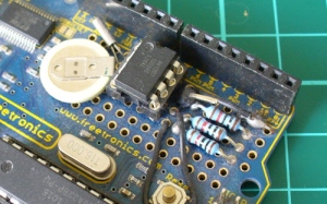
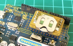
The first stage is to fit your real-time clock. If you are unfamiliar with the operation of real-time clock circuits, check out the last section of this tutorial. You can build a RTC circuit onto a protoshield or if you have a Freetronics Eleven, it can all fit in the prototyping space as such:

If you have an RTC module, it will also fit in the same space, then you simply run some wires to the 5V, GND, A4 (for SDA) and A5 (for SCL):

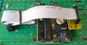
By now I hope you’re thinking “how do you set the time?”. There’s two answers to that question. If you’re using the DS3232 just set it in the sketch (see below) as the accuracy is very good, you only need to upload the sketch with the new time twice a year to cover daylight savings (unless you live in Queensland). Otherwise add a simple user-interface – a couple of buttons could do it, just as we did with Clock Two. Finally you just need to put the hardware on the back of the DMD. There’s plenty of scope to meet your own needs, a simple solution might be to align the control board so you can access the USB socket with ease – and then stick it down with some Sugru:

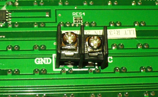
With regards to powering the clock – you can run ONE DMD from the Arduino, and it runs at a good brightness for indoor use. If you want the DMD to run at full, retina-burning brightness you need to use a separate 5 V 4 A power supply. If you’re using two DMDs – that goes to 8 A, and so on. Simply connect the external power to one DMD’s terminals (connect the second or more DMDs to these terminals):

The Arduino Sketch

You can download the sketch from here. Please use IDE v1.0.1 . The sketch has the usual functions to set and retrieve the time from DS1307/3232 real-time clock ICs, and as usual with all our clocks you can enter the time information into the variables in void setup(), then uncomment setDateDs1307(), upload the sketch, re-comment setDateDs1307, then upload the sketch once more. Repeat that process to re-set the time if you didn’t add any hardware-based user interface.

Once the time is retrieved in void loop(), it is passed to the function createTextTime(). This function creates the text string to display by starting with “It’s “, and then determines which words to follow depending on the current time. Finally the function drawText() converts the string holding the text to display into a character variable which can be passed to the DMD.

And here it is in action:

Conclusion

This was a quick project, however I hope you found it either entertaining or useful – and another random type of clock that’s easy to reproduce or modify yourself. We’re already working on another one which is completely different, so stay tuned.

In the meanwhile have fun and keep checking into tronixstuff.com. Why not follow things on twitterGoogle+, subscribe  for email updates or RSS using the links on the right-hand column? And join our friendly Google Group – dedicated to the projects and related items on this website. Sign up – it’s free, helpful to each other –  and we can all learn something.

The post Project: Clock Four – Scrolling text clock appeared first on tronixstuff.