Posts with «product review» label

Review – Freetronics 128×128 Pixel Colour OLED Module

Introduction

Time for another review, and in this instalment we have the new 128×128 Pixel OLED Module from Freetronics. It’s been a while since we’ve had a full-colour graphic display to experiment with, and this one doesn’t disappoint. Unlike other displays such as LCD, this one uses OLED – “Organic Light-Emitting Diode” technology.

OLEDs allow for a faster refresh rate, and to the naked eye has a great amount of colour contrast. Furthermore the viewing angles are excellent, you can clearly read the display from almost any angle, for example:

However they can suffer from burn-in from extended display of the same thing so that does need to be taken into account. Nevertheless they provide an inexpensive and easy-to-use method of displaying colour text, graphics and even video from a variety of development boards. Finally – there is also a microSD socket for data logging, image storage or other uses. However back to the review unit. It arrives in typical retail packaging:

and includes the OLED display itself, a nifty reusable parts tray/storage box, and two buttons. The display has a resolution of 128 x 128 pixels and has a square display area with a diagonal size of 38.1 mm. The unit itself is quite compact:

The display is easily mounted using the holes on the left and right-hand side of the display. The designers have also allowed space for an LED, current-limiting resistor and button on each side, for user input or gaming – perfect for the  included buttons. However this section of the PCB is also scored-off so you can remove them if required. Using the OLED isn’t difficult, and tutorials have been provided for both Arduino and Raspberry Pi users.

Using with Arduino

After installing the Arduino library, it’s a simple matter of running some jumper wires from the Arduino or compatible board to the display – explained in detail with the “Quickstart” guide. Normally I would would explain how to use the display myself, however in this instance a full guide has been published which explains how to display text of various colours, graphics, displaying images stored on a microSD card and more. Finally there’s some interesting demonstration sketches included with the library. For example, displaying large amounts of text:

… the variety of fonts available:

… and for those interested in monitoring changing data types, a very neat ECG-style of sketch:

… and the mandatory rotating cube from a Freetronics forum member:

Using with Raspberry Pi

For users of this popular single-board computer, there’s a great tutorial and some example videos available on the Freetronics website for your consideration, such as the following video clip playback:

Support

Along with the Arduino and Raspberry Pi tutorials, there’s also the Freetronics support forum where members have been experimenting with accelerated drivers, demonstrations and more.

Competition!

For a chance to win your own OLED display, send a postcard with your email address clearly printed on the back to:

OLED Competition, PO Box 5435 Clayton 3168 Australia. 

Cards must be received by 24/10/2013. One card will then be selected at random and the winner will be sent one Freetronics OLED Display. Prize will be delivered by Australia Post standard air mail. We’re not responsible for customs or import duties, VAT, GST, import duty, postage delays, non-delivery or whatever walls your country puts up against receiving inbound mail.

Conclusion

Compared to previous colour LCD units used in the past, OLED technology is a great improvement – and demonstrated very well with this unit. Furthermore you get the whole package – anyone call sell you a display, however Freetronics also have the support, tutorials, drivers and backup missing from other retailers. So if you need a colour display, check it out.

And for more detail, full-sized images from this article can be found on flickr. And if you’re interested in learning more about Arduino, or want to introduce someone else to the interesting world of Arduino – check out my book (now in a third printing!) “Arduino Workshop” from No Starch Press.

In the meanwhile have fun and keep checking into tronixstuff.com. Why not follow things on twitterGoogle+, subscribe  for email updates or RSS using the links on the right-hand column? And join our friendly Google Group – dedicated to the projects and related items on this website. Sign up – it’s free, helpful to each other –  and we can all learn something.

[Note – OLED display was a promotional consideration from Freetronics]

The post Review – Freetronics 128×128 Pixel Colour OLED Module appeared first on tronixstuff.

Exploring the TI Stellaris platform with Energia Arduino-compatible IDE

Introduction

In the same manner as their MSP430 development board, Texas Instruments also have another LaunchPad board with their powerful Stellaris LM4F120H5QR microcontroller. It’s an incredibly powerful and well-featured MCU – which offers an 80 MHz, 32-bit ARM Cortex-M4 CPU with floating point, 256 Kbytes of 100,000 write-erase cycle FLASH and many peripherals such as 1MSPS ADCs, eight UARTs, four SPIs, four I2Cs, USB & up to 27 timers, some configurable up to 64-bits.

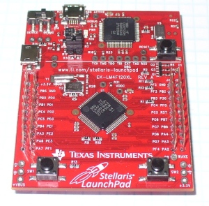
That’s a bucket of power, memory and I/O for not much money – you can get the LaunchPad board for around $15. This LaunchPad has the in-circuit debugger, two user buttons, an RGB LED and connectors for I/O and shield-like booster packs:

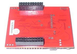
and the other side:

However the good news as far as we’re concerned is that you can now use it with the Energia Arduino-compatible IDE that we examined previously. Before rushing out to order your own Stellaris board, install Energia and examine the available functions and libraries to make sure you can run what you need. And if so, you’re set for some cheap Arduino power.

Installation

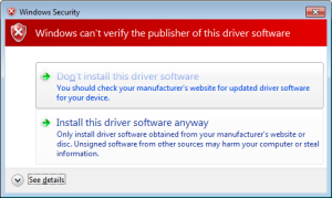
Installation is simple, just get your download from here. If you’re running Windows 7 – get the USB drivers from here. When you plug your LaunchPad into the USB for the first time, wait until after Windows attempts to install the drivers, then install drivers manually after download via Device manager … three times (JTAG, virtual serial port and DFU device). Use the debug USB socket (and set the switch to debug) when installing and uploading code. If you get the following warning from Windows, just click “Install this driver software anyway”:

Once the drivers are installed, plug in your LaunchPad, wait a moment – then run Energia. You can then select your board type and serial port just like the Arduino IDE. Then go ahead and upload the “blink” example…

Awesome – check out all that free memory space. In the same manner as the MSP430, there are some hardware<>sketch differences you need to be aware of. For example, how to refer to the I/O pins in Energia? A map has been provided for front:

… and back:

As you can imagine, the Stellaris MCUs are different to an AVR, so a lot of hardware-specific code doesn’t port over from the world of Arduino. One of the first things to remember is that the Stellaris is a 3.3V device. Code may or may not be interchangeable, so a little research will be needed to match up the I/O pins and rewrite the sketch accordingly. For example, instead of digital pins numbers, you use PX_Y – see the map above. So let’s say you want to run through the RGB LED… consider the following sketch:

int wait = 500;
void setup() 
{ 
 // initialize the digital pin as an output.
 pinMode(PF_1, OUTPUT); // red 
 pinMode(PF_3, OUTPUT); // green
 pinMode(PF_2, OUTPUT); // blue
}
void loop() 
{
 digitalWrite(PF_1, HIGH); 
 delay(wait); 
 digitalWrite(PF_1, LOW); 
 digitalWrite(PF_3, HIGH); 
 delay(wait); 
 digitalWrite(PF_3, LOW); 
 digitalWrite(PF_2, HIGH); 
 delay(wait); 
 digitalWrite(PF_2, LOW); 
}

Which simply blinks the red, green and blue LED elements in series. Using digital inputs is in the same vein, and again the buttons are wired so when pressed they go LOW. An example of this in the following sketch:

void setup() 
{ 
 // initialize the digital pins
 pinMode(PF_1, OUTPUT); // red 
 pinMode(PF_3, OUTPUT); // green
 pinMode(PF_2, OUTPUT); // blue

 pinMode(PF_4, INPUT_PULLUP); // left - note _PULLUP
 pinMode(PF_0, INPUT_PULLUP); // right - note _PULLUP 
}
void blinkfast() 
{
 for (int i=0; i<10; i++)
 {
 digitalWrite(PF_1, HIGH); 
 delay(250); 
 digitalWrite(PF_1, LOW); 
 digitalWrite(PF_3, HIGH); 
 delay(250); 
 digitalWrite(PF_3, LOW); 
 digitalWrite(PF_2, HIGH); 
 delay(250); 
 digitalWrite(PF_2, LOW); 
 }
}
void blinkslow() 
{
 for (int i=0; i<5; i++)
 {
 digitalWrite(PF_1, HIGH); 
 delay(1000); 
 digitalWrite(PF_1, LOW); 
 digitalWrite(PF_3, HIGH); 
 delay(1000); 
 digitalWrite(PF_3, LOW); 
 digitalWrite(PF_2, HIGH); 
 delay(1000); 
 digitalWrite(PF_2, LOW); 
 }
}
void loop()
{
 if (digitalRead(PF_4)==LOW) { blinkslow(); }
 if (digitalRead(PF_0)==LOW) { blinkfast(); }
}

And for the non-believers:

Where to from here? 

Sometimes you can be platform agnostic, and just pick something that does what you want with the minimum of time and budget. Or to put it another way, if you need a fast CPU and plenty of space but couldn’t be bothered don’t have time to work with Keil, Code Composer Studio, IAR etc – the Energia/Stellaris combination could solve your problem. There’s a growing Energia/Stellaris forum, and libraries can be found here. At the time of writing we found an I2C library as well.

However to take full advantage of the board, consider going back to the TI tools and move forward with them. You can go further with the tutorials and CCS etc from Texas Instruments own pages.

In the meanwhile have fun and keep checking into tronixstuff.com. Why not follow things on twitterGoogle+, subscribe  for email updates or RSS using the links on the right-hand column? And join our friendly Google Group – dedicated to the projects and related items on this website. Sign up – it’s free, helpful to each other –  and we can all learn something.

The post Exploring the TI Stellaris platform with Energia Arduino-compatible IDE appeared first on tronixstuff.